
After a software system has been designed, implemented, and validated, it is ready for operation. That usually requires that the system's components and connectors first be distributed to the "target" hardware processors. A software system cannot fulfill its purpose until it is deployed, that is, until its executable modules are physically placed on the hardware devices on which they are supposed to run. The outcome of the activity of placing a system's software components on its hardware hosts is the deployment of the system's architecture.
Once the system is in operation, it is possible, and often necessary, to change the physical location of its hardware hosts. For example, laptop computers, personal digital assistants (PDAs), cellular telephones, software-controlled radios, and computers embedded in a vehicle, all move regularly while staying connected. More challenging, more interesting to a software engineer (and even a user), and more pertinent to this book is the relocation or migration of a software component or connector from one hardware host to another. This may need to be done to improve the system's performance, perhaps by collocating a processing component with the data it needs, lessen the computational load on a given host, or to achieve some other property. Relocating software modules in this manner changes the deployment view of the software system's architecture during the system's run time, and is referred to as migration or redeployment. Run time system migration (or redeployment) is thus a type of a software system's mobility.
It should be noted that changing a system's deployment while it is running in many ways entails a superset of concerns that engineers face during initial deployment, including the following.
During a component's migration, its run time state may need to be preserved and migrated. On the other hand, during initial deployment, prior to system start-up, components are typically stateless.
Systems experience temporary downtimes, or at least degradations in provided capabilities and performance, during the migration process. These concerns do not affect the system during its initial deployment.
The time at which a component is migrated during execution must be chosen very carefully, as the component must not be in the middle of computation or interaction with another component. Again, these concerns are not applicable during the system's initial deployment.
The added complexity of run time redeployment, indicated in the above points, is coupled with the usually significantly reduced amount of time available to ensure that all critical system properties have been preserved. In contrast, engineers can carefully plan and analyze a system's initial deployment over a comparatively much longer period of time.
Fundamentally, the role of hardware in the context of deployment and mobility is to support a system's software architecture, including the functionality embodied in processing components, the information exchanged via data components, the interactions facilitated by connectors, and the overall structure defined by the configuration. The hardware configuration can, in turn, also present constraints that must be supported by the software architecture: The choice of distribution points will induce certain architectural decisions. The deployment view of a software system's architecture can be critical in assessing whether the system will be able to satisfy its requirements. For example, placing many large components on a small device with limited memory and CPU power, or transferring high volumes of data over a network link with low bandwidth will negatively impact the system, much like incorrectly implementing its functionality will.
To illustrate these issues, consider the configuration of hardware devices shown in Figure 10-1. This configuration is typical of those used in wireless sensor network systems those found in many commercial buildings, power plants, and transportation systems. The sensor devices host software that can help determine the conditions of their outside environment, such as motion, vibration, fire, and moisture. Sensors are typically highly resource-constrained and can only perform minimal amounts of computation and data storage. The gateway devices aggregate, process, and can possibly share this information. They pass it on to the hubs, which may run software that can make appropriate decisions in the case of certain events or changes in system status. For example, if a gateway fails, a hub may instruct another gateway to take over the management of the "orphaned" sensors; likewise, if multiple sensors report events of a given type (such as excess moisture), the hub may decide that it is appropriate to sound an alarm. Both the gateways and hubs have significantly higher capacities than the sensors, and may be able to perform large amounts of computation and/or store large amounts of data. Finally, humans can observe the system's operation via PDAs, which communicate with the hubs. PDAs are usually more capacious than sensors, but not as capacious as the hubs or the gateways. The four types of devices may all run different operating systems and other system-level software, require different dialects of programming languages, and support different network protocols.

Figure 10-1. A wireless sensor network system comprising hardware devices of several types, on which a software system is deployed.
Software engineers must take into account information such as the above when deciding how to deploy the software system onto the requisite hardware hosts. Furthermore, this information will directly impact the options an engineer has for redeploying the system's components—and possibly connectors—during run time. The idiosyncrasies of a given platform will thus serve as software deployment and mobility constraints.
In addition to considering the characteristics of the involved hardware devices, certain application-level requirements may have a significant impact on the given software architecture's deployment and mobility. For example, the maximum allowed round-trip time between the reporting of an event by a sensor and the acknowledgment that the event has been received by an upstream processing component may affect where certain processing and data components are placed in the system, such as on the gateway or the hub. Such a requirement may also impact the flow of information, for instance whether and when human users need to be informed versus when the software system itself can make a decision.
As another illustrative example, consider an emergency response system (ERS), whose screenshot is shown in Figure 10-2. The devices in this system are somewhat more homogeneous than in the previous example: There is a small number of powerful laptop computers, which are overseeing the overall operation. The laptops interact primarily with a set of high-end PDAs that are in charge of specific segments of the operation; in turn, each of these PDAs interacts with a large number of lower-end PDAs, which are used by individuals who participate as first-line responders. Even though they run different operating systems, each device type is capable of displaying a user interface, running Java, and communicating via TCP/IP. Therefore, aside from the computational and storage capabilities of the different devices, the number of constraints that need to be considered during a software system's deployment, and redeployment, is smaller than in the case of the wireless sensor network system from Figure 10-1.
In this chapter, we study the impact of an explicit software architectural focus on system deployment and mobility. Conversely, we will also study the impact of deployment and mobility on software architecture. The reader should note that deployment can be viewed as a special case of mobility, that is, as the mobility of software modules prior to the system's run time. The two concepts are thus closely related and many of their resulting challenges, ramifications, techniques, and tools are similar.

Figure 10-2. An instance of the family of emergency response systems (ERS), which help with deploying and organizing teams of humans in cases of natural disasters, search-and-rescue operations, and military crises (© IEEE 2005).
The objective of this chapter is to define and, where necessary, clarify the role of software architecture in deployment and mobility, to discuss different approaches to software deployment and mobility, and to present a set of deployment and mobility techniques that are at an engineer's disposal. We illustrate the main points in the discussion via examples from existing solutions. While software deployment and mobility are two important and growing areas of study, our focus here is specifically on their architecturally relevant aspects. An annotated list of references will be given at the end of the chapter for a broader treatment of the two areas.
Outline of Chapter 10
10 Deployment and Mobility
10.1 Overview of Deployment and Mobility Challenges
10.2 Software Architecture and Deployment
10.2.1 Basic Concepts
10.2.2 Deployment Activities
10.2.3 Tool Support
10.3 Software Architecture and Mobility
10.3.1 Basic Concepts
10.3.2 Mobility Paradigms
10.3.3 Challenges in Migrating Code
10.4 End Matter
10.5 Review Questions
10.6 Exercises
10.7 Further Reading
Modern software systems can present a number of deployment and mobility challenges. Several of these are outlined below.
The target processors may be geographically widely distributed, sometimes even throughout the solar system, as is the case with some of NASA's space missions. Physically deploying the software in such settings presents logistical problems, especially if the software has to be distributed and deployed during the system's execution. For example, it may take minutes, and even hours, for the software to reach the intended target host. An accompanying concern is the security of such systems, especially during the transfer of code.
The target processors may be embedded inside heterogeneous devices that have different operating environments and serve different purposes. For example, aircraft, mobile robots, consumer electronic devices, mobile phones, and desktop computers present very different characteristics. A software component running on one device may not be able to run on another. Therefore, transferring a component from one such device to another may require use of sophisticated adaptor software connectors (recall Chapter 5), thus potentially affecting the system's overall performance. Such redeployments may often be impossible.
Different software components may require different hardware configurations for their successful execution, whether screen resolution, CPU speed, I/O devices, or memory. Again, this requires careful planning and analysis of the intended deployment profiles or run time software migrations.
Typical system life spans may stretch over decades and require periodic maintenance, meaning usually that parts of the system may need to be redeployed. For example, a "buggy" component may be replaced or a more reliable connector introduced. This means that redeployment is an unavoidable activity in most software systems. It also means that, as existing components exhibit problematic behaviors, engineers may resort to migrating software to improve system performance.
Similarly, the deployed system is likely to evolve over time, again requiring redeployment. New functionality may be introduced and individual components or even entire hosts may be replaced with newer versions. The danger in this, as well as in the previous case, is that the deployed system's architecture will degrade.
The emerging class of mobile code solutions, such as mobile agents (Fuggetta, Picco, and Vigna 1998), require that running components be redeployed from one host to another. This requires carefully assessing acceptable (partial) system downtimes and employing techniques for capturing and transferring the relevant portion of the system's dynamic state in addition to the code.
After a component has been relocated, it still must be able to discover and access, from its new location, the system services it needs at run time. Likewise, the rest of the system needs to be able to locate and access the services provided by that component. Selecting existing or developing new mechanisms for ensuring continuous access to system services is a major architectural consideration in mobile systems.
Traditionally the problem of mobility, and especially initial system deployment, is handled in a relatively uniform manner, and it does not always reflect the above scenarios. For example, if a Windows PC user wants to upgrade an operating system or application on his or her PC, or install a patch that will remove an existing problem, he either will obtain a CD-ROM with the needed software or go to a Web site and download the software; the user will then have to shut down all applications running on the PC in order to complete the procedure. While the PC user is controlling the deployment process, this human user- in-the-loop approach relies on certain assumptions, such as the fact that a computer's operating environment is one of a small handful of tightly controlled environments supported by the provider of new functionality. Regardless of a PC user's technical prowess, the user usually will have little insight into the changes done to the code running on the PC. In other words, the precondition for, say, installing a new spell-check component into a word processor is that its user place full trust in the component's developer, hope that the new software will work correctly, that it will eliminate any problems the user may have had with the previous spell-checker, and that it will not introduce any new bugs. As we all know from experience, sometimes these patches fix the problems, and sometimes they do not, but eventually most PC users reach the point where the performance of the computer has degraded so badly that the only true remedy is to "reinstall the PC" completely. [12]
The situation is even more extreme if a commodity device, such as an automobile, cellular telephone, or "smart" cable TV box, begins misbehaving. In such cases, chances are that the owner or user will have to rely on a trained professional for a remedy. That will often require relinquishing control of the device for a period of time, during which all software running on the device will be redeployed and reinstalled from scratch or simply will be replaced along with the processor on which it is running. In the process, any questions the owner or user may have about what is actually going on with the device will almost assuredly be given euphemistic nonanswers because even the trained professionals do not understand the underlying causes, other than the fact that over time something in the software went awry.
Whatever that "something" is, it probably has underlying architectural causes. Every time a new software system is deployed on its target hosts, its initial deployment architecture is established. When that initial system is changed—via a security patch, by deploying a new component, or by adding a new host—its architecture also changes. If the architectural implications of those changes are not carefully analyzed and clearly understood, the system's architecture is bound to degrade. Eventually, the architecture degrades to the point where the system is unable to function properly, requiring a complete overhaul, as in the above scenarios.
Even though the two are related, the remainder of the chapter addresses separately the role of software architecture in the deployment and in the mobility of software systems.
Deployment is the set of activities that result in placing a given software system's components and connectors on a set of physical hosts. This set of activities can take place both during the system's construction, that is, prior to run time, as well as during its execution. In the latter case, deployment entails the transfer and activation of components/connectors that are added to the system for the first time—in other words, either new elements or new versions of existing elements. If the elements deployed on a given host had previously been running on another host in the system, thus possibly having run time state, that is considered to be a case of code mobility and is discussed in the next section.
In the rest of this section, we first introduce the basic concepts underlying software deployment. We then elaborate the set of key deployment activities with a specific focus on the role software architecture plays in them. Finally, we discuss the tool support required of architecture-driven software deployment.
The overview of the key concepts that underlie software deployment, provided in this section, draws from a deployment technology characterization framework by Antonio Carzaniga, Alfonso Fuggetta, Richard Hall, Dennis Heimbigner, André van der Hoek, and Alexander Wolf (Carzaniga et al. 1998).
A software system is deployed on one or more hardware devices, referred to as hosts or sites. Each site provides a set of resources needed for hosting and executing the system or some of its subsystems. The resources include the different elements of the following.
The hardware architecture (such as memory and CPU).
The network architecture (such as available protocols and IP port numbers).
The peripheral devices (such as hard disk and keyboard).
The system software (such as operating system, device drivers, and middleware).
Other application-level software (such as GUI builders and databases).
The data resources (such as data files and Globally Unique Component Identifiers or GUIDs).
Resources can be either exclusive (such as IP port number, GUID) or sharable (such as CPU, data file).
A software system is composed from a specific set of components and connectors, with carefully prescribed interconnections and allowed interactions. Multiple versions of the components and connectors may exist, meaning that the system itself may have multiple versions as well. A version is defined to be a time-ordered revision, a platform-specific variant, or a functional variant.
Initial system deployment involves the transfer of system components or connectors from one or more source or producer hosts to one or more destination or consumer hosts. Subsequent deployment activity will typically involve introducing new functionality (that is, new components) to the system, or replacing existing components or connectors with different versions.
Architecture-driven software deployment comprises a process that must be carefully planned, modeled, analyzed, and finally effected or executed. We discuss these four activities in more detail below, and specifically focus on the relationship between each activity and software architecture.
It is critical that the deployment of a software system be carefully planned. Many important system properties, particularly in a distributed setting, will be affected by the system's deployment. For example, the system's latency in delivering a given service can be improved if the system is deployed such that the most frequent and voluminous interactions required for that service occur either locally or over reliable and capacious network links.
For any large, distributed system, many deployments—that is, mappings of software components and connectors onto hardware hosts—will be possible in principle. Some of those deployments will be more effective than others in ensuring the desired system properties, such as its dependability, availability, security, and fault-tolerance. A system that meets its requirements and possesses these properties is said to deliver a desired level of service quality, most often referred to as QoS for "quality of service," to its users. Of course, in order to be able to claim that the system delivers the required QoS, the different QoS dimensions must be measurable and quantifiable. We revisit this issue in the next section. In the remainder of this section, we assume that the QoS dimensions in question are, in fact, measurable and quantifiable.
It should be noted that there are cases in which the deployment decisions can be and are made with relative ease—regardless of whether they are actually a good fit for the given system or not. One example is a typical desktop environment, in which a human user decides the software that he wants installed on his personal computer. Another example would be a system deployed by a space agency, comprising an interplanetary probe and a ground station. In such systems, it is typically known a priori on which side (flight or ground) the system's different components will reside. Yet another example, to an extent, is the wireless sensor network system depicted in Figure 10-1: The GUI components implemented in Java will reside on the PDAs, while the computationally intensive components implemented in C++ will be deployed to either the hubs or gateways (Malek et al. 2007). While the potential presence of multiple hubs and gateways, and multiple types of PDAs, still will require that the system's architects and engineers consider the effects of their deployment decisions within each class of components (in this example, GUI components and computationally intensive components, respectively), the number of possible deployments is significantly reduced.
The deployment problem is substantially more challenging in a system such as the one depicted in Figure 10-2, in which the number of hardware hosts is significantly larger and all devices provide roughly similar execution environments (in this case, Java). The problem of determining an effective deployment becomes intractable for a human engineer if, in addition to this, multiple QoS dimensions such as latency, security, availability, and power usage must be considered simultaneously, while taking into account any additional constraints. For example, component X may not be deployed on hosts Y and Z because of the component's size, the hosts' inability to provide the resources necessary for its execution, security concerns, or something else. This is a particularly challenging problem because of the following issues.
A very large number of system parameters influence the QoS dimensions of a software system. It may be possible to identify a subset of system parameters, such as network bandwidth, network reliability, and frequencies of component interactions, that influence the majority of QoS dimensions; however, it may not be possible to identify all of them.
Many services provided by a system and their corresponding QoS influence the system users' satisfaction.
Different service qualities may be conflicting; that is, improving one may degrade another. A simple example is security and efficiency: If the system's designers elect to use powerful encryption facilities for all network traffic, such a decision will very likely have a direct, negative impact on the system's performance.
The space of possible deployment architectures for a given software system is exponentially large.

Figure 10-3. A small subset of the ERS system's architecture, comprising two software components and two hardware hosts. The components are depicted in UML for convenience.
In general, for a system comprising c software components and connectors that need to be deployed onto h hardware hosts, there are h c possible deployments. Clearly, some of those deployments may not be valid due to location constraints such as those mentioned above, memory restrictions on different devices, network bandwidth considerations, or availability of hardware and system software. This will reduce the space of possible deployments. On the other hand, the human user still must determine which deployment he prefers, why, and, in the process, may have to consider multiple invalid deployments.
As a simple example, consider the following scenario. A very small subset of the ERS system's architecture sketched in Figure 10-2 is depicted in Figure 10-3. This particular system contains only two software components and two hardware hosts; the connector enabling the interaction between the two components has been elided for simplicity. The two components interact to provide a schedule resource service, and the only property (that is, QoS dimension) of interest is latency. This small system has four possible deployments:
Both components are deployed on the PDA.
Both components are deployed on the laptop.
ModifyResourceMapis deployed on the PDA, whileResourceMonitoris deployed on the laptop.ResourceMonitoris deployed on the PDA, whileModifyResourceMapis deployed on the laptop.
For such a small system, it is, in fact, possible to consider all of the possible deployments and to measure their actual latency. Let us assume that the measured latencies of the four deployments are as shown in Figure 10-4(a). These values are hypothetical, used here for illustration only. From this data, it is easy to determine that the first deployment exhibited the shortest latency and is thus the optimal deployment.
Let us now extend the example slightly and introduce another QoS dimension—durability. We define durability as the inverse of the system's rate of energy consumption. In many embedded and mobile settings, systems with higher energy consumption rates will run out of battery power sooner, that is, they will have lower durability. Therefore, deployments that reduce the energy consumption rate will increase the system's durability.
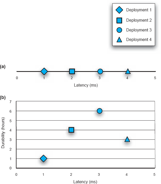
Figure 10-4. Evaluating deployments of the ERS subsystem from Figure 10-3. (a) Latency is the only QoS dimension of interest. (b) Latency and durability are the two QoS dimensions of interest.
Figure 10-4(b) shows the (hypothetical) durability values plotted alongside the previously obtained latency values. The first deployment still exhibits the shortest latency, but the third deployment is most durable. This phenomenon is known as Pareto optimal in multicriteria problems such as this one: No single deployment can be considered optimal unless additional criteria are introduced that will allow an architect to reconcile the two competing deployment options. In this example, if the system's stakeholders deemed durability more important than latency, the third deployment would likely be selected over the first one. However, even if there is no such additional criterion, the architect still has all relevant data available and can make the decision(s) he deems most appropriate.
To illustrate how quickly this problem becomes intractable, let us consider a slightly expanded scenario, depicted in Figure 10-5: This subsystem of the ERS has three components and three hosts. Even though it does not directly impact the discussion below, for the sake of completeness it should be noted that this three-component system provides an exchange plan service as well as the schedule resource service. Furthermore, there are now three QoS dimensions of interest: In addition to minimizing latency and maximizing durability, the system must also minimize the total volume of data exchanged across the network.

Figure 10-5. A slightly larger subset of the ERS system's architecture, comprising three software components and three hardware hosts.
This system has twenty-seven possible deployments (33). For each of those deployments, let us assume that the three QoS properties have been measured or estimated. Visualizing the twenty-seven data points in a single three-dimensional diagram would be possible, though difficult. Note that visualizing software deployment scenarios with greater numbers of components and hosts, and especially with four or more QoS dimensions, in a single diagram would be essentially impossible. Instead, architects would most likely plot separate two-dimensional diagrams to study the relationships between pairs of QoS dimensions. The three such diagrams for the scenario from Figure 10-5 are shown for illustration in Figure 10-6.
It should be obvious from this example that, even for a system that is as small as the one depicted in Figure 10-5, manually calculating the QoS values of individual deployments and then determining the best deployment from those values is infeasible. Therefore, a solution that meets the challenges identified above and allows a software system's architects to plan the system's deployment appropriately will need to (1) provide an extensible model that supports inclusion of arbitrary system parameters; (2) support the definition of new QoS dimensions using the system parameters; (3) allow users to specify their QoS preferences; and (4) provide efficient and generic algorithms that can be used to find a solution (that is, deployment architecture) which maximizes the users' satisfaction in a reasonable amount of time.

Figure 10-6. The pair–wise trade-offs among the three QoS of interest (latency, durability, and interaction volume) for the ERS subsystem shown in Figure 10-5.
This solution is amenable to implementation, alleviating at least some of the architect's responsibility. In turn, this allows architects to focus on tasks such as specifying concrete targets for QoS dimensions of interest, rather than on menial but critical tasks such as determining whether a given deployment satisfies all of the system constraints and, if so, calculating the values of its various QoS dimensions.
For example, in the case of the scenario from Figure 10-5 and Figure 10-6, the architect may be interested in a deployment with specific latency, durability, and interaction volume thresholds. Manually determining and analyzing each individual deployment that is possible, that is, that satisfies all system constraints, and choosing one that in fact meets the set thresholds, would be overly time consuming (it could take hours for this small scenario and years for even only slightly larger systems) and error-prone. Furthermore, the architect will likely elect to stop once he has found the first deployment that meets the desired criteria. In contrast, a software-based solution working on the same problem would likely be able to determine a number of valid deployments that meet the QoS criteria, and choose the best one.
Automated support for deployment modeling and analysis would also allow architects to study, and quantify, any changes in a system's run time behavior. In turn, this would allow them to formulate plans regarding whether and when to redeploy the system or some of its parts.
In order to be able to make and effect a deployment plan for a large, long-lived, distributed software system, the system's architects first need to create a detailed model comprising all concerns pertaining to the system's deployment. This is an example of several concerns pertaining to the system's hardware and network infrastructure permeating the space of principal design decisions, that is, the system's software architecture.
Consider the two diagrams in Figure 10-7, corresponding to a subset of the ERS application depicted in Figure 10-2: The top diagram shows a high-level view of the ERS system's architectural configuration, while the bottom diagram shows the configuration of the hardware hosts on which the software is to be deployed. For simplicity, the top diagram does not show any software connectors. Instead, all interaction paths among the components are represented simply as lines. The reader can choose to interpret them as procedure calls for the purpose of the ensuing discussion. The dashed lines in the bottom diagram depict network connectivity.
A software architect would need a lot more information than is contained in the two diagrams in Figure 10-7 to determine what an effective deployment of ERS's software components to its hardware hosts would be. For example, the architect would need to know how computationally intensive the Deployment Advisor component is; how large the Repository is; how frequently the Clock component updates the remaining components in the system; what type of GUI facilities the five UI components in the system require; and so on. Furthermore, the architect would need to know many of the characteristics of the five hosts (such as their capacities, available peripheral devices, system-level software running on each, and so on) as well as the network links connecting them (such as the available bandwidth, protocol, link reliability, and so on). Only after all of this information is available can the architect make appropriate deployment decisions.
Therefore, an effective deployment model requires the following elements:
Software system elements (components and connectors), their configuration, and their parameters.
Hardware system elements (hardware hosts and network links), their configuration, and their parameters.
Any constraints on the system elements and/or their parameters.
Formal definitions of QoS dimensions of interest.
The architects may also need to represent system users or user types and their preferences in order to make appropriate decisions in situations in which multiple deployment options are acceptable.
For any moderately-sized software system, the above model can be very large, especially if architects decide to capture many parameters and constraints of the overall system and its individual hardware and software elements. Example parameters of a software component are the CPU and memory requirements for the component's execution, characteristics of the required execution substrate, such as the needed version of the Java Virtual Machine, and so on. Likewise, for a connector enabling the interaction of two or more components, the system model would encompass many of the same parameters as in the case of components, but would also capture parameters such as the sizes and frequencies of the interaction between the components, security mechanisms available, and whether the connector assumes a particular distribution profile (such as single address space, interprocess, or network-based).

Figure 10-7. The software architectural configuration of a subset of the ERS application (top) and the hardware configuration on which the software is to be deployed (bottom).
Even though the primary responsibility of a software architect is to focus on a system's software aspects, in the case of deployment modeling software architects must also consider the characteristics of the hardware platforms and the network. Extensible architecture descriptions languages such as xADL, AADL, and even UML, discussed in Chapter 6, are able to or already incorporate such modeling elements.
There may be many constraints specified on the software and hardware elements of a deployment model. For instance, location constraints may specify the relationship between software and hardware elements: requiring, allowing, or prohibiting that certain elements be deployed on certain hosts. In the example from Figure 10-7, it may be required that the Clock component reside on Host 2, while the Repository component may be prohibited from residing on that host.
Collocation constraints specify groups of components and connectors that need to be deployed, and redeployed, as a collection, as well as groups of components and connectors that may not be deployed on the same host. For example, another way of specifying the above two location constraints for Figure 10-7 would be to couple the Clock component's location constraint (that it must reside on Host 2) with a collocation constraint stating that the Clock and Repository components may not reside on the same host.
Beyond location and collocation, other constraints may restrict the versions of software connectors that may be used to enable the interactions of specific versions of components, the hardware configurations that are required or disallowed for deploying a given component, and so on. A final, critical facet of a deployment model is a quantification of the QoS dimensions of interest. If a given system property cannot be quantified, it cannot be estimated or measured precisely and the impact on that property of a system's particular deployment cannot be assessed objectively. Thus, for example, trying to determine a deployment of the ERS that will optimize its usability would be inherently difficult: Usability is a largely subjective notion that depends on many, sometimes implicit and possibly ill-understood, factors.
Fortunately, many important system properties can be quantified: reliability, availability, size, energy consumption rate, latency, and data volume are examples. Some of these properties may have multiple interpretations, which will differ across architects, projects, and organizations. Nonetheless, in principle it is possible to select a specific definition for a given property. Thus for example, one possible definition of availability for a system service (such as schedule resource discussed in the context of Figure 10-3) may be as the ratio of the successfully completed service requests to the total number of attempted service requests. It is not critical that this be the only, or the best, definition of availability. It is much more important that the definition fits the needs of the project in question, and that it is applied consistently.
Developing a detailed deployment model will be a sizeable, human-intensive task for any large, distributed application: Many parameters of many system elements will have to be modeled; many constraints will have to be captured; QoS dimensions of interest will have to be formally defined; system users and their preferences will have to be modeled; and so on. Doing all that will be worthwhile only if the model is used effectively to make the necessary, complex deployment decisions. To that end, the system's deployment model will have to be analyzed for properties of interest.

Consider for illustration the two diagrams in Figure 10-8. Both represent deployments of the ERS application's software elements onto its hardware nodes. The connectivities of both the software and the hardware configurations in the two Figure 10-8 diagrams are identical to those depicted in Figure 10-7. In other words, the applications corresponding to the two deployments are functionally equivalent to each other. The only difference between the two diagrams is that some of the software elements have been repositioned across the hosts. Using the terminology introduced in Chapter 3, we can then say that the two diagrams represent different candidate deployment views of the ERS application's architecture. An architect considering these two candidate deployments will have to make certain determinations, as detailed below.
First, are both deployments valid? That is, do they satisfy all ERS system constraints?
Secondly, which of the two deployments is better?
Finally, once the better deployment is selected, does that deployment exhibit acceptable properties, or must an even better deployment be found?
Answering the first question—Is a deployment valid?—is relatively easy. If the system constraints have been specified rigorously, then this becomes a straightforward constraint satisfaction problem.
The answer to the second question—Which deployment is better?—is more uncertain. To answer that question, the architect must have a clearly defined measure of goodness for a system's deployment. That means that the system's deployment model will need to provide definitions of all QoS dimensions of interest. In turn, these QoS dimensions will have to be measured, or at least estimated. If multiple QoS dimensions are under consideration, as will be the case with most all large systems, the architect will very likely have to deal with Pareto optimal situations (recall from Figure 10-4(b): One deployment may prove superior with respect to one subset of the QoS dimensions, while another deployment may be better with respect to a different subset of the QoS dimensions.
For this reason, additional criteria will have to be introduced into the model. One possibility is to rank the QoS dimensions. For example, it may be decided that durability is more critical than latency. In that case, the third deployment from Figure 10-4(b) would be selected.
Another possibility, as suggested previously, is to introduce system users into the deployment model and capture their preferences explicitly. For example, one user could state that high durability of the schedule resource service in the ERS system is more important, by a given quantified factor, than its low latency; another user may specify another, possibly clashing preference. This would allow the architects to introduce the notion of the system's utility and select the deployment that provides the greatest total utility to all the users, or alternatively, the deployment that provides the greatest utility to the most important user or users.
Answering the third question—Is there a better deployment than the current one?—can be very challenging. It may require considering a very large number of deployment options and for each of them establishing the deployment's validity and comparing the new deployment to the existing one. This question is closely related to a more general question—What is the best deployment possible for a given system?—which is infeasible to answer in the general case because of the deployment problem's exponential nature.
There is a class of algorithms that can be applied to questions such as these. As stated above, the deployment problem is an instance of multidimensional optimization problems. Techniques such as mixed-integer linear programming (MIP) and mixed-integer nonlinear programming (MINLP) are frequently used to solve such problems (Nemhauser and Wolsey 1988). The main shortcoming of MIP is that it searches exhaustively for the best solution to a problem, and is thus inapplicable to even moderately large deployment scenarios. MINLP algorithms in turn provide approximate, rather than optimal, solutions. Furthermore, MINLP algorithms may not always converge on a solution.
There are other heuristic-based strategies that can be applied to solving complex problems such as this, including greedy, genetic, and decentralized strategies (Malek et al. 2007). However, none of those strategies can guarantee that the suggested deployment is the optimal one. In the case of the simpler formulation of the third question—Is there a better deployment than the current one?—this may result in failing to identify a better deployment even though many such deployments may exist. In the case of the question's more general formulation—What is the best deployment possible for a given system?—this may result in selecting a deployment that is actually suboptimal but is the best deployment the chosen algorithm can find.
Once the deployment problem has been modeled and a specific software system's deployment suggested in the manner outlined above, that deployment needs to be effected. As noted by Richard Hall and colleagues (Hall et al. 1997; Hall, Heimbigner, and Wolf 1999) and Carzaniga and colleagues (Carzaniga et al. 1998), some of the activities in a software system's deployment process take place on the host that is the source of the deployed component, while other activities take place on the host that is the destination of the deployed component. Source hosts are also referred to as producers, while destination hosts are referred to as targets, or consumers. The overall relationship among these activities is shown in Figure 10-9. We will briefly discuss each of these activities below, with a particular focus on the role of software architecture in the deployment process.

Figure 10-9. Software deployment process: deployment activities and their relationships. The diagram has been adopted from (Carzaniga et al. 1998).
Release. A software system's release is the initial activity in that system's deployment process. It takes place on the producer site, or sites, after the system's development has been completed. The system is packaged so that it can be transferred to the consumer sites. In certain settings (such as desktop computing) the system may need to be advertised to potential consumers. The packaged system will typically contain the following:
The system's description, including its software architectural configuration, dependencies on system-level facilities and any external components, and requirements specific to individual software system elements and the entire system.
All of the necessary software modules—both the application and any helper components necessary for the released application's correct execution.
A deployment model indicating which components need to be deployed on which processes and/or hosts.
The deployment procedures that must be effected on the consumer sites in order to extract and deploy the software system from the release package.
Any additional information that is needed to manage the system at the consumer sites, such as the necessary periodic updates to the data used by the system and expected downtimes for specific system services.
Install. Once the system has been packaged at the producer sites and transferred to the consumer sites, it is ready to be configured and installed for operation. Installation is a complex activity that encompasses all of the steps necessary to enable the system to execute. In other words, installation deals with:
Extracting from the deployment package the system's description, including its software architecture and deployment models.
Based on those models, assembling all of the system's elements—both the application-level components as well as any accompanying utilities.
Ensuring that all the resources needed for the system's correct operation are available and properly configured.
Establishing any required conditions on the target hosts, such as setting any global system variables, establishing the needed directory structures, and setting up the appropriate classpaths.
Activate. Once the system is installed, it needs to be activated for use on the target hosts. Activation consists of providing a command, or sequence of commands, that will be required to start up the system.
Deactivate. Deactivation involves disabling and/or shutting down a system, or any of the system's facilities that are still active on the target hosts.
Update. Once a system has been installed and activated on the target hosts, over time it may need to be updated for different reasons. Updates are initiated by the system's producers, and involve the same activities as the system's original installation, with the caveat that only the necessary subset of the system is packaged and received from the producer hosts. The system may need to be deactivated before it is updated, and then reactivated thereafter. Alternatively, the system may support dynamic redeployment (recall the above discussion and also see Chapter 14). It is critical that the software system's update be properly reflected in its architectural models. If this is not ensured, the architecture will degrade, and any subsequent updates may result in system defects.
Adapt. Adaptation encompasses a wide range of activities that result in changing the system, possibly dynamically, in response to events in the system's execution environment. Adaptation is an important aspect of architecture-based software development, thus Chapter 14 is dedicated to it. With respect to software deployment, adaptation can result in the system's redeployment (that is, repositioning of its software components across execution processes and/or hardware hosts). Adaptation will be further discussed below in the context of mobility.
De-Install. If the system is no longer needed on the consumer sites, it will need to be removed. A simple view of de-installing a system is that it simply reverses the steps taken during the installation. However, any subsequent updates and adaptations must also be taken into account, as must any dependencies that other systems on the given consumer host have to the system being removed. This is why it is critical to maintain current architectural models for all deployed software systems. It should also be noted that, before the system is de-installed, it may need to be deactivated first.
De-Release. After some time, the producer of a given system may decide not to support the system any longer. In other words, the producer may decide to retire the system. This may be because one or more of the system's subsequent versions are superior, the market size for the product is too small, the producer has discontinued the product, or the producer has gone out of business. The withdrawal of the producer's support for the system is usually advertised. The system's consumers can then decide whether they still want to use the system, with the accompanying risks, or to de-install it.
To properly support the software architecture-based deployment modeling, analysis, and implementation activities discussed above, engineers must be supplied with appropriate software tools. Some of those tools, such as those for software installation, are widely used. For example, most all desktop software comes with an installation wizard. Tools for other activities are not as prevalent, and furthermore, they frequently fail to consider the system's software architecture. This carries the risk that important architectural concerns will be missed during deployment and re-deployment. It also carries the risk that key architectural design decisions will be violated. Ideally, a deployment tool set will enable architects to do the following.
Model in detail the software system's deployment concerns.
Analyze the deployment model for desired properties.
Effect or implement that deployment model.
Actively monitor the system for properties of interest.
Update or adapt the system as a result.
Tools exist that support many facets of the above activities [such as Software Dock (Hall, Heimbigner, and Wolf 1999)], but they frequently take an implementation–centric, rather than a software architecture–centric, view of the deployed system. Here we will briefly focus on a few examples of architecture-based deployment tools.
An example of an integrated tool set that allows several of these activities to take place seamlessly for the ERS application family is shown in Figure 10-10. The environment allows an architect to graphically model certain aspects of a system's deployment, including the following.

Figure 10-10. An example architecture-based software deployment environment. An application is modeled as a collection of software components and connectors, as well as hardware hosts and network links. The network link between the two bottom hosts is temporarily down (denoted by the dashed line).
Software components and connectors, as well as the locations of their implementations in Java and/or C++.
Their connectivity in the particular application's architectural configuration.
Hardware nodes and their IP addresses.
The physical network's connectivity.
Once the model of an application's deployment is completed, this tool is capable of releasing and installing the application, as well as monitoring it during run time. For example, the screenshot in Figure 10-10 shows that the network link between the two PDAs is down.

Figure 10-11. A deployment view of a software system distributed across three types of devices (top). A deployment modeling and analysis tool interacts with the system at run time to ensure the preservation of its key properties (bottom).
A more sophisticated distributed system deployment tool, called DeSi (Malek et al. 2005), is depicted in the bottom portion of Figure 10-11. DeSi allows an architect to provide a more extensive model of the system's deployment, such as that discussed earlier in this chapter. The tool also is able to analyze the model and suggest an effective deployment for a given system, which will ensure the system's key QoS dimensions. An example deployment for an application is shown in the top portion of Figure 10-11. Interested readers can refer to (Malek et al. 2007) for further details of this particular application. Finally, the tool is able to interact with the system's implementation platform, observe, and analyze any changes in the system's operating conditions. In response, DeSi reevaluates the deployment view of the system's current architecture, and may suggest and effect an improved one.
Once a software system is in operation, parts of it may need to be redeployed, or migrated, in response to changes in the run time environment or the need to improve certain non-functional properties of the system. The redeployment of a software system's components is a type of software system mobility.
Mobility is an area that has received significant attention recently. This chapter focuses specifically on those aspects of mobility that are relevant to a software system's architecture. The reader should note that, in order for software mobility to be possible, certain low-level system implementation facilities, such as dynamically linked libraries and dynamic class loading, usually must also be available. We will not focus on such facilities here as they are outside the scope of this book.
Mobile computing involves the movement of human users together with their hosts across different physical locations, while still being able to access an information system unimpeded. This is also referred to as physical mobility. Such mobile computing need not necessarily involve the mobility of software systems, or portions of them, from one host to another. If a piece of software moves across hardware hosts during the system's execution, that action is referred to as code mobility, or logical mobility.
If a software module that needs to be migrated contains run time state, then the module's migration is known as stateful mobility. If only the code needs to be migrated, that is known as stateless mobility. Clearly, supporting stateful mobility is more challenging since the mobile component's state on the source host needs to be captured, migrated, and reconstituted on the destination host. Furthermore, the component may be moved only at certain times [such as when it is not operating on its internal state; that is, when it is quiescent (Kramer and Magee 1988), as discussed in Chapter 14]. Finally, the effect of the component's migration, and thus its temporary downtime, on the rest of the system and its dependence on the component's internal state must be considered. This is why Alfonso Fuggetta, Gian Petro Picco, and Giovanni Vigna (Fuggetta, Picco, and Vigna 1998) refer to stateful mobility as strong mobility, while they consider stateless mobility to be weak mobility.
It is widely accepted that there are three general classes of mobile code systems: remote evaluation, code-on-demand, and mobile agent (Fuggetta, Picco, and Vigna 1998). These are typically distinguished from "fixed" code paradigms such as client-server. In a client-server system, the server has both the logic and the resources needed for providing a given service, while the distribution of such know-how and resources varies across the mobile code paradigms.
In remote evaluation, a component on the source host has the know-how but not the resources needed for performing a service. The component is transferred to the destination host, where it is executed using the available resources. The result of the execution is returned to the source host.
In the terminology used previously in this chapter (that is, from a software architectural perspective), this means that in remote evaluation a software component is:
Redeployed at run time from a source host to a destination host.
Installed on the destination host, ensuring that the software system's architectural configuration and any architectural constraints are preserved.
Activated.
Executed to provide the desired service.
Possibly de-activated and de-installed.
In code-on-demand, the needed resources are available locally, but the know-how is not. The local subsystem thus requests the component(s) providing the know-how from the appropriate remote host(s).
From a software architectural perspective, code-on-demand requires the same steps as remote evaluation; the only difference is that the roles of the target and destination hosts are reversed.
If a component on a given host (1) has the know-how for providing some service, (2) has some execution state, and (3) has access to some, though not all, of the resources needed to provide that service, the component, along with its state and local resources, may migrate to the destination host, which may have the remaining resources needed for providing the service. The component, along with its state, will be installed on the destination host and will access all of the needed resources to provide the service.
As mentioned above, from a software architectural perspective, mobile agents are stateful software components. Therefore before the steps outlined above are taken, a mobile agent must first be safely de-activated and possibly de-installed from the source host. This may pose certain challenges.
Run time mobility of software depends on several factors that are not architectural in nature. For example, the run time platform must be able to support dynamic loading and linking of code modules. Likewise, both the source and target hosts must provide all of the software and hardware utilities necessary to execute the code.
At the same time, there are architectural concerns of which engineers must be aware. One such concern is quiescence. It may be unsafe to attempt to migrate a software component in the middle of processing, while it is waiting for a result from another component, or while other components are requesting its services. Therefore, the system must provide facilities that allow temporary suspension of all interactions originating from or targeted at the component in question, until the component is relocated to a new host.

Figure 10-12. Mobility of software components will negatively impact a system's quality of service (QoS): Certain services will be unavailable during the migration process, temporarily (but possibly significantly) decreasing the delivered QoS.
In general, quiescence requires at least two capabilities. The first one must be embodied in the component itself, allowing the system to instruct the component to cease any autonomous processing and to later restart it. The second capability may require that special-purpose elements, such as adaptor connectors, be inserted into the system temporarily, to insulate the component from outside requests. These modules may also log the received requests and route them for processing after the component has been migrated.
Another important issue concerns the system's provided quality of service as a result of code mobility. Consider the example of Figure 10-12. The postulated system provides a given level of availability for its services. The system is monitored for a time, T M, and it is established that the provided availability is A 1. If the system's stakeholders want to improve the system's availability to a higher level A 2, for example, by migrating one or more of its components to different hosts, they will first evaluate, during time T E, where those components should reside. This evaluation can be accomplished by using a deployment analysis capability such as those discussed previously in this chapter. Once the target hosts have been determined, the mobile components are rendered quiescent, packaged for redeployment, and migrated to their target hosts. Once they are installed on the target hosts and activated, the system indeed operates at availability level A 2 during the next time period T 0.
The system will operate at this availability level until some change occurs in the system itself—such as a software or hardware failure—or in the physical environment—such as the emergence of obstacles. Such changes may cause the availability level to decrease to some level, A 3, as shown in the right portion of Figure 10-12. The above process will then need to be repeated in order to improve once again the system's availability to an acceptable level, A 4. This pattern may occur many times during a mobile system's execution.
But what about the time period T R needed to effect the redeployment? Since one or more system components were inaccessible, the system's quality of service may have gone down significantly. In fact, it is possible that the dip in availability, however temporary, may be unacceptable to the system's users. In that case, migrating the components in question will not be the best approach, and other dynamic adaptation techniques (such as component replication with continuous state synchronization) may need to be considered. Dynamic adaptability of software system architectures is treated in Chapter 14.
System deployment and mobility are critical needs in today's long-lived, distributed, decentralized, pervasive, and embedded software systems. Architectures of a number of such systems will be presented and discussed in Chapter 11, and will be revisited in the context of architectural change and adaptation in Chapter 14. The nature of these systems demands that the past assumptions and techniques, employed particularly in the domain of desktop computing, be reassessed. The complexity of these systems also mandates that deployment and mobility be considered from a software architectural perspective. While many facets of both deployment and mobility depend on implementation and low-level system issues, they are significantly impacted by—and significantly impact—a given system's software architecture. This chapter identified a number of pertinent concerns and suggested strategies for addressing them.
The perspective on software architecture we have adopted in this book—that it is a set of principal design decisions about a software system—directly and naturally enables an architect to embrace deployment and mobility and exert control over their relevant facets. The modeling and analysis of deployment and mobility at the architectural level helps to ensure the system's proper functionality and desired quality attributes. Moreover, maintaining the relationship between the system's architectural model and its implementation allows system monitoring to be reified into architectural (re–)deployment and mobility decisions, which are then effected on the running system. By broadening the notion of software architecture to encompass an area that has traditionally been considered outside its scope, software architects can gain significant added leverage in stemming architectural degradation.
In addition to the architecture-focused concerns discussed in this chapter, many nonarchitectural issues are pertinent to deployment and mobility as well. "Further Reading" provides pointers to some of the relevant literature.
What is deployment?
What is mobility?
How are deployment and mobility related to and different from one another?
Discuss the challenges in determining the optimal deployment for a software system.
How can software architecture aid in addressing those challenges?
Which facets of a system should be modeled in order to solve the deployment problem?
Which, if any, of those facets fall outside the realm of software architecture, and why?
What is Pareto optimal?
Name and describe the different deployment activities.
Which activities take place on the source hosts, and which ones on the target hosts?
What is the difference between physical and logical mobility?
What is the difference between stateful and stateless mobility? Which is more challenging to realize?
What is remote evaluation? What steps does it require?
How is remote evaluation different from code- on-demand?
How do mobile agents work?
Describe quiescence and the challenges it entails.
Discuss the impact of mobility on a system's provided quality of service.
Select one of the implemented Lunar Lander applications from Chapter 9 and deploy it on (a) a single host and then (b) at least two hosts. Discuss the issues you encountered.
In what ways would the knowledge that an application, such as Lunar Lander, may need to be deployed on multiple hardware hosts impact its design? For example, would the design of Lunar Lander from Figure 9-8 in Chapter 9 be any different if the architects had known that the GUI component would need to run on a separate host from the remaining components?
Leverage the Lightweight C2 framework discussed in Chapter 9 in providing run time mobility support for the implemented Lunar Lander application. Develop and execute a mobility scenario. Discuss the challenges you encountered.
Develop a simple application scenario, or reuse an existing application, that must run on at least three hosts and satisfy at least three quality-of-service (QoS) dimensions. Model the application's architecture in xADLite. Define formally each QoS dimension. Your objective is to determine the optimal deployment of your architecture. What system parameters did you have to consider? Did you run into a Pareto optimal situation?
To help you deal with the preceding problem, select a set of system users and elicit utility functions from them. What issues did you encounter in this process? Are your users readily able to provide the information in the form you need? Why or why not?
A software system consisting of N components is distributed across M hardware hosts (N>M). Given
a particular deployment for the software system
the definition of system availability as the ratio of attempted intercomponent interactions to completed interactions
the reliability for each network link as the percentage of time the link is up
the bandwidth for each link
the frequency of component interactions
the size of exchanged data in each interaction, the available memory on each hardware device
the required memory for each component
devise an algorithm that will find the system's deployment that will maximize the system's availability. Discuss the computational complexity of your algorithm. Suggest enhancements that may decrease the algorithm's complexity. Discuss the trade-offs you have to consider in order to effect those enhancements. You may assume that a central view of the system's deployment architecture is available.
A swarm of M mobile robots is collaborating to achieve a common task using N software components. Unlike the above problem, there is no single location from which the system's deployment architecture (that is, the view of the system such as that shown in Figure 10-10) may be retrieved. In addition, there are the following two constraints:
Each robot can be connected at most M-2 other robots.
Each robot can "see" only those robots to which it is directly connected.
Devise a decentralized algorithm in which each robot autonomously decides the migration of its local components to improve the system's overall availability. You may not assume that any robot will be able to obtain a global view of the system. Each robot may acquire the relevant local deployment information from robots to which it is directly connected.
As discussed in this chapter, a component is typically rendered quiescent during migration. However, other, especially remote components will likely continue sending the migrating component service requests. Those requests will not be serviced immediately and cannot be simply ignored. Devise and describe at least three solutions for servicing the requests made of a component during migration. Compare and contrast your solutions and discuss their trade-offs.
The general problem of software deployment has been studied extensively. However, a comparatively smaller number of existing techniques have tried to address deployment from a software architecture-based perspective. The most relevant related work is overviewed here. In the deployment modeling area, the Unified Modeling Language (UML) provides deployment diagrams, which enable a static visual representation of a system's deployment. SysML (SysML Partners 2005) is a modeling language standard for specifying systems engineering artifacts. SysML's allocation diagrams allow arbitrary modeling elements to reference one another (for example, allocation of behavioral elements to structural elements, or software elements to hardware elements). Neither UML nor SysML gives engineers feedback as they create or visualize (possibly inappropriate) deployment models of a system. Some promising approaches in deployment architecture modeling have been built on the previous research in architecture description languages. Two notable examples of ADLs that are capable of modeling a deployment view of a system's architecture are xADL (Dashofy 2003; Dashofy, van der Hoek, and Taylor 2005) and AADL (Feiler, Lewis, and Vestal 2003). In fact, the DeSi deployment modeling and analysis tool discussed in this chapter is built around xADL as its architecture modeling core.
Several existing techniques have attempted to analyze the impact of a system's deployment architecture on its provided quality of service. One (Bastarrica, Shvartsman, and Demurjian 1998) proposes the use of binary integer programming (BIP) for generating an optimal deployment of a software application over a given network, such that the overall remote communication is minimized. Solving the BIP model is exponentially complex in the number of software components, however, rendering it applicable only to small systems. Coign (Hunt and Scott 1999) provides a framework for distributed partitioning of COM applications across the network in a manner that minimizes communication time. Coign only addresses scenarios involving two-host client-server applications. Component placement problem (CPP) (Kichkaylo, Ivan, and Karamcheti 2003) is a model for describing a distributed system in terms of network and application properties and constraints. This technique only searches for a single valid deployment that satisfies the specified constraints.
A wide variety of technologies exist to support various aspects of the deployment process. Carzaniga et al. (Carzaniga et al. 1998) provide an extensive comparison of existing software deployment techniques. They identify three classes of software deployment technologies: installers, package managers, and application management systems. Widely used examples of installers are Microsoft Windows Installer and InstallShield (InstallShield Corporation 2000). Examples of package managers are Linux RedHat's RPM, and SUN Solaris's pkg commands. Finally, examples of application management systems are IBM Tivoli Composite Application Manager and OpenView from Hewlett Packard. An application management system must provide active system monitoring (both hardware and software) and various deployment activities that may need to be performed as a result.
Before it is possible to assess and improve a system's deployment architecture, one may need to study and understand the properties of a deployed system. Typically this is accomplished via system monitoring. Numerous techniques have focused on the problem of remote monitoring of a distributed system. They belong in two categories: (1) techniques that monitor an application at the granularity of software architectural constructs (such as components, connectors, their interfaces); and (2) techniques that monitor an application at the granularity of system architectural constructs (such as software applications, hardware hosts, network links). Prominent examples of the first category are MonDe (Cook and Orso 2005), GAMMA (Orso et al. 2002), and COMPAS (Mos and Murphy 2004), while some prominent examples from the second category are JAMM (Tierney 2000) and Remos (Dinda et al. 2001).
Redeployment—in other words, mobility—is a process of installing, updating, and/or relocating a distributed software system. In a software architecture-based system, these activities fall under the larger category of dynamic reconfiguration, which encompasses run time changes to a software system's architecture via addition and removal of components, connectors, or their interconnections. Oreizy et al. (Oreizy 1998; Oreizy, Medvidović, and Taylor 1998; Oreizy et al. 1999) describe several aspects of dynamic reconfiguration, which determine the degree to which change can be reasoned about, specified, implemented, and governed. This work is further discussed in Chapter 14. Garlan et al. (Garlan, Cheng, and Schmerl 2003) propose a general purpose architecture-based adaptation framework, which monitors the system and leverages ADLs in adapting and achieving architectural conformance. However, this approach models the software architectural aspects of a system, but not those of the hardware platforms. Haas et al. (Haas, Droz, and Stiller 2003) provide a framework for autonomic service deployment in networks. The authors of this technique consider the scalability of their autonomic algorithms, which divide the network into partitions and perform a hierarchical deployment of network services. However, their approach is not applicable to application-level deployment. Finally, Software Dock (Hall, Heimbigner, and Wolf 1999) is a system of loosely coupled, cooperating, distributed components. It supports software producers by providing a Release Dock and a Field Dock. The Release Dock acts as a repository of software system releases. The Field Dock supports a software consumer by providing an interface to the consumer's resources, configuration, and deployed software systems. The Software Dock employs agents that travel from a Release Dock to a Field Dock in order to perform specific software deployment tasks.
[12] This phrase is sometimes used by Windows PC owners and users to indicate that the hard drive must be formatted, and the operating system, device drivers, and application programs reinstalled from scratch. Unix and Macintosh users are typically unfamiliar with such behavior.