
Over the years, various organizations have attempted to create standard architectural approaches, techniques, and tools for software systems. Other standards simply emerged as a result of common use among many organizations, such as the Unified Modeling Language (UML).
Some of these standards have achieved widespread adoption and significant backing in industry and government, and often are mandated for use on different projects. In general, these standards encapsulate a significant amount of engineering knowledge and guidance. However, it is important for software architects and other stakeholders to establish and maintain a rational perspective concerning these standards: what they are good for, what they can provide, and what they fail to provide. Often, the momentum behind a standard creates a (vastly) overinflated perception of its real value and impact. This chapter puts some of the most influential standards in context and identifies their strengths and weaknesses.
Outline of Chapter 16
16 Standards
16.1 What Are Standards?
16.1.1 Why Use Standards?
16.1.2 Drawbacks of Standards
16.1.3 When to Adopt
16.2 Specific Standards
16.2.1 Conceptual Standards
16.2.2 Notational Standards
16.2.3 SysML
16.2.4 Standard Tools
16.2.5 Telelogic System Architect
16.3 Process Standards
16.3.1 Rational Unified Process
16.3.2 Model-Driven Architecture
16.4 End Matter
16.5 Review Questions
16.6 Exercises
16.7 Further Reading
From a software architecture perspective, there are many different kinds of relevant standards: standards for notations, tools, processes, interfaces, organizations, and so on. Standards can come from different sources: individuals, teams, single-practitioner organizations, coalitions of such organizations, governments, or organizations whose specific goal is to create and codify standards such as the American National Standards Institute (ANSI), Ecma International, the International Organization for Standardization (ISO), and the World Wide Web Consortium (W3C). When a standard is controlled by a body that is considered to be authoritative, the standard is often called a de jure standard (meaning "from law"). De jure standards often:
Are formally defined and documented.
Evolve through a rigorous, well-known process.
Are managed by an independent body, governmental agency, or multi-organizational coalition rather than a single individual or company.
Because of these characteristics, de jure standards tend to be the ones that are externally mandated for use in specific projects. The other kind of standard is a de facto standard (meaning "in fact" or "in practice"). De facto standards often:
Are created by a single individual organization to address a particular need.
Are adopted due to technical superiority or market dominance of the creating organization.
Evolve through an emergent, market-driven process.
Are managed by the creating organization or the users themselves, rather than through a formal custodial body.
The line between a de jure and a de facto standard is not always clear. For example, HTML is a standard notation for encoding Web pages and has all the above characteristics of a de jure standard, but the W3C has no authority to force individual Web publishers to follow the HTML standard—instead, market issues of browser compatibility tend to be the factor driving adoption. Similarly, de facto extensions to HTML have been created by companies such as Microsoft and Netscape that are widely used simply because of their creators' dominance in the browser market. In the computing world, popular de facto standards often evolve into de jure standards: Netscape developed the JavaScript Web scripting language on its own and included support in its browser. Microsoft created a workalike language for its Internet Explorer browser called JScript. As more and more people became dependent on this technology, Netscape submitted it to a standards body (Ecma International), where it has been standardized as ECMAScript.
Both de jure and de facto standards can be open, proprietary/closed, or somewhere in between. Totally open standards allow public participation in their development; anyone is free to come in and suggest improvements or changes. Totally proprietary or closed standards mean that only the custodians for the standard can participate in its evolution. Standards bodies such as ANSI, ISO, and Ecma International tend to fall somewhere in the middle; some of these allow virtually open membership, while others have a higher barrier to entry (voting of the existing members or a steep membership fee, for example).
Stakeholders and architects should be keenly familiar with the state of a particular standard before adopting it by asking key questions: Who supports the standard? How does it evolve? Is it dependent upon one specific company—that may be a competitor? What are its success and failure stories? How can feedback be incorporated into the standard's future development?
Standards can provide many different tangible benefits to their users. Many of these benefits derive from standards' ability to create network effects. A network effect occurs when the value of a particular service or product goes up as more users employ it. The Web exhibits a classic example of a network effect: As more and more users publish content on the Web through the HTTP (Fielding et al. 1999) and HTML (Raggett, Le Hors, and Jacobs 1999) standards, the value of the Web as a whole increases for each of its users, since each of these users can access the new content without any additional investment.
Standards can ensure consistency across projects or organizations. Consistency is often the key driver of a network effect. Consider the value of the use of consistent symbology in a notation such as UML: As more stakeholders describe systems using UML, more people can develop an understanding of those systems without investing in learning a new notation.
Certain kinds of standards, such as interface or behavior standards applied to products, can be used to ensure interoperability or interchangeability. For example, the HTTP protocol can be seen as an interface standard; it dictates how to interact with a component, but not how that component must be implemented internally. Therefore, components developed by diverse organizations can all interoperate (on some level) as long as they conform to the HTTP standard. Interchangeability is a higher level of standardization; interchangeable software components can be swapped out for one another with little or no effort. In the world of software, interchangeable parts often exhibit different quality characteristics: One may be optimized for use in a single-processor system while another may be optimized for use in a distributed system.
Standards are bearers of engineering knowledge and can carry it from project to project. Often, standards are developed because organizations continue to reinvent the same basic techniques or tools over and over, at great expense. Standards reduce costs for the entire market by collecting and making the engineering knowledge available to everyone.
Standards also serve as targets for tool vendors. Organizations that adopt widely accepted standards generally will have the ability to buy off-the-shelf tools that implement the standard along with training supplements such as books, videos, and so on, instead of investing time and money to develop their own. For the most popular standards, adopting organizations often will have a choice of several competing tools, and market competition can drive further improvements in these tools.
Standards can also reduce the cost of powerful software tools. While software initially is expensive to produce, once it is created it can be replicated infinitely at little to no additional unit cost. In economic terms, software makes excellent use of economies of scale. By conforming to a standard, a tool can gain wider appeal and thus sell more units. As more units are sold, the developing organization can amortize the initial development cost across all the units, greatly reducing the price it needs to charge to be profitable. For example, consider two software tools that both cost $1 million to develop. If one tool sells 100 copies, then the price for each unit must be above $10,000 just to recover the development cost. However, if the tool sells 100,000 copies, then the price could drop to only $10 per unit. A tool that conforms to a widely accepted standard is much more likely to sell many copies than a tool that does not.
Over time, standards evolve. The procedure for evolving a standard is generally governed and managed by the standard's custodial organization. As standards are adopted and used, various weaknesses or drawbacks will be identified, and future versions of the standard can be developed to rectify some of them. Organizations that adopt the standard can take advantage of these lessons and the resulting improvements in the standard without bearing the entire brunt of the costs of developing them.
Having substantial control over a widely accepted standard can grant an enormous amount of market power to a custodial organization. If a single organization, such as a commercial company, develops a standard that becomes widely adopted, then that company has a great deal of control over how the standard is used and how the standard evolves. It can guide the standard's evolution in directions that match its own business interests—or drive it away from a competitor's interests.
Overall, the use of standards can carry many benefits. However, standards are not a panacea, and must always be evaluated with a critical eye.
A host of benefits can be conferred upon organizations that adopt and develop standards. In doing so, organizations must work to mitigate or avoid some of their drawbacks.
The very nature of standards is somewhat at odds with the realities of software architecture. One message that this book has conveyed is that stakeholder needs and desired qualities of software vary widely from project to project and domain to domain. In contrast, standards often attempt to apply the same concepts and processes to widely different development efforts. This is probably the key weakness of most architecture-related standards in use today.
A related drawback is that the most widely adopted (and thus best-supported) standards are those that are the most general. This should not be surprising—the adoption potential of a particular standard is proportional to its applicability. However, this means that domain-specific standards that can impart a lot of specific guidance and value to projects within a domain are often the ones that have the least support—from tools, researchers, and so on.
The primary tension in standards development exists between overspecification—prescribing too much and limiting the utility of the standard—and underspecification—prescribing too little and limiting the benefits of the standard. As you might expect, the most broadly accepted standards tend to be the ones that are underspecified, leaving out significant semantic details. Without well-defined semantics, it is difficult to make quality judgments about a product simply because it conforms to a standard.
A related problem is the least-common-denominator problem. Because standards are often developed by a committee of diverse, often competing organizations, the individual goals of the organizations will tend to diverge along many dimensions. When many organizations are involved, divergent viewpoints are often simply left out of the standard, with only agreeable elements included. When this occurs, the standards that emerge tend to be small and underspecified.
The opposite problem can also occur: When divergent opinions occur among the developers of a standard, everyone's solutions are included, usually leaving the choice of approach up to the user of the standard. These standards are underspecified in a different way: While there is no shortage of options for users, there also is little guidance as to which approach to choose; the fundamental benefits of using a standard such as interoperability and consistency are reduced.
One of the critical questions that every development organization must answer when faced with a new standard is when to consider adoption. How an organization affects and is affected by a standard is largely governed by how and when it chooses to adopt that standard. Both early and late adoption have advantages and disadvantages.
Some of the benefits of early adoption include:
Ability to influence the standard: Early adopters can often become significant participants in the body that is responsible for creating the standard. They may then be able to move or evolve the standard in a way that is advantageous for them, or work to exclude competitors from similar participation.
Early to market: If the standard becomes successful, early-adopter organizations are the first to benefit. If the standard can be leveraged in the product market, then the organization's products will be among the first to support the standard.
Early experience: If the standard is successful or useful, early adopters will have more experience than others with using the standard, and can leverage this experience to their benefit.
Some of the drawbacks include:
Risk of failure: If the standard ends up not being successful, early adopters can be left holding the bag. Investment in the standard will not pay off because the standard will not be supported.
Moving target: As standards are initially developed, they go through numerous changes. Early adopters will have to adapt to these changes as they occur; if they develop products based on an early version of a standard, they may not be fully standards-compliant when the standard is eventually released.
Lack of support: Early in their development, standards will not have extensive support. Certain problems may not have been ironed out. Without support, organizations may end up developing support of their own, thus negating some of the cost benefits of adopting a standard at all.
Some of the benefits of late adoption include:
Maturity of the standard: Older standards tend to be more mature. They are more stable and undergo fewer changes; the changes that are made are done through a more principled process. Bugs in the standard likely have been worked out, or at least documented and worked around.
Better support: Older standards tend to be better supported in terms of tools, documentation, training materials, and so on. This support may be developed by other organizations, and can be bought rather than developed.
Some of the drawbacks of late adoption include:
Inability to influence the standard: It is, in general, more difficult to influence a standard after it has been developed and supported for a long time. Existing organizations in the standards body will have formed a community with its own culture, and the barrier to entry into this community will gradually grow over time.
Restriction of innovation: Older standards may not track cutting-edge developments in technology or methods. Becoming attached to an older standard may limit an organization's view to innovation.
So, when should an organization adopt a standard? The answer depends on the organization's goals. If the standard will substantially influence an organization's core business, it is probably more useful for the organization to take the risk and absorb the costs of getting involved early. If the standard fails and the organization has become involved, then only the original investment is lost; if the standard succeeds and the organization has not become involved, the organization may find itself being unduly influenced by a standard it cannot control. Alternatively, if the standard is simply a tool that the organization will use to improve its own products but will not be part of its core business, then waiting for others to foot the bill for maturing the standard is a smarter decision.
There are many standards related to software architecture that are widely accepted and in use today. We will attempt to categorize each standard based on its primary purpose, but recognize that many of these standards are difficult to peg in any one category.
Conceptual standards tend to address the range of activities that go into creating and using architecture. Because of their wide scope, they tend to provide high-level guidance. For example, many focus on what should be documented, but not how (that is, in what notation) it should be documented. Conceptual standards often dovetail with other, more specific standards for methods or notations to form more complete and detailed approaches to software and systems development.
IEEE 1471 (IEEE-SA Standards Board 2000) is an IEEE recommended practice for architectural description that is often mandated for use by government contractors and other organizations. It recognizes the importance of architecture in helping to ensure the successful development of software-intensive systems. IEEE 1471's scope is limited to architectural descriptions; that is, architectural descriptions can be conformant to the standard, while other artifacts (products, processes, organizations) cannot. Architectural descriptions are a collection of products used to document an architecture: In this book, we refer to these artifacts as architectural models. The standard itself does not describe a specific notation for these models, however. Instead, it only specifies a minimal amount of required content in the models.
IEEE 1471 takes a stakeholder-driven view of architectures, much as we have done in this book. Architecture descriptions in IEEE 1471 specifically identify system stakeholders and their concerns. A complete architectural description will address all the concerns of all the stakeholders, although in practice this is more often an ideal than a reality.
IEEE 1471 architecture descriptions are also composed of views that are instances of viewpoints. The IEEE 1471 notion of views and viewpoints is consistent with the one used in this book. As we have discussed, views and viewpoints organize the architecture according to stakeholder concerns. Just as the standard does not advocate the use of any particular notation, it also does not advocate the use of any particular set of viewpoints—adopters of the standard are expected to choose viewpoints that correspond to its stakeholders' concerns. The standard encourages implementers to maintain consistency among views and to document any known inconsistencies in the architecture description. It does not explain how consistency is supposed to be achieved or measured or the methods that should be employed to do so.
As a standard, IEEE 1471 is purposefully light on specification (it is difficult to call it underspecified because the limits of its scope are obvious and deliberate). The standard provides a good starting point for thinking about capturing architectures, and does not try to advocate a single approach for every domain. The definitions and concepts that it uses are more or less consistent with those found in this book.
Users must be careful not to attribute too much capability to the standard, however. Our experience is that there is a belief among many organizations that being IEEE 1471-compliant is the equivalent of "doing good architecture." In fact, being IEEE 1471-compliant indicates that a set of "architecture description" products have been developed and designated by the system's engineers, but does not ensure that these products are of high quality, that they capture the critical aspects of the system, that they are expressed in appropriate notations, or that any reasonable methodology has been used to develop and check these products for consistency. As such, IEEE 1471's contributions are largely in defining a vocabulary of concepts and their relationships to one another.
DoDAF (DoD Architecture Framework Working Group 2004) is a U.S. Department of Defense standard for documenting system architectures. It is the successor to the previous C4ISR architecture framework and supercedes it. DoDAF (and standards like it) are often referred to as architecture frameworks. Here, "framework" generally designates a process or set of viewpoints that should be used in capturing an architecture. This sense of framework is different from the architecture implementation frameworks we discussed in Chapter 9.
Like IEEE 1471, DoDAF's contributions are mostly at the conceptual level. DoDAF more deeply prescribes the kinds of things that should be captured in an architecture description. Unlike IEEE 1471, it advocates a specific approach that is more divorced from stakeholder concerns, as it identifies specific viewpoints and the sorts of information that should be captured in each of them. Like IEEE 1471, DoDAF leaves many choices up to the user: for example, the kind of notation(s) to use to document the architecture views and how to ensure consistency among them.
DoDAF terminology conflicts somewhat with the terminology used in this book with respect to views and viewpoints. The correspondence is roughly as shown in Table 16-1. Throughout the remainder of this discussion, we will use our terminology (viewpoint set, viewpoint, and view). However, the DoDAF standard itself uses the alternative terms (view and product).
Table 16-1. Terminology Differences
Concept | Our Term | DoDAF Term |
|---|---|---|
A set of perspectives from which descriptions are developed | Viewpoint set | View |
A perspective from which descriptions are developed | Viewpoint | (Kind of) product |
An artifact describing a system from a particular perspective | View | Product |
DoDAF is a multi-viewpoint approach. The various viewpoints address architectural design decisions at many levels, from the most abstract (concepts, missions) to the reasonably detailed (individual topologies of components and connectors). DoDAF viewpoints are grouped into four sets.
The operational view (OV): Views in the OV viewpoint set identify "what needs to be accomplished, and who does it." They define processes and activities, the operational elements that are part of those activities, and the information exchanges that occur between the elements.
The systems view (SV): Views in the SV viewpoint set describe the systems that provide or support operational functions and the interconnections between them. The systems in the SV are associated with elements in the OV.
The technical standards view (TV): The views in the TV viewpoint set identify standards, (engineering) guidelines, rules, conventions, and other documents intended to ensure that implemented systems meet their requirements and are consistent with respect to the fact that they are implemented according to a common set of rules.
All views (AV): DoDAF also recognizes some cross-cutting concerns that affect all views (AV). AV views include high-level overviews of the system and the environment in which the system will be deployed and a unified dictionary that defines terms used throughout all other views.
The DoDAF viewpoints are optimized for documenting complex architectures consisting of many interconnected and communicating nodes. These architectures are often called system-of-systems because the system as a whole is made up of constituent parts that are themselves complex systems with their own architectures.
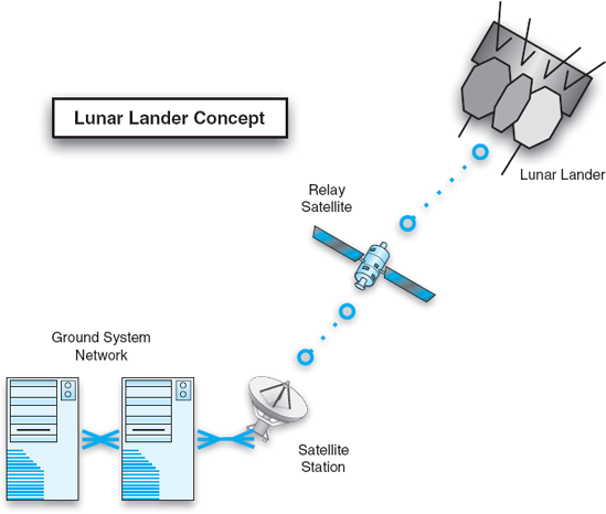
To illustrate how the DoDAF is used to model a system-of-systems, we present a Lunar Lander application modeled in a subset of the DoDAF viewpoints. An OV-1 view is a stylized graphical representation of the system's operation. It is a free-form overview of the application and important elements in it. The DoDAF views are not optimized for simple one-node systems like the basic Lunar Lander application we have covered in this book so far. However, in a more complex Lunar Lander system, communicating nodes such as ground stations, satellites, sensors, and so on might be depicted in such a view. Figure 16-1 shows an OV-1 view of a system-of-systems Lunar Lander example. Here, the Lunar Lander itself communicates with the ground utilizing a satellite to relay data to a satellite communication station, which in turn is connected to a ground station. This is the most conceptual and least rigorous DoDAF viewpoint; other OV products are less conceptual and more concrete.
Figure 16-2 shows another DoDAF OV view, an OV-4 "Organizational Relationships" view. This diagram shows the relationships among various organizations and suborganizations that are involved in a project. Here, the main space agency oversees various subagencies, with assistance from an oversight organization. One subagency, the Lander Crew, is expanded to show the individuals roles that are assigned to personnel within that subagency. Note that the OV-4 diagram primarily depicts the relationships between people and not technological artifacts. The blending of organizations, personnel, and technology typifies OV diagrams in DoDAF.


DoDAF SV views tend to be more technical in nature. Figure 16-3 shows an SV-1"Systems Interface Description" view. The nodes are intended to correspond to nodes shown in OV diagrams. This shows an initial breakdown of functional responsibilities among the nodes, as well as the interconnections between them. Many such SV-1 views can be created for the same system, depicting the system at different levels of abstraction or showing interconnections between individual functions on nodes, rather than just the nodes themselves.
DoDAF makes extensive use of what it calls matrix views, also known as "N2 diagrams." These views are generally depicted as tables. Both axes of the table are populated with an identical set of nodes. These nodes generally represent concrete elements such as systems, subsystems, hosts, or devices. Each cell in the body of the table represents a possible interconnection between two of the nodes. If the two nodes are connected, details about the connection are listed at the intersection cell; otherwise, the cell is left blank. A matrix view contains all possible connections between elements.
Matrix views are often directly correlated with graph (that is, box-and-arrow) views of a system. Each node in the graph is listed on the axes of the table, and each line on the graph corresponds to a filled cell in the body of the table.
Figure 16-4 shows one such diagram, an SV-3 "Systems-Systems Matrix" diagram. In this diagram, the nodes on the axes are drawn from the earlier SV-1 diagram shown in Figure 16-3. Nodes on the diagonal are grayed out; communication between a node and itself is not considered. Each remaining node describes information exchange from the node named on the vertical axis to the node named on the horizontal axis. Nodes where no information is communicated, or no link exists (for example, from the Ground Station directly to the Lunar Lander) are left blank. Here, as with other DoDAF diagrams, the amount of detail present is determined by the user. The diagram in Figure 16-4 is relatively simple, showing only the kind of data transmitted and the protocol used. However, the DoDAF standard lists many types of information that can go in each node: status, purpose, classification level (such as unclassified or secret), means (such as the kind of network or protocol used), interface standard, and so on.

DoDAF TV products focus on identifying and tracking the technical standards that will be used to implement the described system-of-systems. DoDAF assumes that many aspects of these systems will be implemented using reusable off-the-shelf components that conform to various published standards. TV products provide ways of identifying what those standards are.
A portion of a TV-1 diagram for the Lunar Lander is shown in Figure 16-5. The leftmost column of the table shows a number of areas in which standards apply. The second column shows subareas. The DoDAF and a partner specification called the Joint Technical Architecture (JTA) enumerate these areas. Each system or subsystem, drawn from the earlier SV-1 view in this case, is associated with standards drawn from these areas. Each system or sub-system can also be given an absolute or relative time frame in which it will comply with or leverage the standard. For example, in this diagram, the Ground Station, Satellite Station, and Lunar Lander are all running operating systems that conform to the POSIX standard (IEEE 2004). Not all subsystems must use all selected standards, of course. Here, the Ground Station communicates with the Satellite Station using XML, sent over a Fiber Distributed Data Interface (FDDI) physical network. Different standards (not shown here) would facilitate the communication between the Satellite Station and Lunar Lander subsystems.

DoDAF describes, in great detail, the breadth of information that can be captured in an architecture description. It also categorizes that information into viewpoints and, where appropriate, describes potential points of correspondence between viewpoints. While it introduces substantial complexity, this breadth is DoDAF's primary strength. In some sense, DoDAF can be seen as a huge checklist of items that may be useful to capture or think about in the development and modeling of a system's architecture. As with any modeling notation, users must decide for themselves the kinds of models to create, the level of detail, and so on. DoDAF offers some advice in this regard, discussing different uses for architecture models and the viewpoints that are (in whole or in part) applicable to that use. However, even with this advice, users must still decide how they want to use the DoDAF on a case-by-case basis.
DoDAF does not, in general, mandate any particular method or notation for documenting the various viewpoints. Therefore, its users can choose any subset of the viewpoints they want and document them using any notation or tool they want. To its credit, the DoDAF specification provides examples for each viewpoint, including UML examples. However, these examples rarely exercise all possible details that can be captured in a view. Following the examples too closely would result in a set of views that left out major details. To strengthen the connection between DoDAF and UML, the OMG has submitted a request for proposals for DoDAF UML profiles (Object Management Group 2005). However, UML is not ideal for all DoDAF viewpoints (UML has no tabular diagram that would work for the matrix viewpoints, for example). Users must select notations and then weigh the advantages and disadvantages of their selection. Choosing several notations will increase the difficulty of coordinating them. Selecting a single notation might leave out important details, or make some viewpoints cumbersome.
Takeaway Message. Compared to the leanness of IEEE 1471, DoDAF takes the same high-level approach but goes into much more detail. It is optimized for capturing the relationships among people, organizations, system design decisions, and technical standards for complex and composite systems. It provides users with an extensive amount of information about what sorts of things to capture when developing an architecture, but far less information about how to capture that information or evaluate the results. Additional extensions to the standard, such as the aforementioned mapping of DoDAF views to UML, can fill in this gap. Because of the wide scope of the standard, it may be difficult for users to identify the views that are important to capture for a particular system. Because of its specificity, it may give users a false sense of security—that everything has been covered when, in fact, there are some stakeholder concerns that are being short-changed. A remedy for this is to focus first on stakeholders and concerns (as IEEE 1471 suggests) and then identify which DoDAF views map onto these concerns.
The Open Group Architecture Framework (TOGAF)[23] (The Open Group 2003) is the product of an iterative collaborative effort by members of The Open Group, a collection of more than 200 companies and other organizations. TOGAF is an "enterprise architecture framework." It takes into account concerns beyond hardware and software, such as human factors and business considerations. Enterprise architectures tend to focus on organization-wide solutions to implement business goals. Elements in an enterprise architecture might include databases, applications such as spreadsheets and Web browsers, various client and server machines, as well as people in various roles. TOGAF borrows concepts and terminology from IEEE 1471; its notions of architecture, views, viewpoints, and so on are consistent with those discussed above in the context of IEEE 1471. Various versions of TOGAF have been developed over the years; each version has grown to encompass more aspects of architecture. TOGAF version 8 encompasses:
Business concerns, which address business strategies, organizations, and processes.
Application concerns, which address applications to be deployed, their interactions, and their relationships to business processes.
Data concerns, which address the structure of physical and logical data assets of an organization and the resources that manage these assets.
Technology concerns, which address issues of infrastructure and middleware.
TOGAF consists of three major elements: an architecture development process called the ADM (architecture development method); a "virtual repository" of architecture assets (such as models, patterns, and architecture descriptions) extracted from architectures developed in practice, called the Enterprise Continuum; and a resource base consisting of guidelines, templates, background information, and so on to assist enterprises in following the ADM.
The centerpiece of TOGAF is the ADM, a process for developing enterprise architectures. Like many other modern software processes such as spiral model-based processes (Boehm 1988) and RUP (Kruchten 2003), ADM is iterative, meaning that activities are visited and revisited, with each subsequent iteration refining decisions made in earlier iterations. It recommends a sequence of steps and activities that should be taken, but leaves much up to the implementing organization—how to scope the project, how to make decisions within those phases, and so on. As shown in Figure 16-6, there are eight primary phases of the ADM, beginning with Architecture Vision (which is an effort to lay out what will be done and align the organization with those goals). Subsequent phases proceed through the elaboration of various architectural concerns including those identified above, creating models along the way. For each concern, different views are prescribed as ways to capture aspects of those concerns. Some of those views map naturally onto, for example, UML diagrams, while others are defined more generally, similar to DoDAF views. Remaining phases focus on issues surrounding reduction to practice and the implementation of the decisions that were made in earlier phases. Technologies are selected, implementation projects are prioritized, and actual implementation efforts are managed, all of which are done in the context of the organization's assets, personnel, and capabilities. The final phase, Architecture Change Management, addresses assessment of previous efforts and deciding how and whether to proceed through another iteration of the process.


Figure 16-7. TOGAF Enterprise Continuum, consisting of the Architecture Continuum and the Solutions Continuum (redrawn based on TOGAF specification).
The second major part of TOGAF is the "Enterprise Continuum." The Enterprise Continuum acts as a repository of assets—architectural resources and known solutions. As such, it consists of two portions: the Architecture Continuum and the Solutions Continuum, as shown in Figure 16-7. Roughly, elements on the left side of the continuum are more technological and concrete; elements on the right side address business and organizational issues. Through the TOGAF Technical Reference Model and Standards Information Base, the TOGAF standard itself taxonomizes various types of components, services, and standards that can be found across the enterprise continuum. These include everything from command-line interpreters to programming languages to electronic mail and configuration management systems.
The third major part of TOGAF is the TOGAF resource base, which is a collection of useful information and resources that can be employed in following the ADM process. It includes advice on how to set up boards and contracts for managing architecture, checklists for various phases of the ADM process, a catalog of different models that exist for evaluating architectures, information on how to identify and prioritize different skills needed to develop architectures, and much more.
TOGAF is distinguished from other approaches by its large size and broad scope; the summary in this section only covers the major elements of the standard. TOGAF focuses on enterprise architecture, which is different in character from the kind of software architecture discussed in this book. Enterprise architecture is as much about the architecture of an organization as the architectures of its products. Elements in TOGAF architectures tend to be organizations, people, and large-grained assets (applications, platforms, machines, enterprise-wide services, and so on). Otherwise, TOGAF collects a large and diverse set of best practices for architecture. It prescribes not only an architecture development process, but defines a wide variety of views and concerns, as well as solution elements that can be used to satisfy those concerns.
Takeaway Message. TOGAF complements other architectural approaches by taking into account more business and organizational concerns. Its high-level approach, focusing on enterprise architecture, means that it is best used for dealing with coarse-grained elements and assets, constructing entire information systems and not just software applications. Like DoDAF, TOGAF provides a substantial set of best practices to follow and checklists to use for assessment, but individual users are responsible for the details. Following TOGAF helps to ensure thoroughness, but not necessarily quality.
RM-ODP (ISO/IEC 1998) is an ISO standard for describing open distributed processing (ODP) systems. Although the characteristics of ODP systems are described over several pages of the RM-ODP standard, they can generally be described as information systems developed to run in an environment of independent, heterogeneous processing nodes connected by a network. Primarily, the RM-ODP standard defines five viewpoints and describes associated viewpoint languages for documenting the architecture of an ODP system. These viewpoints are:
Enterprise: A viewpoint focusing on the system, its environment, and its surrounding context.
Information: A viewpoint focusing on information and information processing.
Computational: A viewpoint focusing on the architectural structure of the system and how different components or objects are distributed across hosts.
Engineering: A viewpoint focusing on the infrastructure required to support distribution.
Technology: A viewpoint focusing on technology choices for the system.
These viewpoints (and their associated languages) have various levels of concreteness. The computational and engineering viewpoints are more concrete and thus more constrained because they have the goal of helping to guarantee interoperability and portability of components. The enterprise and information viewpoints are more general, and therefore their languages are less constrained.

Figure 16-8 shows a sample RM-ODP enterprise view. Enterprise view elements include personnel and high-level application components, reminiscent of the kinds of elements addressed by TOGAF. The enterprise viewpoint looks at the system holistically, in terms of overall scope and its place inside the larger organization. Enterprise views can also describe agency boundaries—boundaries of responsibility or control.
In contrast, Figure 16-9 shows an example RM-ODP engineering view. This view shows how a ground system might communicate with a Lunar Lander via a complex communication channel implemented by two communicating network stacks. Here, the elements are more technologically oriented, and human elements do not appear. In general, both these views would be accompanied by text explaining the diagrams, the various elements, and their interconnections. The notation used above, with ovals and interconnections, is used in the RM-ODP specification but is not canonical: Many different notations (including, for example, UML) could be used to draw these diagrams.
Like DoDAF and TOGAF, RM-ODP focuses on what kinds of things should be modeled in an architecture, but not specifically how those things should be modeled. RM-ODP goes a step further than these two standards, however: Instead of prescribing a particular notation for each viewpoint, the RM-ODP specification prescribes a number of characteristics that a notation describing the viewpoint must have. Therefore, RM-ODP viewpoint languages are not languages in the traditional sense, but rather sets of requirements for languages. RM-ODP does include a separate specification describing, at a very high level, how various formal specification languages [for example, LOTOS (ISO 1989), Z (Spivey 1988), or SDL-92 (Telecommunication Standardization Sector of ITU 2002)] could be used to describe architectural semantics for RM-ODP architectures. Here, it lists an RM-ODP concept, and then identifies a formal specification language concept that could be used to implement that concept. This level of correspondence is not enough to give users serious guidance as to how to leverage these formal specification languages to implement RM-ODP.

Takeaway Message As a standard, RM-ODP is very similar to DoDAF, although the number of viewpoints is more limited and focused. Like DoDAF, an architecture specified according to the RM-ODP standard may or may not achieve certain qualities; the primary value added by RM-ODP is to ensure that architects think about and document certain aspects of architecture that impact various qualities—distributability, interoperability, and so on. It is eventually up to the architects to actually ensure those qualities. Although some mappings between RM-ODP concepts and formal methods are specified, there is a large gap between them that must be bridged by individual users. This gap is too large to assert that RM-ODP is particularly supportive of formal analysis activities.
Notational standards define standard notations for writing down design decisions. Notational standards can be used to realize/implement certain elements of conceptual standards; for example, a notation such as UML can be used as a way of documenting the various DoDAF views. In a way, any codified architecture description language, such as those surveyed in Chapter 6, could be viewed as a de facto notational standard. In this section, we examine notations that have actually gone through a standardization process or committee and that have gained notoriety or use because they are standards.
We have covered various aspects of UML (Booch, Rumbaugh, and Jacobson 2005) throughout earlier chapters of this book: its notation, its visualizations, its metamodel (Object Management Group 2002), and so on. This section will focus on UML as a standard and describe its advantages and disadvantages from that perspective.
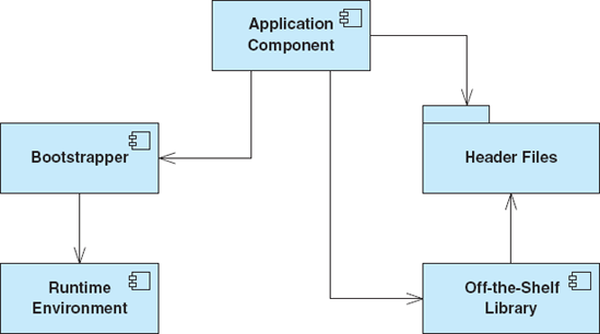
UML provides a standard syntax for describing a wide variety of aspects of software systems. Basic UML (without extensions) prescribes very few semantics to go along with this syntax. It is possible for the same element or diagram to mean entirely different things. For example, the dashed arrow connector in UML indicates a dependency between two linked elements. That dependency could mean "needed to build" or "plugs-into" or "calls." There is no way, without additional context or information, for a stakeholder to look at a dependency arrow in UML and have any clear idea what it means. This situation is depicted in Figure 16-10—the dependencies are all specified but the reader knows little about them.
UML that follows only the basic standard establishes a common symbolic representation of elements and their relationships. The fact that a system is described in UML implies little about the quality of that system—good designs can be documented in UML as easily as bad ones.
UML's value can be substantially increased through the use of UML extensions and profiles. Recall that a UML profile is a coordinated set of extensions to UML. In a way, UML profiles are themselves standards that specialize the base UML standard for different domains. OMG, the organization that manages the UML standard, also manages a number of de jure standard UML profiles, including profiles for CORBA systems, enterprise application integration, and system engineering. The latter, called SysML, is discussed below.
Profiles may include stereotypes, tagged values, and constraints. UML stereotypes allow users to specialize existing UML symbols to add project- or domain-specific semantics. Stereotypes can specialize the dependency arrow to mean <<calls>> or <<needed-to-build>> or <<plugs-into>>. For example, Figure 16-11 shows the same UML diagram as Figure 16-10, except the dependencies are stereotyped. This diagram is much more readable and provides substantially more information. To be fully useful, however, a UML profile for a project must be accompanied by detailed documentation explaining when and how to use the various stereotypes, tagged values, and constraints, as well as their meaning. With the proper use of profiles, a UML description becomes a valuable tool for stakeholder communication and system understanding, and also has positive impacts on traceability and analyzability.

Even with profiles, however, UML and its accompanying tools are (currently) not well-suited to the verification of specific quality properties. Will the described system satisfy its requirements? Be efficient? Be cost-effective? Be free of deadlock? To determine answers to questions like these, additional methods above and beyond UML, ranging from inspections to testing to formal verification, must be integrated separately into the development process.
Takeaway Message. UML is not a panacea for architecture-based software development. UML provides a set of common, symbolic notations for architects to write down and communicate certain kinds of design decisions. The diagram types that have been provided in UML allow architects to model a wide variety of concepts, although there are certainly architectural design decisions that cannot be easily captured in UML. UML profiles should be used to improve the rigor and understandability of UML diagrams, but profiles have their limits. Profiles can decorate existing diagrams, but they cannot create entirely new diagrams. Modeling a system in UML makes few guarantees about that system—UML can be used to document both good and bad architectures (although UML does make it easier to understand, communicate about, and evaluate architectures).
Despite the wide variety of modeling concepts supported in UML, different engineering efforts require even more modeling breadth. A good example of this is SysML (SysML Partners 2005). SysML is an effort by a coalition of more than twenty engineering organizations (primarily corporations, but also universities and other organizations) (SysML.org 2007) to customize UML for systems engineering. With respect to standardization, the SysML community has taken an interesting two-pronged approach. One group is developing and promulgating an open-source version of the SysML standard under a license that allows users to redistribute and modify SysML on their own. From this open-source version, an official OMG standard version of SysML has been created. "OMG SysML" is trademarked, and evolves, like UML, through the standards committees and processes of the OMG.

Many individuals and organizations perceive UML to be too software-biased for modeling systems engineering concerns that include elements such as hardware, networks, development organizations, and so on. Of course, many UML diagrams can be interpreted in ways that do capture these concerns (for example, a traditional systems engineering block diagram closely resembles a class diagram in many ways). SysML includes a subset of UML, but also extends it. Diagrams reused from UML are the activity, class, composite structure, package, sequence, state machine, and use case diagrams. Two of these diagrams are renamed for SysML: Class diagrams are called "block definition" diagrams and composite structure diagrams are called "internal block" diagrams. SysML also adds stereotypes to UML as well as two new diagram types: requirement and parametric diagrams. Requirement diagrams show system requirements and their relationships with other elements. Parametric diagrams show parametric constraints between structural elements, which are useful for performance and quantitative analysis.
Figure 16-12 shows a SysML requirement diagram for the Lunar Lander application. This diagram shows only requirements and their relationships; a more complex requirement diagram might actually include additional detail for each requirement such as the actual text describing the requirement, a unique ID, and so on. Requirement diagrams can also be used to associate requirements with elements from other diagrams such as use cases. Syntactically, requirement diagrams primarily reuse and specialize elements from class diagrams, using stereotypes on classes and relationships to make those elements specific to requirement diagrams.
Figure 16-13 shows a SysML parametric diagram. Parametric diagrams are specializations of SysML internal block diagrams—composite structure diagrams in UML. These diagrams allow architects to associate quantitative parameters with various model elements. These parameters can then be associated with mathematical models, equations, or analysis techniques that can be used to evaluate or assess parts of the system quantitatively. For example, several state-storage elements (the Clock, the Lander State) provide values to the next-state equation, which is used to calculate the next state of the Lunar Lander simulation.

The development of SysML is consistent with our earlier assertion that UML is not necessarily a complete solution for architectural modeling. The SysML developers left out certain UML diagrams they believed were extraneous or unnecessary, and added new diagrams that were missing. SysML has not been as universally supported or adopted as UML, despite the fact that it is not a radical departure from traditional UML 2. Tool support in the form of modeling environments, for example, has lagged behind UML, and while some UML modeling environments such as Telelogic Rhapsody have some explicit SysML support, many others do not. This indicates that even a large group of influential organizations cannot necessarily force the adoption of any particular standard. Note also that even the new SysML diagrams reuse and overload existing UML symbols, likely a compromise to provide some degree of modeling support in tools that are notSysML-aware.
Takeaway Message. SysML is an example of how standards can evolve, change, and fork apart. By reusing substantial parts of the UML standard, the SysML partners were able to save a tremendous amount of effort as well as allow users to apply their existing UML knowledge in a systems-engineering context. However, the changes and extensions they made to UML—conservative as they are—have been a double-edged sword. On one hand, they provide increased expressiveness for systems engineers. On the other hand, they have reduced the amount of tool support that exists for users. Even standards that are supported by a substantial amount of influential organizations must still win many hearts and minds on technical and business merits to achieve widespread success.
Many organizational cultures will standardize on a particular tool as much as (or more than) more abstract approaches. Corporations often evaluate a spectrum of tools and then purchase one (or a small number) of them in bulk, and that tool becomes mandatory for use within the company. Standard tools tend to be de facto standards, because they generally are developed and controlled by a single organization.
The wide adoption of the UML standard generally induces organizations to adopt one or more standard tools for working with UML. This is often motivated by a desire for consistency and interoperability across an organization, as well as market pressures: Organizations buying tools from a single vendor can often get volume discounts and negotiate enhanced support agreements. UML itself, however, is not bound to any particular tool. Tools that have become de facto standards for UML editing include IBM's Rational Rose (Rational Software Corporation 2003), Microsoft Visio (Microsoft Corporation 2007), Telelogic System Architect (Telelogic AB 2007), ArgoUML (Argo/UML), and others.
These tools vary in their exclusivity of support for UML. Tools such as ArgoUML and Rose focus their support almost exclusively on UML, while tools such as Visio and System Architect support diagrams in many notations. All the tools support the creation and manipulation of UML diagrams, generally through a point-and-click graphical interface. The form of this interface—what menu options are available and so on—depends on the individual tool. UML does not standardize how users are to interact with these diagrams. For example, Rose uses a tree-based view to organize diagrams within the model and property sheets to decorate various model elements.
The tools differ widely in their support for additional capabilities beyond plain UML modeling: design aids, artifact generation, constraint analysis, and so on. Sometimes, third parties will create plug-ins for the tools that add additional features.
A generic diagramming tool such as PowerPoint can be (and often is) used to create UML diagrams, even though it has no specific understanding of UML's (graphical) syntax and semantics. These tools, then, cannot provide any guidance to UML users to help create consistent or complete documents. UML-aware tools, on the other hand, provide design guidance as users create and edit UML. These features include:
Support for UML's built-in extension mechanisms: Recall that UML profiles allow users to specialize elements and introduce additional commonalities among them. UML tools may allow a user to define stereotypes and manage associated tagged values, applying the stereotype's tagged values to all elements of the stereotype, for example. The user interface may also provide new options when stereotypes are applied: The visual appearance of an element may change (adding an icon, for example) and new options may be presented to the user to manipulate the properties associated with that stereotype.
Support for consistency checks: The ability to specify and automatically check constraints can increase stakeholders' confidence in the quality of the architecture. Most UML tools guide the user in making syntactically correct UML documents. The syntactic constraints of UML are generally basic well-formedness checks—that links have valid endpoints, or that two elements do not have the same name, for example.
Many tools go further, and allow the user to check semantic and cross-diagram consistency constraints. For example, a tool may warn a user when a sequence diagram indicates an invocation on an object whose class does not implement a method with the same name as the message. Not all of these constraints are necessarily part of the UML standard, but they are commonly accepted conventions about particular relationships in UML and help to increase the internal consistency of UML models. One danger in this regard is that users of a particular tool may not be able to distinguish easily which constraints are part of UML itself, and which are just being enforced by the local tool.
Beyond these generic syntactic and semantic checks, UML includes a constraint language, OCL (Warmer and Kleppe 1998), that allows users to specify constraints on UML elements and element relationships. Tools are available that can assist users in specifying OCL constraints, and then check them automatically. UML does not mandate the use of OCL as its only constraint language, however, so it is possible for UML tools to incorporate additional constraint languages.
Generation of other artifacts: UML models can be used as the basis for generating artifacts useful in other life cycle activities, such as implementation or testing. Some UML tools include facilities for generating these artifacts, or parts of them. For example, Rose has an internal tool called SODA that focuses on the generation of other artifacts from Rose models. SODA effectively transforms UML models into other formats using user-definable templates. Different templates will transform UML models into different kinds of artifacts: One template may output documentation in a Microsoft Word file; a different template may take the same UML model and generate code skeletons for each of the defined classes. Automatic generation of artifacts that are important in non-design phases of the software engineering life cycle (such as code artifacts for the implementation phase) is especially useful in preventing architectural drift and architectural erosion.
Generation of UML: Some UML tools can take other artifacts (usually implemented systems) and automatically generate partial UML models for them. For example, some tools can iterate over a series of Java classes and automatically generate a corresponding class diagram. These inferences are not always 100 percent correct or useful. They may fail to make inferences about dependencies between classes because a mechanism such as dynamic class-loading or reflection is used. They may also generate every class dependency, when only some of them are architecturally important. For this reason, automatically generated UML needs to be reviewed and "tuned" by hand.
Traceability to other systems: Generation is not the only connection that UML tools may use to interoperate with other artifacts; traceability and links can be used as well. Linking mechanisms may be provided to connect UML elements with system requirements in a requirements management environment such as Telelogic DOORS(Telelogic DOORS), with configuration management repositories, with code-based integrated development environments, with simulation environments, and so on. When such links are available, additional consistency constraints can be checked as well. This can extend the scope of a UML modeling environment beyond UML itself and incorporate other architectural (and nonarchitectural) concerns into the modeling process.
Takeaway Message. UML tools have a profound effect on how users experience modeling in UML. While all tools provide basic support for drawing UML diagrams, the real value in the tools often comes from features provided above and beyond basic drawing: checking additional constraints above and beyond "plain" UML, customizability, generation of other artifacts, reverse engineering code, traceability to other artifacts managed in different environments, and so on. These features generally automate processes that would otherwise be tedious, manual, and error-prone. It is important to be cognizant of any differences between the standard UML language and peculiarities or limitations introduced by specific UML tools. Also, UML tools may lag behind the latest developments in the UML standard itself.
Telelogic System Architect (formerly Popkin System Architect) (Telelogic AB 2007) is a popular tool among system engineers. It is used to manage diagrams of many different views of a system in multiple diagrammatic styles. It has support for more then fifty different types of diagrams drawn from different modeling methodologies—all the UML diagrams, IDEF, OMT, generic flowcharting, and more. Beyond the basic System Architect tool, a number of variants are also marketed: for DoDAF, for Service Oriented Architectures, for designing enterprise-resource planning (ERP) systems, and so on.
System Architect can support this wide breadth of diagram types because of its internal construction. Internally, diagram data is stored in a relational database that is updated as the user creates and manipulates diagrams. Each diagram type is associated with a particular vocabulary of symbols and interconnections, as well as constraints that assist the user in creating syntactically correct diagrams.
System Architect is an example of a "standard" tool that trades semantic strength for breadth. It can be viewed as a very good domain-specific diagram editor. That is, it has specific support for drawing diagrams with the syntax of UML, IDEF, OMT, or any number of other types of diagrams. However, it has little understanding of the semantics of these diagrams. The specialized versions of the product (for example, System Architect for DoDAF) have some additional semantic knowledge built in such as the ability to generate or check the consistency of different diagram types.
Takeaway Message. Telelogic System Architect is a de facto standard, flexible drawing tool that gives users a plethora of diagram types in which to express architectural decisions. On one hand, the construction of the tool makes it very easy for Telelogic to incorporate new diagram types and adapt to new diagrammatic languages and standards that emerge. However, this comes at the cost of having more limited associated support for the semantics of those notations. In System Architect, it is certainly easier to draw diagrams with complex syntactic vocabularies than in a completely generic tool like PowerPoint, but it provides little guidance to users as to the quality, correctness, or consistency of their architectures.
The standards we have covered thus far are mostly related to how to capture an architecture, either conceptually, in a specific notation, or using a particular tool. Process standards dictate the process—that is, the steps—that are used to develop software. These standards focus less on artifacts and more on the methods used to create them.
The Rational Unified Process (RUP) (Kruchten 2003) is a standard that was created by the Rational Software Corporation, now IBM. Fundamentally, the RUP is an iterative process, and is inspired by Barry Boehm's spiral model (Boehm 1988). Rather than prescribing a single, concrete sequence of steps to follow when developing software, the RUP is an adaptable process framework, intended to encompass many different iterative processes and to be tailored for each of them. RUP describes software construction as a whole and is not focused primarily on architectural development (like TOGAF's ADM).
A RUP project is done in phases. The RUP identifies four specific phases:
Inception phase: The inception phase includes initial activities that determine the goals and success criteria for an iteration; it includes making a business case, describing basic use cases, assessing risks, establishing budgets, and so on.
Elaboration phase: Here, use cases are further elaborated and architectural design decisions are made to satisfy them. Business plans and risk assessments made in the inception phase are refined and revisited. Prototypes may be developed.
Construction phase: This phase largely encompasses the implementation and construction of elements that are designed and specified in the elaboration phase.
Transition phase: In this phase, the developed product is transitioned to the end users. It is validated and tested, and its functionality and quality are assessed against the goals set in the inception phase. Deployment, installation, and training are performed in this phase.
The goal of each phase is to reach a milestone. For example, the inception phase ends with the "Life Cycle Objective Milestone," which requires stakeholder agreement on scope, cost, and schedule, elaboration of high-level use cases, agreement on credible risk assessments, and so on. Internally, each phase consists of smaller activities apportioned to various personnel. These activities are broken up by disciplines such as requirements, design, implementation, testing, and so on. Iterations of these activities may occur within each phase. While the inception phase is expected to be short and is usually done in a single iteration, the other phases often involve multiple iterations.
Figure 16-14 shows the relationship among phases, iterations, and disciplines in a hypothetical instance of RUP. Time proceeds from left to right. Note how the development effort is partitioned by the phases and iterations occur within each phase. The dotted breakpoints between the phases indicate milestones that must be reached. Although all disciplines may be addressed during each phase/iteration, some disciplines are more prominent than others in different phases. For example, very little implementation occurs in the inception phase (perhaps proofs-of-concept or initial prototypes), while a large amount occurs during the construction phase. Likewise, requirements are a heavy focus during inception but are only revised and refined during the construction phase.

Figure 16-14. Rational Unified Process phases, iterations, and disciplines (adapted from Kroll and Kruchten, The Rational Unified Process Made Easy: A Practitioner's Guide to the RUP).
Takeaway Message. Ever since the development of the spiral model, software engineers have widely recognized that the use of iteration and risk analysis are important. RUP is a meta-process or process framework in which many iterative (and linear) processes are instances. For example, one could view the traditional waterfall model as a single-iteration instance of RUP. RUP has a tendency to view architecture as a design artifact, rather than as a pervasive discipline—as we have advocated in this book—but the two notions are not entirely incompatible. RUP is not necessarily a universal meta-process; certain development strategies such as Extreme Programming or Domain-Specific Software Engineering may have more lightweight and fluid processes that do not fit naturally in a structured, iterative RUP model.
Model-Driven Architecture (MDA) (Mukerji and Miller 2003) is a methodology standardized by the Object Management Group (OMG), the same body that manages the UML standard. MDA aims to reconceptualize system development by leveraging the development of models that are refined, through a series of transformations, into implemented systems. Confusingly, the word "architecture" in Model-Driven Architecture does not refer to the architecture of the system under development, but rather to the architecture of the various standards and languages that are used to implement the MDA approach. Synonyms for MDA include Model-Driven Development (MDD) and Model-Driven Engineering (MDE); "MDA" is generally used to refer specifically to the OMG approach.
Figure 16-15 shows a high-level overview of MDA. In MDA, systems start out by being described in platform-independent models (PIMs). These PIMs describe the application without binding it to specific implementation technologies; any number of languages may be used for this purpose, particularly domain-specific languages. Then, a platform-definition model (PDM) is used to specify the target platform for system implementation. This may be based on some middleware or component-based implementation technology such as CORBA, .NET, JavaBeans, and so on. By combining the application knowledge in the PIM with the platform knowledge in the PDM, one or more platform-specific models (PSMs) are created. These PSMs are part of a system implementation in a domain-specific implementation language or a general-purpose programming language such as C or Java.
Ideally, once the PIMs and PDMs are defined, the rest of the translations can occur using (or at least leveraging) automated translation tools. The separate OMG Queries/Views/Transformations (QVT) standard is one way of defining model transformations. Assuming the translations are correct and preserve salient properties, the result of MDA should be a system that is faithful to the original models.

Takeaway Message. As a general approach, MDA is compatible with many of the mechanisms and ideas espoused in this book. For example, Chapter 9 on implementation discusses how generative technologies can be used to automatically generate (partial) implementations from architectural models, especially when an architecture implementation framework is used. The idea behind MDA is easy to grasp, but the practical details are somewhat more elusive. Making automated transformations from models into implementation artifacts is difficult. Developing completely platform-independent models of an application also is hard to do, since knowledge of available implementation technologies always informs and constrains architectures. MDA is much easier to employ in the context of DSSE, where a well-understood and constrained domain, reference architectures, and existing frameworks provide a much better-elaborated foundation.
This chapter has attempted to provide high-level overviews of some of the most popular and well-known standards used in practice. One thing that is not evident from this chapter is the level of detail at which many of these standards are specified. Specifications for some of the standards exceed the length of this book, and supplemental books (and, in some cases, book series) have been written to help people understand and apply these standards.
Size is rarely a good way to assess the value of a standard, however. For example, it stands to reason that large, detailed standards provide an immense amount of guidance, and indeed this is often the case. However, what kind of guidance do they provide? Often, large standards remain underspecified: They give the user too much freedom or too many options, often in an attempt to broaden their appeal or applicability. Many of the largest and broadest standards (for instance, DoDAF, TOGAF) prescribe extensive processes and checklists. These are often impossibly detailed—a project that attempted to satisfy every requirement or piece of advice in these standards would never get around to actually building a system. Furthermore, deciding correctness and consistency is an exercise most often left up to the system developers, with little guidance from the standards.
When using a standard, a developer or organization must always keep in mind the costs and benefits of the standard. Looking for and exploiting network effects should be a priority of anyone employing a standard. Some standards exploit network effects better than others. For example, a standard like UML is well supported by mature tools because of its large user community, and UML models can be used to more efficiently communicate ideas among different people and organizations because of common understanding of the meaning of different symbols. However, a process standard may have less network effect: The value of the process does not necessarily increase simply because more organizations use the it, unless improved tool support or process refinements are a side effect of that use.
The standards in this chapter document many best practices—well-worn techniques that have been successfully used on projects in the past. Following any of these practices is undoubtedly better than a completely ad hoc development, and the standards at least provide a yardstick against which completeness or comprehensiveness can be measured. Many important decisions, such as when enough modeling has been done, or what specific process to follow, or how to define individual project goals still must be made on a case-by-case basis. More specific and detailed guidance will not be found in the most generic (and unfortunately, well-known and well-supported) standards. Developers may have more luck combining the breadth of generic standards with more specific domain-specific standards—if such standards exist.
Standards are a big part of using software architecture in practice: Their creation, development, and use are motivated as much by business and organizational goals as technical ones. In the next chapter, we continue the theme of software architecture in practice by focusing on organizational concerns: people, roles, and teams.
What is a standard?
What is the difference between a de facto and de jure standard?
What is a network effect? How do standards help to create a network effect?
What are some drawbacks of standards?
What are the advantages and disadvantages of adopting a standard early? What are the advantages and disadvantages of adopting a standard late?
What is the scope of IEEE 1471? How does it advise and guide users?
Describe DoDAF. How does DoDAF help its users? What does DoDAF not provide?
What is TOGAF and how does it differ from DoDAF? What is the difference between enterprise architectures and software architectures, as they have been described in this book?
What are the five RM-ODP viewpoints? What kinds of systems is RM-ODP targeted for?
What are UML profiles and how do they help users in applying the UML standard?
What is SysML and how does it differ from UML?
What lessons can be learned from the standardization efforts behind ADML and AADL?
Enumerate some standard architecture tools. How do standard tools augment standard notations? How can they hinder the use of a standard notation?
Enumerate some process standards. How do process standards augment and interact with other standards?
Obtain and read one of the standards listed in this chapter. Choose a system with which you are familiar (or one of the ones used as an example in this book, such as Lunar Lander or the World Wide Web) and outline how it would be described or implemented using that standard. Identify the standard's strengths and weaknesses in the context of your experience.
Draw out and discuss the relationships between the standards discussed in this chapter. Are they mutually exclusive? Do they dovetail with one another? Are they sequential? Identify some software development standards not discussed in this chapter and add them to your diagram.
Find an architectural model that claims to conform to one of the standards in this chapter. Check it for conformance against the standard itself.
Choose a standard and investigate how it is described and marketed by its creators and others. Assess whether the benefits (and drawbacks) claimed of the standard are accurate or not.
Contact one or more software development practitioners and find out about their use of standards. Ask what benefits they believe they are deriving from the use of the standard, and assess whether their development experiences have borne these out.
Find a tool set that purports to support a particular standard. Select various elements of the standard and determine how they are supported by the tool set. Identify how the tools help or hinder the use of the standard.
This chapter attempts to distill and extract the essence of some of the most well-known and influential standards in software engineering today. Still, the few pages dedicated to each standard cannot capture the scope of most of them. As noted above, the length of several of these standards exceeds the length of this book.
The best way to learn about a standard is often to go to the source. References are included in the for IEEE 1471 (IEEE-SA Standards Board 2000), DoDAF (DoD Architecture Framework Working Group 2004), TOGAF (The Open Group 2003), RM-ODP (ISO/IEC 1998), UML (Booch, Rumbaugh, and Jacobson 2005) and its meta-model the MOF (Object Management Group 2002), SysML (SysML Partners 2005), AADL (Feiler, Lewis, and Corporation 2003), ADML (Spencer 2000), Rational Rose (Rational Software Corporation 2003), Telelogic System Architect (Telelogic AB 2007), RUP (Kruchten 2003), MDA (Mukerji and Miller 2003), and others. Beware of the "executive summaries" contained in some of these standards or related documentation; these descriptions are often heavy with hype and it is difficult to get a clear assessment of a standard from them. For comparative purposes, it might be useful to examine standards not related to architecture such as POSIX (IEEE 2004) and HTTP (Fielding et al. 1999) or domain-specific standards such as the Software Communications Architecture (SCA) (Modular Software-programmable Radio Consortium 2001), introduced in Chapter 15.