
Lesson Files | Motion3_Book_Files > Lessons > Lesson_04 |
Media | Motion3_Book_Files > Media > News_Teaser |
Time | This lesson takes approximately 60 minutes to complete. |
Goals | Use the Compass, Camera menu, and 3D View tools |
Navigate and orient the camera using multiple viewports | |
Add and position layers in 3D space | |
Work with lights | |
Animate a camera with behaviors | |
Use the Walk Camera tool | |
Animate a camera with keyframes |
Now that you have a sense of how 3D works in Motion, you can embark on the next step: moving around in this new world.
Whether you are moving a camera to look at layers from a different angle or switching to a different view to see the camera in relation to the objects in a scene, Motion provides navigational tools that make it easy to orient your view and your camera in 3D space. You can then precisely animate the camera through the 3D scene.
In this lesson, you’ll explore 3D overlays that allow you to look at and navigate through Motion’s 3D world. You’ll place objects in this 3D world, add and modify lights to illuminate the world, and animate the camera using behaviors and keyframes.

You can easily get lost when working in three dimensions on a 2D screen, but Motion has a set of tools, hidden by default, that can orient you for navigating through the 3D world.
Open Motion3_Book_Files > Lessons > Lesson_04 > Lesson_04_Start. Choose File > Save As, and save the file in the Student Saves folder as Storm Watch Promo.
Press F5 to open the Project pane.

This is the same Action News 2 logo that you worked with in Lesson 3.
In the Layers tab, select the Camera.
Press F1 to go to the Properties tab of the Inspector. If necessary, click the disclosure triangles for Position and Rotation to display all three sets of parameters.
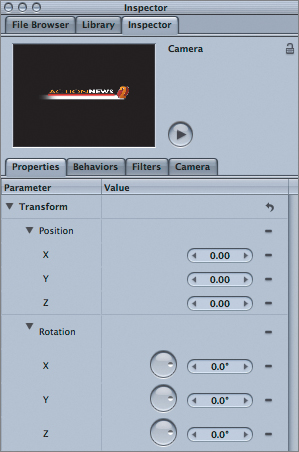
The zero values for all the parameters indicate that the camera is in its default orientation. But how can you be sure that what you are looking at in the Canvas is the camera’s view?
The 3D Overlays tools give you more information and let you manipulate the scene in 3D space.
At the top right of the Canvas, click the View and Overlay Options menu.

In the Show 3D Overlays section, there are five overlays: 3D View Tools, Compass, Inset View, 3D Grid, and 3D Scene Icons. Selecting an overlay activates it and adds a checkmark next to its name. Selecting the Show 3D Overlays section makes all active overlays visible in the Canvas.
Make sure there is a checkmark next to 3D View Tools only, and then select Show 3D Overlays.

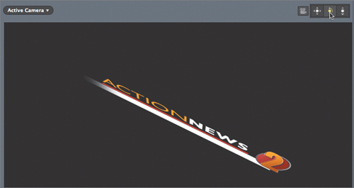
As long as a camera is present in your project, two new sets of controls appear in the Canvas. The menu at the top left is the Camera menu, and the controls at the top right are called the 3D View tools. The camera icon next to the 3D View tools indicates that they control the camera.
The Camera menu confirms that you are currently looking at the project through the active camera. You’ll come back to the Camera menu in a moment.
In the 3D View tools, drag the tool on the left, next to the camera icon.
This is the Pan tool, and it moves the camera up/down and left/right, very much like the Move XY (middle) control in the Heads Up Display (HUD).
Double-click the Pan tool to reset the camera.
Drag the middle tool, the Orbit tool. Double-click to reset it.
The Orbit tool works much like the Rotate XYZ control in the HUD.
Drag the tool on the right, the Zoom tool. Double-click to reset it.
The Zoom tool works like the Move Z control in the HUD.
So if the 3D View tools do much the same things as the HUD controls, why use them? The answer lies in the Compass.
Click the View and Overlay Options menu and select Compass.
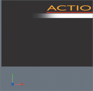
The Compass, with its red, green, and blue arrows, appears at the bottom left of the Canvas. You can see by looking at the Compass that the camera is facing directly down the blue Z-axis.
Move the pointer over the Compass; it changes to the 3D View Selector, where you can select from the view options. Click the green view icon to switch to Top view.

The Compass and the view rotate to look at the project from above.
Click the View and Overlay Options menu and choose 3D Scene Icons.

You now see an icon for the camera in the Canvas, and an outline of its angle of view and focal plane, which is resting right on the Action News 2 logo.
Notice that the Camera menu at the top left of the Canvas now says Top, instead of Active Camera.
Look at the 3D View tools at the top right of the Canvas. Notice how a camera icon is no longer next to them.
Drag the 3D View tools to pan, orbit, and zoom the scene.

You are changing the current view, but you are not changing the camera’s view at all. This feature allows you to see objects in the Canvas and their relationships to the camera.
In the HUD, drag the Rotate XYZ control. Then press Command-Z to undo.
The HUD still controls the camera. So, you can use the 3D View tools to control the current view, while using the HUD to change the camera’s view.
Sometimes you want to look at your virtual world from more than one perspective to understand what is happening in it. It may not seem necessary for the simple graphic in this exercise, but as you add many elements in 3D space, it can be extremely helpful to look at the scene from more than one angle at a time.
Click the View and Overlay Options menu and select Inset View.
Nothing changes in the Canvas, yet.
In the HUD, drag the Rotate XYZ control.
At the bottom right of the Canvas, the Inset view appears while you drag; it shows the camera’s point of view. You can see how the camera relates to the objects in the scene in the main view, and see how the camera views the scene in the Inset view. In the Inset view, notice the grid with red and blue axes.
Press Command-Z to undo the camera move. Click the View and Overlay Options menu and select 3D Grid.

The grid becomes visible in the Canvas. Notice how the red and blue lines are parallel with the red and blue axes in the Compass.
The grid is the “floor” of your virtual world. The blue line represents the Z-axis and the red line represents the X-axis. Where is the green Y-axis? Well, that axis is vertical, pointing straight up from the point at which X and Z meet, so it isn’t part of the floor—the floor consists of just the X-Z plane.
In the Camera menu, notice that the word Top now has an asterisk next to it. This is because, although you started with the Top view, you modified it with the 3D View tools. You can reset the view using the Camera menu.
Click the Camera menu.

The menu is organized into three sections:
The top section lets you choose a camera. You can have multiple cameras in a project and cut between them.
The middle section lets you choose a view, just like you do when using the Compass.
The bottom section lets you adjust the current view.
Select Reset View.
The Canvas now shows the original, unmodified Top view.
Note
If you didn’t undo the last camera move, click the reset button, which is the hooked arrow at the top of the Properties tab of the Inspector.
Rather than relying on the Inset view to see the active camera view—which is available only when making adjustments—you can split the Canvas into multiple viewports to have several views at all times.
At the top right of the Canvas, click the far right menu, the 3D View Options menu.
Here you have seven options for splitting the Canvas into different viewport arrangements. You can open as many as four viewports at once.
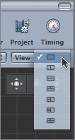
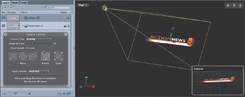
Choose the third option to display two viewports split horizontally.

The Canvas splits, with the upper half showing the current Top view, and the bottom half showing a different view. The yellow outline around the upper view indicates that it is the active view.
Use the Camera menu to switch the upper view to the active camera.
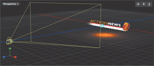
In the lower view, click the center of the Compass to switch to the Perspective view, and then use the 3D View tools to zoom back and pan to see both the logo and the camera.

You now have a layout with two viewports to make it easier to set up and animate the camera.
You’ll reposition the camera to look straight down at the logo—that may seem odd, but it will make sense shortly.
You’ve used the HUD and the 3D View tools to navigate the camera; now you’ll use the controls connected to the camera in the Canvas. You can manipulate the camera just as you moved the layers in the previous lesson. You’ll then add a map below the logo, so that the camera has something to look at.
If necessary, in the Toolbar select the Adjust 3D Transform tool.
In the Canvas, click in the lower view to make it active. In the Layers tab, select the Camera.

The Move and Rotate controls for the camera appear. You can drag the red, green, and blue arrows to move the camera along the X, Y, and Z axes. And you can drag the white hollow circles to rotate the camera around the X, Y, and Z axes.
Notice that these controls are located at the focal plane of the camera. This is because the anchor point for a framing camera, which is the default camera type, is always located at the center of the camera’s focal plane.
You want to start out with the camera pointing straight down from above the text.
Holding down the Shift key, drag the top rotation circle up to rotate the camera around the camera’s red X-axis to 90 degrees.
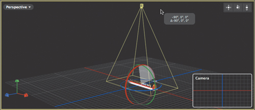
The Shift key snaps the rotation to precise 45-degree increments. The result is visible in the Inset view as you drag, and in the upper camera view after you finish.
Note
It’s important to hold down the Shift key before you start to rotate the camera; otherwise, the snapping will add 45 degrees to the starting rotation value. So if you rotated 10 degrees, then pressed Shift, it would snap to 55 degrees, 100 degrees, and so on.
The logo, a 2D object in 3D space, appears as a thin white line along the grid’s red X-axis. The white line is there only to help you identify the location of the object. It won’t be visible in the rendered movie.
With the camera in its starting position, you can add the map graphic.
In the Canvas, choose the upper Active Camera view.
In the Layers tab, click the Add (+) button to create a new group, and name it Map.
Press Command-1 to open the File Browser, navigate to Motion3_Book_Files > Media > News_Teaser, and locate Map.png.
Drag Map.png to the Map group in the Layers tab.

Notice how the map is automatically oriented in the same plane as the Action News 2 logo. That would be really convenient if it were what you wanted, but in this case it’s not.
Press Command-Z to undo.
Drag Map.png from the File Browser to the center of the Active Camera view in the Canvas. Position it in the center of the Canvas and release the mouse.

By dragging an object directly to the Active Camera view in the Canvas, it is automatically placed at the focal plane of the camera. This is extremely useful because you can move the camera to the location you want, then start adding objects to the scene, and they automatically will align to the camera.
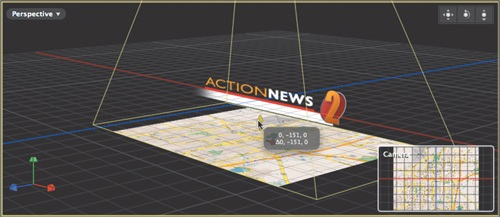
In the Perspective view, you can see how the map intersects with the logo, but you want it to be below the logo.
In the Active Camera view, drag the center blue arrow left and watch the tooltip to move the graphic down about 150 pixels.

Note
In the tooltip, you may notice that the second value, the Y value, changes as you drag. But you are dragging on the Z-axis. What’s going on? The tooltip’s axes are based on the World view, and if you look at the grid, you’ll see that moving the graphic down is actually moving it along the world’s Y-axis. The center axis on the graphic is blue because, in the HUD, the Adjust Around pop-up menu is set to Local Axis.
Since the map is now farther from the camera, you’ll need to move the camera toward it.
In the Layers tab, select the Camera.
In the Perspective view in the Canvas, drag the blue Z-axis arrow down by the same distance you moved the graphic—about 150 pixels.
With the graphic added and positioned, you’re almost ready to animate the camera—but one more object will spice things up a bit.
The map is a bit dull right now. A light would add some visual interest. You can choose from four types of lights, position them in 3D space, and adjust their parameters.
Choose Object > New Light.

The Light object appears in the Layers tab. In the Canvas, the blue circles indicate the position of the light. The HUD populates with controls for the light.
Tip
The light icon appears in the Canvas only if, in the View and Overlay Options menu, 3D Scene Icons and Show 3D Overlays are selected.
A light can be oriented in 3D space just like any other layer. The default Light Type is a point light. In the HUD, the Rotate XYZ control is dimmed, and there are no rotation controls in the Canvas. This is because a point light emanates light in all directions from a point source, so rotating it wouldn’t do anything.
In the HUD, click the Light Type pop-up menu and choose Spot.

The HUD’s Rotate XYZ control becomes active. In the Canvas, rotate handles appear.
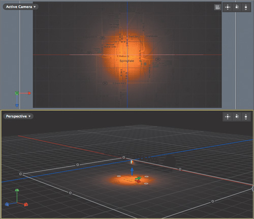
In the Canvas Perspective view, drag up on the top rotate handle 90 degrees to point the light directly down at the map.

Drag the green Y-axis arrow to center the light over the map.
The light would look a lot better with a soft edge.
Click the Color well and select a light orange.
The orange color of the light supports the orange color of the 2 in the logo. It’s looking a bit dim, however.
In the HUD, increase the Intensity setting to about 200%.

That looks good, but now you can see the edges of the map—just barely, but enough to be distracting.
In the Layers tab, select the Map layer. In the Perspective view in the Canvas, hold down Command-Option and drag a corner control handle to scale the map proportionately and around its anchor point until it fills the Active Camera view.
The map looks more interesting with the addition of the light, but the light creates a bit of a problem: The Action News logo is now completely in the dark. This is because once you add a light to a project, the default ambient light, which ordinarily lights the entire project, disappears. You can solve this problem by adding a directional light to illuminate the logo.
In the Layers tab, rename the current light to Spot.

The new light is automatically placed in front of the logo.
In the HUD, change Light Type to Directional.
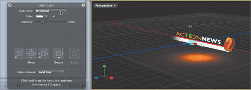
Directional light emits parallel light rays, similar to the sun’s rays, which are almost parallel when they hit the earth. The light has no falloff, so all objects are lit at the same intensity, no matter how far they are from the light.
In the Layers tab, rename the new light to Directional.
Save your work.
With the 3D scene created and with the camera and lights all in position, you can animate the camera and reveal the scene elements.
Motion lets you create animation in two different ways: using traditional keyframing, which allows for precise control; and using behaviors, which create procedural animation by adjusting timing and other parameters. Animating a camera is no exception. You can keyframe its position and rotation, or use one of several camera behaviors that quickly dolly, sweep, and zoom the camera in 3D space. In this exercise, you’ll first animate the camera with behaviors, and then compare those results with keyframing.
The first task is to rotate the camera to reveal the Action News logo. However, just rotating the camera isn’t enough.
In the Layers tab, select the Camera.
In the Perspective view in the Canvas, move the pointer over the circle that shows the red X-axis rotation circle; then drag left to rotate the camera 90 degrees so that it faces the logo. Use the 3D View tools to reframe the view.

Because the camera’s focal plane is aligned with the map graphic below the logo, the camera rotates around the map graphic and ends up pointing below the text, as indicated in the Inset and Active Camera views. So, in addition to rotating the camera, you also need to move it up along its Y-axis to point straight at the logo. You’ll move and rotate it with behaviors.
Press Command-Z to undo the rotation.
In the Library, select Behaviors > Camera. Select the Dolly behavior and watch the preview at the top of the Library.

The Dolly behavior moves the camera backward and forward along its Z-axis.
Drag the Dolly behavior onto the Camera in the Layers tab.

Let’s say that the first camera move will last for 1 second.
In the current frame field, enter 1. (1 period) and press Enter. Press O to trim the behavior to the playhead. Choose Mark > Play Range Out to set a short play range around the behavior. Start playback.

Nothing happens.
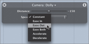
In the HUD, try setting Distance to -150 pixels.
It can be difficult to make small adjustments in the HUD, so try using the Inspector.
In the Behaviors tab of the Inspector, set the Distance value to -150.

The camera now dollies back to its original position, and the focal plane is aligned with the Action News logo.
In the HUD, change Speed to Ease Out to bring the camera to a smooth stop.
To rotate the camera, you’ll use the Sweep behavior.
In the Library, preview the Sweep behavior.

The Sweep behavior rotates the camera around its focal plane. If the camera’s focal plane is touching an object, it will rotate around that object.
Drag the Sweep behavior onto the Camera in the Layers tab.
Stop playback, move the playhead to 1:00, and press O to trim the Sweep behavior’s duration to match the Dolly behavior. Resume playback.
In the HUD, set the End value to 90°.
In the HUD, click the Axis pop-up menu and choose Tilt X. Change the Speed pop-up menu to Ease Out.

The camera now tilts to reveal the logo as it dollies up to center it.
In the Canvas, select the upper Active Camera view to see the animation from the point of view of the camera. Stop playback and save.
Good work. It’s time to animate the camera to push through the logo.
While behaviors are great for creating animation, you’ll sometimes want the flexibility and precision afforded by keyframing. For example, with keyframes you can control precisely how an object slows down and speeds up. While keyframing is covered in depth in Lesson 10, let’s dive in right now and perform some basic keyframing to animate the camera.
You already know how to navigate the camera with the HUD using the 3D View tools, and by dragging the controls directly in the Canvas. But Motion has a special tool called Walk Camera that lets you manipulate the camera in a unique manner that isn’t possible using any other method. You’ll use this tool in conjunction with keyframes to animate the camera straight through the logo.
Move the playhead to 1:00. Choose Mark > Reset Play Range to expand the play range to the full length of the project.
Your goal is to move the camera toward the logo and push all the way through it to the empty space beyond, where you will add more objects.
You have seen that when you rotate the camera, it rotates around its focal plane—almost as if the camera were tied to the object it is pointing at with a piece of string, and it swings around the string.
But sometimes it’s useful to rotate the camera around its own body so that it pivots to look in different directions, just as if you were standing still while holding a camera and turning your head to look in different directions.
In the Layers tab, select the Camera. In the Perspective view, move the pointer over the red, green, and blue arrows; click once, then press Command. When you see the red, green, and blue rings, drag to freely rotate the camera.

Notice how the camera continues to frame the logo as it rotates.
Undo, and then in the Toolbar select the Walk Camera tool.

Click and drag in the Active Camera view to rotate the camera.
Notice that in both views the camera pivots around its own body, and you can point it to look in any direction.
Undo. With the Active Camera view selected, tap the arrow keys to move the camera forward, backward, left, and right. Undo after each move.
Using the arrow keys, you can control the camera movement as you would in a first-person shooter game.
To animate the camera movement with keyframes, you’ll use Record Animation.
Note
Record Animation is detailed in Lesson 10.
At the bottom of the Canvas, click the Record button.
Any changes you make will now be recorded as keyframes.
Press the Down Arrow, then press the Up Arrow to set a keyframe at the current playhead location without changing the camera position.
In the current frame field, enter 2. (2 period), and press Enter to move the playhead to 2:00.
This is the point in time where the camera will come to rest.
Choose Mark > Mark Play Range Out.

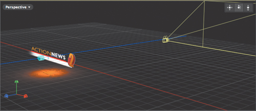
Click in the Active Camera view, and then repeatedly tap the Up Arrow key to move the camera straight through the logo and well beyond it.
Click the Record button to turn off recording.
Play the project.
The camera animates around and through the logo, coming to rest while looking at empty space. You’ll take care of that in a moment. But when the camera passed through the logo, things looked a bit blurry.
Stop playback, and in the mini-Timeline move the playhead to a frame just before the logo passes out of view at about frame 1:14.

The letters of Action News are very close to the camera and look quite blurry. This is a text layer created inside Motion, and it is vector based, so it should be sharp. What’s going on here?
Click the View and Overlay Options menu, and from the Render Quality section choose Best.

The text now looks nice and sharp. By default, the render quality is set to Normal for better playback performance.
Click the View and Overlay Options menu and return the Render Quality setting to Normal. Save your work.
To finish the project, you’ll add a final 3D “set” that includes still images, video, and animated text elements, and then you’ll use a behavior to animate the camera to sweep around the set.
Choose Mark > Go To > Play Range End to move to the play-range Out point at 2:00, where the camera comes to rest.
When you move the playhead here, any elements you import directly into the Canvas will be centered at the current location of the focal plane of the camera.
In the File Browser, locate the Storm Watch file, and drag it to the center of the Active Camera view in the Canvas.

In the Canvas, the new elements appear with a 3D bounding box, and they appear at an angle. In the Layers tab, a new group appears.
Click the disclosure triangle for the Storm Watch group to view its contents.
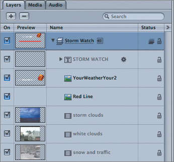
The group contains a text layer, two graphics layers, and three video clips. The text layer and the video layers are dimmed because they don’t exist at the current playhead location.
Press Home to move the playhead to the first frame, and then choose Mark > Move Selected In Point to move the entire group to start at the beginning of the project.

Move the playhead to 3:00, and choose Mark > Mark Play Range Out to set a new play range. Play the play range. The video may “pop” onscreen. You’ll deal with that shortly.
By 3:00, the text has animated on and the video clips are playing. This is the frame where the camera will come to a rest.
In the Layers tab, close the Storm Watch group, and then select it, if necessary.
Press F1 to open the Properties tab of the Inspector. If necessary, click the disclosure triangle to view all the Rotation parameters.

You can see that the group is rotated 45 degrees on the Y-axis, which is why it appears at an angle.
You are now ready to sweep the camera around this group.
This is the location of the previous keyframe where the camera came to a rest. It’s where you’ll start the camera rotation.
In the Layers tab, select the Camera.
Remember, you want to animate the camera, not the Storm Watch group.
In the Toolbar, click the Add Behavior icon and choose Camera > Sweep.

The behavior appears in the Layers tab as Sweep 1.
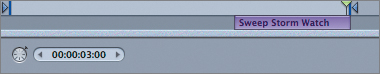
Rename the behavior to Sweep Storm Watch.

Choose Mark > Mark In to trim the behavior’s In point to the playhead.
You don’t want the sweep to start until the camera has come to a rest at 2:00.
Move the playhead to 3:00 and choose Mark > Mark Out.
This is where the camera will stop moving.
In the HUD, drag the End slider until the camera faces the group straight on at about 43 degrees. Set Speed to Ease Out to bring the camera to a gentle stop.

Drag the play-range Out point to about 4 seconds to create some extra room. Click the 3D View Options menu and switch back to a single viewport. If necessary, use the Camera menu to set the view to Active Camera, and press Shift-Z to fit the project to the window. Play the project.
The camera now animates gracefully around and through the first logo, and sweeps around the Storm Watch set, thanks to a combination of behaviors and keyframes. One more tweak will clean things up.

As the project plays, you can see the Storm Watch group in the background while the camera is still showing the initial logo. That’s distracting. You could trim the group or animate its opacity. Instead, you’ll adjust how far the camera is able to see into the distance.
Move the playhead to a frame where the camera has just passed through the logo at about 1:16.
You want the Storm Watch group to start to come into view after this point.
In the Layers tab, select the camera, and then go to the Camera tab of the Inspector.

Decrease the Far Plane value to a point where the Storm Watch group is almost entirely hidden, at about 1200 pixels.

Play the project.
The group doesn’t appear until the camera has just passed the logo.
Congratulations! You have navigated in 3D space using Motion’s 3D overlays, the HUD, and the Inspector. You’ve also used multiple viewports to orient and animate a camera around and through objects in 3D space. And you’ve created the camera animation using both behavior and keyframes. You are well on your way to developing your 3D navigation skills.