16-2 Project 1: Milling Vise
Figure 16-1 shows a milling vise. The subassemblies, detailed drawings, and BOMs are included.
Figure 16-1
Complete the following or as assigned by your instructor.
See Figure 16-1 .
A. An assembly drawing
B. A BOM; include Item Numbers, Part Numbers, Descriptions, and Quantities
See Figure 16-2 .
Figure 16-2
An assembly drawing of base subassembly of the milling vise is shown. Several parts of the base subassembly are numbered. A BOM below the drawing lists the item numbers (that are labeled in the drawing) and their respective part number, description, and quantity. The BOM infers the following data. Item number 1 - BU2012-B, base, 1; Item number 2 - P100-20A, (ACME, base), 1; item number 3 - BU-313, (plate, cover, base), 1; item number 4 - M6 by 1.0 by 16, (screw, slotted cap), 2; item number 5 - PN31 1-lA, (handle, subassembly), 1; item number 6 - M8 by 1.25, (nut, hex), 1; item number 7 - ENG-2, collar, 1; item number 8 - M6 by 1.0 by 10, (set screw-cone), 1.
A. An assembly drawing
B. A BOM
C. Dimensioned drawings of each part that is used in the subassembly
Figure 16-3
The first diagram shows a rectangular object with three 'U-cuts' on the upper and the lower edges. The cuts are made inward. The total height of the object is 120. The object is horizontally separated into three portions, one portion along the middle and the other two along the upper and lower edges. The middle portion is wider than the others. A horizontal center line is drawn through the middle portion. The object is symmetric about the center line. A rectangular block of height 88 is drawn in dashed lines within the outer block. The distance between the left edges of the outer block and the inner block is 16, distance between the center line and the lower edge of the inner block is 44, and the distance between the lower edges of the inner block and the outer block is 15. Another rectangular block of height 36 is drawn in dashed lines, around the middle portion and the distance between them is 2 all around. The distance between the center line and the lower edge of this block is 18. The distance between the left edges of the outer block and this block is 26. Three 'U' cuts are made on the edges at a distance 65 from the left edge. The radius of the cuts is 6.50. The distance between the start and the end of the cuts is 100. Center marks are drawn for the cuts. The distance between the left edge of the outer block and the center of the first cut is 84.50, distance between the left edge and the center of the second cut is 115, distance between the left edge and the center of the third cut is 145.50. The length of the cuts at the bottom is 100. The length of the left section at the bottom is 66. The height of the centerline from the base is 44. The length of the inner section of the object is 88. The dimension of the third portion is 16. The length of the second portion is 38 and the distance of the bottom surface of the second portion from the centerline is 18. The thickness of the edges inside the object is 2 in all places. The reference lines form a rectangular block inside the object. The left section of the reference rectangle is 16 units from the left section of the object. The top of the reference rectangle is 26 units from the left section of the object. The second diagram resembles a rectangular slab with the length 230. The thickness of the bottom section is 10. The cuts of the object are drawn with reference lines and the angle is 114 degrees. The other diagram shows a flat bottom surface that has two small holes and one large hole. The left section has a step cut and a diagonal cut and the top surface has a cut at the center. The right section is symmetric with the left section. The height of the object is 41.44. At the left section, the height of the step cut is 28. The width of the block at the bottom surface is 20 units. At the right section, the height of the step cut is 28. The height of the block is 13 units. The holes are located at a distance of 25 units from the base. The diameter of the smaller holes is labeled M6 times 16 and the diameter of the large hole is 16 units. The distance between the large hole and the small hole is 20 units. The cut at the top section is 5 units deep. The large hole is located at a distance of 60 units from the left section. The third diagram shows a sectional view of the previous diagram. The top left section is highlighted with the step cut, the diagonal cut, and a partial cut of the large hole. The angle of the diagonal cut is 60 degrees. The distance of the large hole from the horizontal surface of the top section is 18 units. The angle at the flat surface of the diagonal cut and the angle at the diagonal region is 32 degrees. The cut is 20 units deep from the left section.
Figure 16-4
An object resembles a bolt of length 293 units. The dimension of the spiral section is labeled "M16 times 4 ACME." A circular cut (labeled 'A') is made and the sectional view is shown besides. The length of the section is 93 units. The thickness at the top section is 10 units. The length of the middle section is 57 units. The dimension at the bottom of the object is labeled M8. The length of the block connecting the middle section and the bottom surface is 12 units. The sectional view (section B-B) of the object is shown below. The diameter of the object is 16 units labeled R5. The length of the inner section is labeled 8 SQ. The square inside the circle is present at a distance of 4 units.
Figure 16-5
An object resembles a hollow cylinder. A hole is present at the top section. At a distance of 2 millimeters from the center, "3210123" is written. The height of the writing is 2 millimeters. The sectional view of the object is shown where the length is 20 units and the height (diameter) is 22 units. The other sectional view of the object is shown. The length of the inner section of the object is 11 units (diameter). The dimension at the center is M6 times 1. The hole is located at a distance of 8.88 units from the left section.
Figure 16-6
An object has two small holes, one at the left section and the other at the right section. A large hole is present at the center at a distance of 20 units from the left section. The distance between the smaller holes is 40 units. The diameter of the smaller holes is 8 units and the diameter of the large hole is 16 units. The sectional view resembles a vertical plate with a thickness of 3 units.
Figure 16-7
A diagram shows the three dimensional view and the parts list of a handle subassembly. The subassembly consists of three parts, rotator, insert, and cover. The insert is peen into the cover via the rotator hole during assembly. The parts are labeled, 1 to 3. The parts lists table shows the item number, part number, description, and quantity. The table can be read row-wise as follows: 1, BU4-1, rotator of the handle, 1; 2, BU4-2, insert of the handle, 1; 3, BU4-3, cover of the handle, 1.
Figure 16-8
A diagram illustrates the orthographic views of the rotator in a handle. The front and side views of the rotator are shown. The right end, middle portion, and left end of the rotator are rounded of to a radius of 9. A circular hole of diameter 10.50 is cut on one end of the rotator where the insert is peen upon assembly. A square hole with sides measuring 8 are cut in the middle portion of the rotator. The distance between a side of the square and the center line of the square hole is 4. The distance between the end centers and the center point of the rotator is 34. The total breadth of the rotator in the slot portion is 10. The top edge of the rotator is at a height of 5 from the horizontal center line. The thickness of the rotator is 10. The hidden edges of the holes in the rotator are represented in dashed lines on the side view. A note reads, all the fillets equal 2R.
Figure 16-9
A figure shows a three-dimensional model and two orthogonal views of the handle insert. The three-dimensional model shows a cylindrical body attached to a cylindrical head. The side view shows a horizontal bar attached to a small rectangle. The length of the entire body is 63. The breadth of the small rectangle is 15. Both are symmetric about a horizontal axis. The front view resembles two concentric circles, the diameter of the outer circle is 17 and the inner circle is 10.
Figure 16-10
A figure shows the dimension details of the cover of the handle. A three-dimensional view shows the outline of the cover as a cylindrical body with the radius increasing from one end to the other, such that, one end is wider than the other. A side view of the cover is shown, where the length of the cover is marked 50. A cross-section A-A is taken lengthwise. The cross-section reveals the fitting of the handle insert inside the handle cover. The diameter of the cover at the wider end is 22 and the diameter of the cover at the narrower end is 16. The insert space diameters are: at the wider end is 18 and at the narrower end is 10.
Note
Standard parts do not need drawings, but require manufacturer’s part numbers listed in the BOM.
See Figure 16-11 .
Figure 16-11
A figure presents two different models of the middle subassembly of the milling vise, along with BOM. The middle subassembly shape as depicted in the three-dimensional model is as follows. A rectangular frame is at the bottom over which is a H-shaped frame. A cylindrical bar, covered with a coiled layer passes through the gap of the two arms of the H-shaped frame, through the center of the bar connecting the two arms. From this view, one of the arms of H-frame has three screws, equidistant from one another. The coiled cylindrical bar is screwed to a triangular plate, which in turn, is connected to the handle subassembly. The alternative view given below shows the bottom of the rectangular frame that acts as the base of the middle assembly. It has a small cylindrical bottom support at the center. It also shows the shape of the connection between the post and the handle subassembly, which resembles an L-shape. The parts of the middle subassembly are numbered as follows. The arms of the H-frame are numbered 1. The triangular plate is numbered 3. The part that connects the handle to the plate is numbered 4. The rectangular base is numbered 11. The post connected to the handle is numbered 7, through a part numbered 6. A few screws are numbered 10, while a few are numbered 8. The BOM table is as follows. The table includes details: item number, part number, description, and quantity. The data is as follows. 1, S51-2A, Support middle. 2, P200-24, Post, Acme, middle. 3, WIT-130, Plate end. 4, ENG-2, Collar. 5, PN311-1A, Handle subassembly. 6, M8 cross 1.25, Nut, hex. 7, P155B, Post middle. 8, M6 cross 1.0 cross 25, Screw pan. 9, SP-33, Bar spacer. 10, M6 cross 1.0 cross 16, Set screw, socket. The item number 8 (screw)'s quantity is 8 and the item number 9 (bar)'s quantity is 2. The rest are 1 each.
A. An assembly drawing
B. A BOM
C. Dimensioned drawings of each part that is used in the Subassembly
Figure 16-12A and 16-12B Middle Subassembly
Figure 16-12
A diagrammatic representation of the middle subassembly. A three-dimensional model of the middle subassembly is given, which is constituted of a rectangular base. The base has dovetail shaped bottom supports. Further, a H-shaped frame is placed over the rectangular frame, whose ends are also dovetail shaped. The fillet locations are specified in the model. The top view of the middle assembly portrays the model as follows. A rectangular frame is at the bottom, above which a H-shaped frame is placed, such that, the arms of the H are perpendicular to the lengths of the rectangular frame.
Note that Figure 16-12A shows a dimensioned drawing of the Support, Middle, but does not include any fillets. Fillets were omitted for clarity. Figure 16-12B is a 3D of the Support, Middle, that shows the fillets. Use the fillets shown in Figure 16-12B as a guide to applying fillets.
Figure 16-13
In the sketch of the acme post, a stepped rectangular section is shown at the bottom of the post. Above this section, M16 by 4 acme threads is shown in a vertical section. The total length of the post is 231. An enlarged view of the lower section 'A' is shown. the total length of this section is 86. It consists of three rectangular sections of different widths. The topmost section just below the threads is of length 10. The next section is of length 45. In the lower section, a small rectangular block of length 12 is shown at the top. Here, a cutting plane line B-B is drawn. The dimension M8 is marked in this section. The bottom of this section has a 0.50 by 45 degrees chamfer. The section B-B, of scale 1 is to 1 is shown. In this section, two concentric circles are shown. The outer circle is of diameter 16 and the inner circle is of radius 5. A square is inscribed within this circle and the length of the sides for this square is 8.
Figure 16-14
An end plate is triangular with three holes at the three corners. The corners are curved. The radius of the two curved ends at the top is 8 and the radius of the curved end at the bottom is 12. The diameter of the hole near the bottom end is 12. The diameter of the two holes at the top is 8. Here, the distance between the centerline of the holes at the left and right is 32. The distance between the centerlines of the hole at the top and the bottom is 12 vertically and 16 horizontally. In the front view, the plate is rectangular of width 4.
Figure 16-15
In the top view, the middle post is circular of diameter 27 with a hole at the center. A spring is coiled within the circular section. A front view of the middle post is also shown. It consists of a rectangular section of height 28. A vertical and horizontal reference line is drawn through the center of this section. Spring (M1 6 by 4 ACME) is shown within this rectangular section and the rectangular section has a curved dent on either side. On top of this section, another rectangular section of height 12 is shown. The diameter tolerance range for this section is 16 to 16.012 (K6). Two ends of this section are chamfered by an angle of 45 degrees.
Figure 16-16
A spacer bar is a rectangular bar of length 142 and width 10. It consists of three holes, which are equidistance from each other. That is, the distance between the holes is 55. The center hole is at the center of the rectangular bar. That is, the distance from the centerline of the hole at the center to one end of the rectangular bar is 71. The thickness of the bar is 2. The diameter and depth of the holes are 4 and 1 respectively. The fillet radius is 1 (3 placers).
A. An assembly drawing
B. A BOM
C. Dimensioned drawings of each part that is used in the Subassembly
Note
Standard parts do not need drawings, but require manufacturer’s part numbers listed in the BOM.
Dimensioned and toleranced drawings of the parts that make up the base subassembly are as follows:
Figure 16-17A and Figure 16-17B Top Subassembly
Figure 16-17
The object consists of top support. The top support labeled 1 has a rectangular base with a vertical extension at both ends. A guide post labeled 2 is circular and is attached to one end of the top support. A movable jaw labeled 3 is a vertical block placed over the top support. One side of the movable jaw is rectangular with two holes. An acme post is labeled 4. It is cylindrical with threads winded over it. One end of the post is fixed to the movable jaw. The other end of the post is fixed to a handle, which is labeled 5. The acme post is attached to the handle through a set screw. A jaw plate labeled 6 is parallel to the movable jaw. Two rivets are fixed to the vertical section of the top support. A parts list table is shown. The item number, part number, description, and quantity listed in the table are as follows: 1, S50-1, top support, and 1; 2, P200-16, guide post, and 1; 3, MJ100-2A, movable jaw, and 1; 4, M16 by 4, top acme post, and 1; 5, M407-A, top handle, and 1; 6, PT100, jaw plate, and 2; 7, diameter 3.5 by 16, 3.5 by16 rivet, and 1; 8, M6 by 1 by 8, set screw-dog, and 1; 10, M6 by 1 by 6, set screw cup, and 1.
Figure 16-18
The front view, top view, bottom view, and side view of the top support are presented. In the front view and bottom view, the object consists of a horizontal section, which is rectangular. The left end of the horizontal section consists of a rectangular block at the top and an M6 by 1 tapped hole at the bottom. This rectangular bock is of width 30 and consists of M 16 by 4 acme thread. The right end of the horizontal section consists of a block of width 30 and height 36 on top of it. This extension has a ramp at the right end and a cut of depth 1 at the right end. The horizontal section consists of a small cut of depth 3 at the left end, near the rectangular block. The horizontal section also consists of a small cut of depth 2 in the right end near the extension. In the top view, the support is a rectangular frame of length 200 and width 104. The corners at the left end are curved and here the radius is 15. The distance between the outer and inner wall on the right side is 30. Two vertical lines are drawn at a distance of 38 from the left and right ends. A horizontal cutting plane line A-A is drawn through the center of the object. In the left side view, the object consists of a rectangular section. The base of the rectangular section consists of a dome-shaped projection, which is of radius 14. Within this projection, two holes are shown one below the other. The distance between the centerlines of these two holes is 26. The hole at the bottom is of diameter 16. Two small tapped holes M6 by 1 are shown on either side of this hole. The distance between the centerlines of these holes is 26. Two holes of diameter 7 are shown on either side of the dome-shaped projection. The distance between the centerlines of these holes is 60. The distance between the centerline of this hole and one side of the rectangular section is 22. The center part of the rectangular section has a downward extension at the bottom. This extension is of height 10 and has a ramp on both sides.
Figure 16-19
An acme post consists of a vertical section winded with acme threads. The dimension of the thread is given as M16 by 4 acme threads. The overall length of the post is 190. Detailed view 'A' and B of the top and bottom sections are shown, respectively. Detail 'A': Scale 2 is to 1. The top section of the post is U-shaped. The base of this section is of diameter 16. The two vertical blocks of the U-shaped section is 7 units apart. The total height of this section is 24 and the height of the vertical blocks alone is 16. A hole of diameter 4 is on both vertical blocks. The distance between the centerlines of these holes and the top edge is 6. The top corners of the U-shaped section are chamfered and the angle is 0.75 by 45 degrees at both ends. Detail B: Scale 2 is to 1. The bottom of the acme thread is attached to a rectangular section of length 14 and diameter 10. Another rectangular section is attached below it, which is of length 6 and diameter 7. Again a rectangular section of diameter 10 is attached below. The corners at the bottom are chamfered. The total length of all three sections is 26.
Figure 16-20
Figure 16-21A and Figure 16-21B Jaw, Movable
Figure 16-21
An isometric view, front view, side view, and top view of a movable jaw are presented. In the top view, the movable jaw is rectangular of length 100 and width 30. A horizontal line is drawn at a distance of 13 from the top edge. Two vertical lines are drawn below the horizontal line, at a distance of 8 from the two ends. An M6 by 1 hole is shown at the center. In the front view, a section in the shape of a rounded rectangle is attached vertically to a rectangular section at the center. The ends of the rounded rectangle are of radius 14. The rounded rectangle consists of two holes, one below the other. The hole at the top is of diameter 11 and depth 20.97. The distance between the centerline of this hole and the base of the rectangle is 21. The hole at the bottom is of diameter 16. The distance between the centerline of these holes and the two sides of the rectangular section is 50. Two small rectangular cuts on the bottom of the rectangular section are shown on either side of the rounded rectangle. The length and depth of these cuts are 50 and 5, respectively. Two holes of diameter 7, on either side of the rounded rectangle, is at a distance of 26 from the base of the rectangular section. The distance between the centerlines of these holes is 60. Note that all fillets have been removed for clarity. In the isometric view, the movable jaw consists of an L-shaped plate. A section attached to it is in the shape of a rounded rectangle. This section is vertically attached and consists of two holes. The L-shaped plate consists of two holes on either side of this section.
Note that Figure 16-21A shows a dimensioned drawing of the Jaw, Movable, but does not include any fillets. Fillets were omitted for clarity. Figure 16-21B is a 3D of the Jaw, Movable, that shows the fillets. Use the fillets shown in Figure 16-21B as a guide to applying fillets.
The Tenon Jig has four main subassemblies: Clamping, Vertical, Base Plate, and Guide Plate. There are other parts that are used in the final assembly. This is intended to be a group project, but could be done by one person. Complete the following assignments:
A. Draw the Clamping Subassembly.
C. Draw the Base Plate Subassembly.
D. Draw the Guide Plate Subassembly.
E. Create an Assembly drawing of the Tenon Jig.
Figure 16-22
The front view and side view of the handle are shown. The handle consists of a long rectangular section. The top end of this section is attached to a thin rectangle of length 16 and width 5. In this section, a hole of diameter 4 is shown. The distance between the centerline of the hole and the top end is 8. The distance between the centerline of the hole and the sides of the section is 7. The bottom corners are chamfered by an angle of 1 by 45 degrees at both ends. In the top view, a rectangular block of width 5 is inscribed in a circle of diameter 14.
Figure 16-23
The front and side views of a jaw plate are shown. The jaw plate is rectangular of length 100, width 26, and thickness 5. Two tapped holes M6 by 1 are shown on this rectangular plate. The distance between the end centers is 60. The distance from the centerline of a hole to one side of the plate is 20.
Figure 16-24A
Figure 16-24B
Figure 16-24C
A schematic representation of the Tenon Jig is shown. The following parts are shown in the figure. The base sub-assembly is labeled 1. The adjuster sub-assembly is labeled 3. The drilled forged hexagon socket head cap screw is labeled 6. The slotted head machine screw is labeled 7.
Figure 16-24D
A parts list table is presented for the Tenon Jig. The item, part number, description, material, and quantity listed in the table are as follows: 1, SA-1, base sub-assembly, and 1; 2, SA-2, vertical sub-assembly, and 1; 3, SA-3, adjuster sub-assembly, and 1; 4, SA-4, guide sub-assembly, and 1; 5, SA-5, clamp sub-assembly, and 1; 6, M10 by 1.5 by25, drilled forged hexagon socket head cap screw, mild steel, and 2; 7, SA-6B, slotted head machine screw, mild steel, and 2.
Figure 16-24E
The front view and side view of a slotted head machine screw are shown. In the front view, the rectangular head of the screw is of depth 3. A rectangular block attached to the head is of length 9. Below this block, threads are shown on a rectangular block of length 12. The dimension of the thread is M6 by 1. The ends of the block are chamfered by an angle of 0.5 by 45 degrees. The head of the screw is represented by two concentric circles of diameter 12 and 8. A rectangular slot along the center of the head is of width 2.
Figure 16-25
An isometric view and an exploded view of an object are shown. The object consists of a C-Bracket. The C-bracket is in the shape of inverted J. A slider in the shape of a rounded rectangle is fixed to the C-bracket through a pin. The top end of the slider is fixed to the C-bracket while in the lower end, a threaded post is assembled into it. One end of the threaded post, which is near to the C-bracket is fixed to a holder. The other end of the threaded post is attached to a pivot handle. The pivoted handle is fixed vertically and the top end of the handle is attached to a handle post. A cylindrical section consists of a thumbscrew at one end and a plain washer on the other end. This is assembled into the slider through the washer from the rear end of the slider. A parts list table is presented. The item number, part number, description, material, and quantity listed in the table for each part is as follows: 1, BU-121, C-Bracket, casting, and 1; 2, BU-122, pin, steel, and 1; 3, BU-123, threaded post, steel, and 1; 4, BU-124, thumb screw, steel, and 1; 5, 10 by 24 by 2, plain washer, steel, and 1; 6, BU-125, slider, casting, and 1; 7, BU-126, holder, steel, and 1; 8, BU-127, pivot handle, casting, and 1; 9, BU-128, handle post, steel, and 1; 10, M6 by 6, set screw, socket head, flat point, steel, and 1.
Figure 16-26
The front view and the side view of a C-bracket are shown. In the front view, the C-bracket is in the shape of inverted J. That is, a horizontal section of length 163 is attached to a long vertical section in the left and a short vertical section of length 84 and width 26 in the right. All these sections are rectangular. The left vertical section is of width 24. Near to the base, one side of this vertical section tapers. The width at the bottom of this vertical section is 14. A rectangular slot of length 128 and width 28 is present in the horizontal section. The distance between the slot and the horizontal section at the top is 6. The distance between the slot and the horizontal section on the sides is 12. The vertical section in the left consists of two holes of depth 14. Also, two holes are shown in the right vertical section. In the side view, the C-bracket is a vertical block that is rectangular. The total length of the block is 208. Four holes are shown in the vertical block. The two holes at the bottom show the diameter 12 for the holes and 18 for the bosses. The distance between these two holes is 54. The distance between the first and the third hole is 132. The distance between the first and second hole is 62. The dimension of the second hole is M8 by 1.25 and is of radius 12. The distance between the centerline of the holes and the sides of the block is 12. The distance between the first hole and the top of the block is 10.
Figure 16-27
The front view and side view of a pin are shown. In the front view, the pin is rectangular of length 50. In the side view, the pin is in the shape of a circular ring which is open at one point. For the pin, the radius of the outer wall is 6 and the radius of the inner wall is 4. The length of the opening in the ring-shaped pin is 3.
Figure 16-28
The front view and side view of a threaded post are shown. In the front view, the post shows a rectangular block of length 142 with a break in between. The diameter of this rectangular block is 10.5. This block consists of M12 by 1.75 thread. A rectangular extension of length 10 units is on either side. The diameter of the rectangular extension in the left end is 8 and the diameter of the rectangular extension in the right end is 10. In the side view, the post is circular.
Figure 16-29
The front view and side view of a thumbscrew are shown. The head of the screw is of height 8. The corners of the cap consist of a 1 by 45 degrees chamfer at 3 places. A thin rectangular block of width 3 is fixed to the bottom side of the cap. Then a long rectangular block represents the threaded region of the screw. The total length of the screw is 71. The side view of the screw shows the circular head. The outer circle is of diameter 30 and the inner circle is of diameter 20. The circular hole at the center is of dimension M8 by 1.25.
Figure 16-30
The top view and front view of a slider are shown. In the top view, the slider is in the shape of a rounded rectangle. The distance between the end centers of the slider is 137. The radius of the corners is 12.5. It consists of a slot in the shape of a rounded rectangle. The distance between the end centers in this slot is 106 and the radius of the corners is 6.5. It also contains an M12 by 1.75 hole at the right end. In the front view, the slider is rectangular of width 34.
Figure 16-31
The front view and side view of a holder are shown. In the front view, the holder is T-shaped. A vertical block of width 5 is attached to a horizontal block at the center. The length of the horizontal block is 17. A thin section at the end of the horizontal block is of width 1. The total length of the holder is 24. The vertical block has a 0.5 by 45 degrees chamfer at the ends. The horizontal block has a fillet radius 5 near the vertical block. In the side view, the holder is circular. The diameter of the outer circle is 40 and the diameter of the inner circle is 16. The diameter of the hole is 10.3 and the diameter of the bottom drill is 11.5.
Figure 16-32
The front view and top view of a handle are shown. A conical section, which is of width 12 near the left end becomes wider towards the right end. The end tapers from diameter 8 to 14 over 64. The left end and the right end are circular, such that the radius of the right circular end is greater. Also, the center of the handle is circular of radius 8. A hole in the circular section at the left end is of diameter 5. A hole in the circular section at the center is of diameter 9 and dimension M6 by 1. The distance between the vertical centerlines of the circular sections is 32. In the side view, the handle is circular. The diameter of the circle is 2 and the hole is of diameter 16. All chamfers radius equals 0.5.
Figure 16-33
The front view and side view of a handle post are shown. A section of the handle post is in the shape of a truncated cone of length 45. The left end of this section has a 1.6 by 4.9 chamfer. The right end of this section has a thin rectangular extension of length 12. The total length is 57. The side view of the handle post resembles concentric circles. The diameter of the outer circle is 15.8 and the diameter of the inner circle is 12. The range of the diameter for the hole at the center is 4.992 to 5.
Figure 16-34
Two three-dimensional views of an object are shown. It consists of a vertical casting which is rectangular. A rectangular section within it consists of four holes at the corners and a cylindrical extension at the center. This extension also consists of a hole. The remaining section, which is also rectangular consists of a cylindrical extension with a hole. A stud is fixed in this hole. One side of the rectangular section is attached to a triangular section. This triangular section is in turn attached to a flanged bracket. The flange bracket is L-shaped and consists of two holes on one side and a slot on the other side. A lever is assembled into the triangular section and the L-shaped bracket.
Figure 16-35
The exploded view of the vertical subassembly component in the Tenon Jig device is shown with its parts labeled. The details of the parts are tabulated. The tabulation presents the data in the order of Item number, part number, description, material, and quantity. The data inferred from the table is as follows: For item 1, BU-132, Bracket, Flange, Steel, 1; for 2, BU-131, Casting, Vertical, Steel, 1; for BU-133, Lever sub-assembly, material is not specified, 1; for 6 times 18 times 1, Washer, Steel, 1; for M6, Nut, SQ, Steel, 1; for M5 times 24, Hex Socket Set Screw, Flat point, Steel, 1; for M5, Nut, Hex, Steel, 1; for M6 times 24, Stud, Steel, and 1.
Figure 16-36
The orthographic views of a bracket or flange are shown. The top view shows a rectangular strip that is divided into three sections through two narrow slits in the left side of the strip. The length of the rectangular strip is 11.0. The length of the strip between the slits is 3.0 and that of the strip on the left side is 27.0. The strip on the right side of the slit contains two identical holes of diameter 6.00 on either side. The distance between the two centers of the two holes is 45.0. The strip in the middle is cut off at a distance of 13.0 from the top of the strip. The side view of the strip shows a rectangular strip with two identical holes of diameter 5.00 on either side. Two small narrow slits are present at the bottom portion of the rectangular strip. A small square strip is attached between the slits and also contains a hole in the middle. The width of the rectangular strip is 3.00 and the distance of the center of the hole from the outer edge of the strip is 18.0. The distance between the center of the hole and the left end of the strip is 20.0. The third figure depicting the side view shows an L-shapes strip. The height of the strip is 30.0 while the base length of the strip is 20.0. A narrow strip is attached at the middle of the base in the L-shaped strip. The length of the attached strip is 12.0. The width of the L-shaped strip is 2.00 sheet metal thickness.
Figure 16-37A
Figure 16-37B
The orthographic views of the casting vertical component in Tenon Jig device are shown. The top view is labeled as "A", and the two side views are labeled as B. In the top view, the triangular clamp that is attached to the right side of the rectangle is encircled. The dimensions of the figure are not specified.
Figure 16-37C
The top view of the casting vertical component in the Tenon Jig device is shown. The component is rectangular and consists of two equal sections wherein the section on the top is larger in shape. The larger section contains four small rectangular chambers on the four sides. Each chamber contains a hole of radius 10.0. A triangular clamp is attached to the right top corner of the square. The smaller section contains two inverted U-shaped slits on either side. A small hole of diameter 16 is located in the middle between the two slits. A note for the figure reads "All fillets and rounds R equals 1.0 unless otherwise stated."
Figure 16-37D
The top view of the casting vertical component in the Tenon Jig device is shown with its dimensions. The component is rectangular and consists of two equal sections wherein the section on the top is larger in shape. The larger section contains four small rectangular chambers of length 35.0 and breadth 27.0 in the four corners. Each chamber contains a hole of radius 10.0. A triangular clamp is attached to the right top corner of the square. The breadth of each chamber attached to the corner is 18.0. The distance between the edge of the triangular clamp and the edge of the rectangle is 27.0. The smaller section contains two inverted U-shaped slits on either side. A small hole of diameter 16 is located in the middle between the two slits. The U-shaped slit contains a semicircular top. The distance between the cylindrical parts in the slit is 21.0. A narrow slit is present on the right bottom end of the rectangular shape. The distance from the base of the rectangle till the bottom and upper end of the slit is 55.0 and 59.0 respectively.
Figure 16-37E
The triangular clamp in the casting vertical component of the milling vise device is shown. The triangular portion contains two slits. The first slit is cylindrical with rounded corners while the second slit is conical in shape. The clamp is of radius 51.0 and the radius of the cylindrical shape is 60.0. It lies at an angle of 45.2 degrees. The radius of the triangular slit is 2.0. A small hole is present in the right end of the triangle and its radius is 4.5. The base of the triangle is of length 5.2. A small runout is present nearby the hole.
Figure 16-37F
A u-shaped attachment is present along the middle of the clamp. A hole is present on the right side of the attachment. The distance between the center of the hole and the upper edge of the clamp is 76.0. The distance between the center of the hole and the outer edge of the slit is 10.0. A concentric hole is present at the bottom edge of the clamp. The outer and inner diameter of the hole is 13.0 and 9.0 respectively.
Figure 16-37G
The front view of the triangular clamp in the casting vertical component of the Tenon Jig device is shown. The figure shows a horizontally positioned rectangle that is sectioned into three portions by means of two three slots. The height of the slot is 23.0 while the height of the second clamp is 5.0. The width of the clamp is 25.0 while the width of the three slots is 8.0.
Figure 16-37H
The right side view of the triangular clamp in the casting vertical component of the Tenon jig device is shown. The figure shows a vertically positioned rectangle that contains a U-shaped slit with a hole that protrudes from the middle in the left side. The width of the clamp is 23.0. The clamp contains a concentric hole at its base.
Figure 16-38A
The exploded view of the lever subassembly component in Tenon jig device is shown and its parts are labeled. The details of the parts are tabulated in the table for Bill of materials. The data is presented in the order of Item number, part number, description, material, and quantity. The data inferred from the table is as follows: for LV-141, lever, steel, 1; for LV-142, post, threaded, steel, 1; for LV-143, pin, lever, steel, 1; for LV-144, screw, spring, steel, 1; for 6 times 16 times 1, plain washer, steel, 1; for M6 times 14, square nut, steel, 1.
Figure 16-38B
The exploded view of the lever subassembly component in Tenon jig device is shown and its parts are labeled. The details of the parts are tabulated in the table for Bill of materials. The data is presented in the order of Item number, part number, description, material, and quantity. The data inferred from the table is as follows: for LV-141, lever, steel, 1; for LV-142, post, threaded, steel, 1; for LV-143, pin, lever, steel, 1; for LV-144, screw, spring, steel, 1; for 6 times 16 times 1, plain washer, steel, 1; for M6 times 14, square nut, steel, 1.
Figure 16-38C
The orthographic views of the post threaded part in the lever subassembly. The first figure depicting the top view shows a hexagon base that contains a vertically positioned cylinder attached to it. The height of the hexagon is marked as 8.0. The cylinder contains a hole at the middle of diameter 6.00. The second figure depicts the side view of the post threaded part. The figure resembles a cylindrical chamber attached to the right side of a rectangle. The length of the rectangle is 15.0 and the total length of the structure is 40.0. The dimensions of the cylindrical chamber are marked as 0.50 times 45 degrees. The third figure depicts the front view of the post threaded part. The figure resembles a hexagon that contains a concentric circle of two rings at the middle. The radius of the concentric circle is marked as 0.5 for all the rounds.
Figure 16-38D
The orthographic views of the pin lever part in the lever subassembly are shown. The first figure depicting the top view shows a circular base that contains a cross overlapping a small circle at its center. The diameter of the circle is 7.0 and the width of the cross is 1.0. The length of the cross is 2.0. The second figure depicts the side view of the pin lever subassembly. The figure resembles a vertically positioned rectangle attached to a rotating shaft at its right side. A square element at the middle moves over the rotating shaft. The rotating shaft is of diameter 3.00. The length of the whole structure is 13.0. The third figure depicts the front view of the pin lever subassembly. The figure resembles a circular base that contains a concentric circle of two rings at the center. The diameter of the concentric circle is 3.5 and the dimension of the innermost concentric circle is marked as M4 times 0.4.
Figure 16-38E
The orthographic views of the screw and spring part in the lever subassembly are shown. The top view shows a spring of four coils. The side view resembles a waveform. The front view resembles a concentric circle. A note beside reads: Spring, 3.95 inside diameter, 0.25 wire diameter, 2.0 pitch, 4 coils, and flat ends.
Figure 16-39A
Figure 16-39B
Figure 16-39C
An exploded view of the base subassembly in Tenon Jig device is shown and its parts are labeled. The plate structure at the base is labeled as 1, the handle attached to the top corner is labeled as 2, the knob structure is labeled as 3, the conical clip structure at the base is labeled as 4, the screw at the base is labeled as 5, cylindrical shaft at the left end is labeled as 6, spring is labeled as 7, a thin cylindrical pipe is labeled as 8, and a hexagonal nut is labeled as 9.
Figure 16-39D
The tabulation lists the parts of the base subassembly in Tenon jig device. The data is presented in the order of an item, part number, description, material, and quantity. The data inferred from the table is as follows: for BU-306-A, plate, base, cast steel, 1; for P53-A2, post, handle, large, steel, 2; for H5-21, large knob sub-assembly, material is not specified, 1; for BU202, clip, base, steel, 1; for M4 times 0.7 times 10, Cross recessed pan head machine screw, steel, 2; for P23 - 402, post, release, steel, 1; for BU - 003, spring, piano wire, 1; for M5 times 45, stud, steel, 1; for M5, hex nut, steel, and 1.
Figure 16-40A
Figure 16-40B
Figure 16-40C
Figure 16-40D
In the figure, the diagrammatic representation of the base of tenon jig resembles a square shaped-frame with a rectangular frame placed above it. The bottom left of the square shaped frame is round. The top left of the rectangle has a slight outward protrusion. The length of the rectangle is smaller than the length of the square. Further, two holes are along the left edge of the square and two thin protrusions are drawn from the right edge of the square. Another hole is present at the slight outward protrusion of the rectangle. The center is marked with two concentric, round-edged rectangles. Two cross-sectional planes are considered: A-A and B-B. View B-B scale 1 is to 1 gives out the following dimensions. The radius of one of the holes is 10.00 while the other is M 5 times 0.8. The bottom width is 35.0. The width at the top is 25.0. The depth is 10.00. Several notches are along the left-most edge of the cross-section, of varying depth 1.0 and 2.0. The bigger hole is at a distance of 103.00 from the base. The difference in width due to the inward indent on the right side, at the top and the bottom are 10.00 each. Section A-A scale 1 is to 1 provides the following information. The thickness of the runout is 5.0. All boss radii equal the boss height. The difference in thickness due to inward indent at the top is 10.0. The dimensions of the protrusions are as follows. The width of each protrusion is 36.0. The radius of the hole at the end of the protrusion is M6 times 1 (16.00 - 2 holes); (16.00 - 2 places). The distance between the hole and the end of the protrusion is 21.00. It is at a height of 13.50 from the base of the protrusion.
Figure 16-40E
In the figure, the diagrammatic representation of the base of tenon jig resembles a square shaped-frame with a rectangular frame placed above it. The bottom left of the square shaped frame is round. The top left of the rectangle has a slight outward protrusion. The length of the rectangle is smaller than the length of the square. Further, two holes are along the left edge of the square and two thin protrusions are drawn from the right edge of the square. Another hole is present at the slight outward protrusion of the rectangle. The center is marked with two concentric, round-edged rectangles. The dimensions are as follows. The radius of the inner round-edged rectangle is 5.00. The radius of the hole at the bottom left of the square frame is M10 times 1.5. The radius of the round-edge of the bottom left of the square frame is R20.00. Two holes are present at the bottom right of the frame and they are at a distance of 25.00 apart from one another. The radius is M4 times 0.7. The holes are placed at a distance of 10.00 from the outer edge. The center of the hole at the bottom left is at a distance of 115.00 from the right edge. The thickness of the outer-wall of the frame is 7.00. The distance between the two protrusions is 87.00. The thickness of each protrusion is 14.00. The length of the square frame is 130.00. The radius of the hole on the top left is 14.00. The difference in length between the square and the rectangle is 15.00. The thickness of the outer wall of the rectangular section is 6.00 at the top and bottom and on the sides is 15.00.
Figure 16-40F
In the figure, the diagrammatic representation of the base of tenon jig from the bottom view resembles the mirror image of the base from the top view. In this case, the protrusions are on the left. The length of the entire frame (the square and the rectangular regions) is 168.00. The distance between the two protrusions is 129.00. The bottom protrusion is at a distance of 28.00 from the base. The runout is at a distance of 42.00 from its nearest side. The region of the square holding the hole is of width 26.00, symmetric about the center of the hole. The rounded edges of the rectangles at the center of the square frame is of radius 14.00. The distance between the centers of the rounded edges is 63.00. The distance between the center of the rounded edges and the base is 66.44. The length of the base is 135.00.
Figure 16-40G
In the figure, the view B-B shows several dimensional factors of the tenon jig. The radius of one of the holes is 10.00 while the other is M 5 times 0.8. The bottom width is 35.0. The width at the top is 25.0. The depth is 10.00. Several notches are along the left-most edge of the cross-section, of varying depth 1.0 and 2.0. The bigger hole is at a distance of 103.00 from the base. The difference in width due to the inward indent on the right side, at the top and the bottom are 10.00 each.
Figure 16-40H
The dimensions of the protrusions are as follows. The width of each protrusion at the base's end is 36.0. The radius of the hole at the end of the protrusion is M6 times 1 (16.00 - 2 holes); (16.00 - 2 places). The distance between the hole and the end of the protrusion is 21.00. The distance between the base and the center of the hole is 15.00. The difference in height from the top of the protrusion and the hole's placement is 10.00.
Figure 16-40I
Section A-A scale 1 is to 1 provides the following information. The thickness of the runout is 5.0. All boss radii equal the boss height. The difference in thickness due to inward indent at the top is 10. Another runout is denoted at the top, whose thickness is 5.00.
Figure 16-41
The dimensions of the post handle are shown in a diagram. Two orthogonal projections are presented. The handle has a cylindrical shape with a small cylindrical protrusion at one of its ends. The front view of the model resembles concentric circles. The ends of the cylindrical body of the handle are chamfered. The chamfering at the end where the protrusion attaches is done just before the attachment. Here the chamfer dimension is 2 times 45. On the other end, the chamfer dimension is 2 times 8. The length of the entire handle is 87.00. The length of the protrusion is 14.00. The loose end of the cylindrical protrusion is also chamfered and the dimension is 1 times 45. The cylindrical protrusion is labeled M10. The radius of the larger cylindrical part is marked 20.0.
Figure 16-42A
Figure 16-42B
A drawing of the knob subassembly shows the three parts: handle, washer, and stud, numbered 1, 2, and 3 respectively. The handle is of a thick star-shaped object with a small protrusion at the back and a hole at the front. The washer is a circular ring with a hole at the center. The stud has a thin cylindrical body. A table below provides details about the same under five column headers: item number, part number, description, material, and quantity. The data is as follows. 1, HA-102, Large Handle, Plastic, and quantity is 1. 2, 9 times 24 times 2, Washer, SAE1020, and quantity is 1. 3, M8 times 1.25 times 52, Stud, Steel, and quantity is 1.
Figure 16-42C
In the figure, the front and side views of the washer are given. The front view portrays the washer as two concentric circles. The diameter of the outer circle is 24.0 and the diameter of the inner circle is 9.0. The thickness of the washer is mentioned in the side view, which is 2.0.
Figure 16-42D
A figure shows the front and side view of the large handle. The front view portrays the large handle as a five-pointed star with the edges bent inward. Also, the vertices of the star-shaped body have rounded, soft edges. The star-shaped body is indicated to have a hole at the center, drawn as two concentric circles. The diameter of the inner circle is marked M8 times 1.25. The diameter of the outer circle is marked 16.0. The thickness of the outer wall of the body is 2.3 all around. The radius of each corner of the body (the vertices of the star) is 3.0. The side view of the large handle portrays it has a vertical bar attached to a small rectangle in the middle region along its left. The width of the entire model is 23.0. The width of the vertical bar region is 10.0. A hidden region at the center is marked of height 12.0. The hidden region at the center of the rectangular portion is marked 12.0. The gap between the hidden region at the center of the vertical bar and its right-side edge is 1.0. Two other dimensions are marked based on the hidden region inside the rectangular area.
Figure 16-42E
In the figure, the outline of the large handle (front view) is drawn over a grid sheet, with the center of the model aligning with the center of the origin of the sheet. The model is drawn as a five-pointed star, where the vertices (corners) are rounded; the edges are bent inward. A circle is drawn inside the model with the center same as the model. The diameter of this circle is 12. Another circle is drawn passing through the model with diameter 36. Further, a pentagon is drawn inside the circle, with each of its vertices touching the circle, the falling inside the model, just below the rounded corners of the model. The radius of each rounded corner is 3.
Figure 16-43
A figure presents the top, front, and side view of the clip (base) part number BU-202. The top view portrays the clip as a thin horizontal bar at the top attached to a rectangular region at the bottom. The left edges of both regions align, while the horizontal bar slightly extends on the right, than the rectangular region. The rectangular region has two holes, placed side by side at a distance of 25.00 from one another. The left hole is at a distance of 8.00 from the left edge of the rectangle. The center of the holes are a distance of 10.00 from the bottom edge. The radius of both the holes is 5.00. The front view of the clip portrays it as follows. It has a thin horizontal bar at the bottom of length 40.00. Above the horizontal bar is a rhombus-like shape, whose top edge is curve outward and the top two vertices (corners) are rounded. The inclination of the rounded top edge is such that, the right corner is at a level higher than the left corner. Further, a small curved rectangular region is drawn at the top, whose edges run parallel to the rounded edge of the rhombus-shape. This thin rectangular area is drawn such that, its top and bottom edges are bent upward (similar to the rhombus-shape), while its left and right edges are bent outward, on either side. Based on the center of curvature of the left edge of this small rectangular area, the following dimensions are marked. It is at a vertical distance of 41.00 from the base; it is at a horizontal distance of 17.13 from the bottom left corner. Based on the center of curvature of the right edge of this small rectangular area, the following dimensions are marked. It is at a vertical distance of 54.73 from the base; it is at a horizontal distance of 5.06 from the bottom right corner. The angle between the left-edge of the rhombus and the bottom edge is 80 degrees. The angle between the right edge of the rhombus and the horizontal is 75 degrees. The radius of the upward curved edge of the rhombus is 148. The radius of the upward curved top edge of the thin rectangular area is 144. The radius of the upward curved bottom edge of the thin rectangular area is 65.0. The rounded edges of the rhombus have radii 9.92. The rounded edges of the thin rectangular area have radii 3.50. The side view of the clip portrays it as a mirror image of L-shape. The thickness of the vertical arm is 2.00. The length of the horizontal arm is 21.00. The radius of curvature of the region joining the vertical and the horizontal arms is marked R2.
Figure 16-44A
In the figure, the part Post is depicted as follows. It has a cylindrical body (vertical) over which a circular thick disk is attached. The cylindrical body has a hole and the interiors of the hole is threaded. The note beside this hole reads, "the threaded hole is not concentric. The upper portion is cut out, that is, the threads on the bottom portion of the hole are deeper than those on the upper portion."
Figure 16-44B
A figure shows two orthogonal projections, the top and the front views, of the Post. The front view portrays the part as two concentric circles. The radius of the outer circle is 19.0 and the radius of the inner circle is 13.0. The side view depicts the part as follows. A rectangular body is attached to a vertical bar on the right. The rectangular body has a circle at its center. The length of the entire model (including both the rectangular region and the vertical bar region) is 31.5. The length of the rectangular body is 25.0. The right edges of the vertical bar are chamfered, 0.5 times 45.0 degrees. A hidden part is marked around the circle at the center, using a dashed circle, whose center does not orient with the previous circle. The center of this circle is at a distance of 13.0 from the left-most edge of the rectangular body.
Figure 16-44C
The release post's outline is drawn on a grid paper. The rectangular body of the post is drawn on the gird paper vertically. Two circles are drawn, with different centers, almost overlapping one another. The centers are one below the other. The circle whose center falls below indicates threads. The center of this circle is at a distance of 13 from the bottom end of the body. The radius of the other circle is 8.3. The distance between the two centers is 0.5.
Figure 16-45
Figure 16-46
In the figure, the side and front orthogonal projects of the Stud are given. The front view shows two concentric circles, the outer circle marked M5 times 1.0. The side view resembles a vertical bar with its corners chamfered. The entire length of the stud is 45.00. The chamfer dimension is: 0.50 times 45 degrees.
Figure 16-47A
A three dimensional model of a guide plate is shown. The body is of rectangular shape over which a thin bar extending outward is placed, aligned along one of the edges. Next to the bar is a screw, also extending outward similar to the bar. The extending ends of the bar and the screw (head of screw) are clamped together. Another thin bar is attached to the bottom side of the rectangular body, whose ends extend outside the length of the body.
Figure 16-47B
Figure 16-47C
A diagrammatic representation aids in identifying the parts of a guide plate. The parts are numbered 1 through 13. The body is of rectangular shape. This is numbered 1. At the back is a thin bar running length-wise. It has a hole at the end, with a screw and a roller. The bar is numbered 2, the roller and screw are numbered 5 and 6, respectively. Along one of the ends, is another thin bar running breadth-wise. This bar is numbered 3. The bar extends outward, exceeding the breadth of the plate. It is attached to the plate through two screw holes, numbered 7. The outward extending part of the bar has a scale embedded on it, numbered 4. This is screwed through number 10. Another set screw (slotter headless, M6 cross 6), is at the side of the bar. This is numbered 13. On the other side of the bar is a pin holder numbered 12. Further, next to the bar is a long screw attached to the plate. The screw and the bar are clamped together using a plate, with two holes in it. This is numbered 9. Also, the bar running at the back of the plate is screwed through screw number 11.
Figure 16-47D
A table depicts the details of the 12 parts of guide plate. The details are given under the column headers item (number), part number, description, material, and quantity. The item number, part number, and description are as follows. 1, G101-A1, Plate Guide. 2, G101-A2, Bar Guide, 3, G101-A3, Post Guide. 4, RR-6-40, Ruler. 5, RG-1005, Roller Guide. 6, M6 cross 1 cross 8, Cross recessed flat countersunk head machine screw. 7, M6 cross 25, Slotted headless set screw - flat point. 8, G103-2, Screw guide. 9, G101-4A, Plate guide. 10, M2 cross 0.4 cross 3, cross recessed pan head machine screw. 11, M6 cross 1 cross 16, cross recessed pan head machine screw. 12, G101-63, Pin holder. The items 6, 10, and 11 are made of mild steel, while the rest are made of steel. The quantities of the items 5, 6, 7, 10, and 11 are 2 each, while the rest - 1 each.
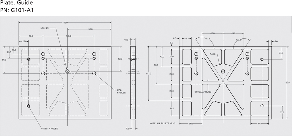
Figure 16-48
A figure presents three different views of the guide plate: front, side, and back. The front and back view portray the plate as a rectangular model. The back is shown to be divided into several symmetric sections. The same is depicted as hidden regions in the front view. The length of the rectangular body is 190.0. As per the front view, the rectangular body has two holes on the left, at a distance of 20.0 from the left edge. These are marked M6 cross 1.4 holes. Another hole is almost. Further two sets of three holes each are provided, four of them bigger and two smaller. The bigger holes together form a rectangular shape, and the two small holes are placed below the top vertices (holes) of the rectangular shaped formed earlier. The holes are placed such that, their centers are aligned both vertically and horizontally. The first set of three holes are at a distance of 50.0 from the left edge and the second set of three holes are at a distance of 105.0 from the first set of holes. The bigger holes are of diameter 7.0. Another hole is marked between these two sets, located at a distance of 52.0 from the top edge of the rectangular body of the plate. It is at a distance of 90.0 from the right edge of the rectangular body. This hole is of type M8 cross 1.25. The side view of the plate shows that the entire thickness of the plate is 10.0, while the sections at the back is of thickness 7.0. The back view shows the dimensions of the several sections made. The width of the plate is marked 150.0. On the side, where the plate has two holes four rectangular sections of equal sizes are made one below the other, such that, the holes fall within the boundaries of the first and the last rectangles. The holes are at a distance of 27.0 from their nearest edges. The rectangles are at a distance of 6.0 from the nearest edge. The length of the rectangles are 37.0. On the other side of the plate, four rectangular sections are placed one below the other. The top and bottom rectangles are of length 31.0 and the middle are of length 29.0. The width of the rectangles are 19.0. In the middle of the plate, four triangle-shaped and four trapezium-shaped sections are made.
Figure 16-49
Two different views of the bar that runs at the back of the guide plate are given. The front view resembles a horizontal bar with four holes. The width of the bar is 18.0. The holes are of types M6 cross 1. The two holes near the either end of the bar are at a distance of 13.00 from the side. The centers of all the four holes are at a distance of 9.0 from the top edge of the bar. The second hole is at a distance of 80.00 from the left end and the third hole is at a distance of 105.00 from the second hole. The side view of the bar also resembles a horizontal bar, whose thickness is slightly higher in the middle region, excluding 27.0 distance from either end. The difference in thickness is 6.0 on both sides. In this view, three other holes of type M6 cross 1 are noticed. The holes near the either end of the bar are at a distance of 50.0 from the respective ends. The entire length of the bar is 265.00. The distance between two adjacent hole is 82.50. The entire width of the bar in this view is 9.0.
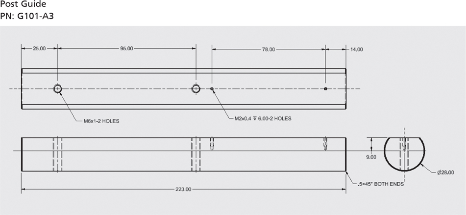
Figure 16-50
Two different views of the post guide are presented. In the first view, four holes are noticed in total. 2 of them are bigger of type M 6 cross 1 and two of them are smaller of type M2 cross 0.4. The two bigger holes are next to each other at a distance of 95.00 apart from one another. The bigger hole nearest to the edge of the bar is at a distance of 25.00 from the edge. The two smaller holes are at a distance of 78.00 apart from one another. The hole nearest to the edge of the bar is at a distance of 14.00 from the edge. In the second view, the entire length of the bar is marked as 223.00. The ends are filleted, measuring 0.5 times 45 degrees. Another view shows the radius of part as 28.00.
Figure 16-51
The front and side views of the ruler, PN: RR-6-40, are shown. In the front view, the ruler resembles a normal ruler or a scale, with readings ranging from 0 to 7 (7 major places). Two holes of radius 1.5 each are located at either end of the scale. The readings marked on the scale is comprised of 70 places (minor), each of width 1.0. The distance between two major readings is 10.0, while half of it is marked 5. The reading starts after the hole on one end, at a distance of 5.0 from the end. The distance between the centers of the two holes on either side is 78.0. The distance between the center of a hole and the bottom edge of the ruler is 4.0. The side view indicates that the width of the scale is 8.0 and the thickness is 0.7.
Figure 16-52
Figure 16-53
A figure depicts the front and side view of the screw part, PN: G103-2. The front view depicts the screw as two concentric circles, with hidden parts in the middle, denoted using dashed circles. The diameter of the outer circle is 30.0 and the diameter of the inner circle is 21.0. The side view of the screw is depicted as follows. The model is constructed using a horizontal bar connected to a rhombus on its left, which in turn is attached to a rectangle. The connection between the bar and the rhombus is three-fold (using three small rectangular shapes). The entire length of the screw is 153.0. The bar's loose ends are chamfered, 0.5 times 45 degrees. The width of the rectangle at the left is 22.0. The horizontal length considering the rectangle and the rhombus is 32.0. The diameter of the hole running inside the body of the screw is marked 12.0. The type is M10 cross 1.5.
Figure 16-54
A figure shows two views of the plate. The shape and outline of this plate resembles the pop-tab on a beverage's tin can lid. The shape encloses two circles, one bigger on the larger end of the pop-tab shape and the smaller on the other end. The diameter of the bigger hole is 29.0 and the smaller hole is 13.0. The radius of the surface of the plate on the wider end is 17.0 and the radius of the surface of the plate on the narrower end is 9.0. This is of type M6 cross 1. The distance between the centers of the holes is 45.0. The side view of the plate resembles a horizontal bar of thickness 15.0. It has a single hole of diameter 3.5. The center of the hole is at a distance of 7.5 from either the top or the bottom.
Figure 16-55