
Chapter 13. Implementing Point-to-Point WANs
This chapter covers the following exam topics:
3.0 WAN Technologies
3.1 Configure and verify PPP and MLPPP on WAN interfaces using local authentication
Leased-line WANs—also known as serial links—require much less thought than many other topics, at least to the depth required for the CCENT and CCNA R&S exams. That simplicity allows the Cisco exams to discuss leased lines briefly for the ICND1 exam, while using leased lines as part of larger discussions of IP routing.
This chapter finally takes the discussion of leased-line WANs deeper than has been discussed so far. This chapter briefly repeats the leased line concepts from the ICND1 book, to lay a foundation to discuss other concepts. More important, this chapter looks at the configuration, verification, and troubleshooting steps for leased lines that use the familiar High-level Data Link Control (HDLC) data-link protocol and the Point-to-Point Protocol (PPP).
This chapter breaks the material down into three major sections. The first looks at leased-line WANS that use HDLC, by reviewing and adding details about the physical links themselves, along with HDLC (and related) configuration. The second major section discusses PPP, an alternate data-link protocol that you can use instead of HDLC, with a focus on concepts and configuration. The final major section then discusses typical root causes of serial link problems and how to find those problems.
“Do I Know This Already?” Quiz
Take the quiz (either here, or use the PCPT software) if you want to use the score to help you decide how much time to spend on this chapter. The answers are at the bottom of the page following the quiz, and the explanations are in DVD Appendix C and in the PCPT software.

1. In the cabling for a leased line, which of the following usually connects to a four-wire line provided by a telco?
a. Router serial interface without internal CSU/DSU
b. CSU/DSU
c. Router serial interface with internal transceiver
d. Switch serial interface
2. Two routers connect with a serial link, each using its S0/0/0 interface. The link is currently working using PPP. The network engineer wants to migrate to use the Cisco-proprietary HDLC that includes a protocol type field. Which of the following commands can be used to migrate to HDLC successfully? (Choose two answers.)
a. encapsulation hdlc
b. encapsulation cisco-hdlc
c. no encapsulation ppp
d. encapsulation-type auto
3. Which of the following PPP authentication protocols authenticates a device on the other end of a link without sending any password information in clear text?
a. MD5
b. PAP
c. CHAP
d. DES
4. Two routers have no initial configuration whatsoever. They are connected in a lab using a DTE cable connected to R1 and a DCE cable connected to R2, with the DTE and DCE cables then connected to each other. The engineer wants to create a working PPP link by configuring both routers. Which of the following commands are required in the R1 configuration for the link to reach a state in which R1 can ping R2’s serial IP address, assuming that the physical back-to-back link physically works? (Choose two answers.)
a. encapsulation ppp
b. no encapsulation hdlc
c. clock rate
d. ip address
5. Consider the following excerpt from the output of a show command:
Serial0/0/1 is up, line protocol is up
Hardware is GT96K Serial
Internet address is 192.168.2.1/24
MTU 1500 bytes, BW 1544 Kbit, DLY 20000 usec,
reliability 255/255, txload 1/255, rxload 1/255
Encapsulation PPP, LCP Open
Open: CDPCP, IPCP, loopback not set
Which of the following are true about this router’s S0/0/1 interface? (Choose two answers.)
a. The interface is using HDLC.
b. The interface is using PPP.
c. The interface currently cannot pass IPv4 traffic.
d. The link should be able to pass PPP frames at the present time.
6. Two routers, R1 and R2, connect to each other using three serial links. The network engineer configures these links to be part of the same multilink PPP group, along with configuring CHAP configuration, IPv4, and OSPFv2 using interface configuration. Which of the following answers list a configuration command along with the correct configuration mode for that command? (Choose two answers.)
a. encapsulation ppp while in multilink interface configuration mode
b. ip address address mask while in serial interface configuration mode
c. ppp authentication chap while in multilink interface configuration mode
d. ip ospf 1 area 0 while in serial interface configuration mode
e. ppp multilink while in serial interface configuration mode
7. Consider the following excerpt from the output of a show interfaces command on an interface configured to use PPP:
Serial0/0/1 is up, line protocol is down
Hardware is GT96K Serial
Internet address is 192.168.2.1/24
A ping of the IP address on the other end of the link fails. Which of the following are reasons for the failure, assuming that the problem listed in the answer is the only problem with the link? (Choose two answers.)
a. The CSU/DSU connected to the other router is not powered on.
b. The IP address on the router at the other end of the link is not in subnet 192.168.2.0/24.
c. CHAP authentication failed.
d. The router on the other end of the link has been configured to use HDLC.
e. None of the above.
Answers to the “Do I Know This Already?” quiz:
1 B 2 A, C 3 C 4 A, D 5 B, D 6 A, E 7 C, D
Foundation Topics
Leased-Line WANs with HDLC
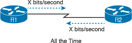
A physical leased-line WAN works a lot like in an Ethernet crossover cable connecting two routers, but with no distance limitations. As shown in Figure 13-1, each router can send at any time (full duplex). The speed is also symmetric, meaning that both routers send bits at the same speed.
Although the leased line provides a physical layer bit transmission facility, routers also need to use a data link protocol on the WAN link to send bits over the link. The story should be familiar by now: routers receive frames in LAN interfaces, and then the router de-encapsulates the network layer packet. Before forwarding the packet, the router encapsulates the packet inside a WAN data link protocol like High-level Data Link Control (HDLC), as shown at Step 2 of Figure 13-2.

These first two figures review some of the Layer 1 and Layer 2 details, respectively, of leased-line WANs. This first major section of this chapter begins by discussing these links again, first with the Layer 1 details, followed by the Layer 2 details. This section ends with an explanation of HDLC configuration details.
Layer 1 Leased Lines
Leased lines have been around a long time, roughly 20 years longer than LANs. However, they still exist today as a WAN service.
As a result of their long history in the market, the networking world has used a large number of different terms. First, the term leased line refers to the fact that the company using the leased line does not own the line, but instead pays a monthly lease fee to use it. Often, you lease the service from a telephone company, or telco. However, many people today use the generic term service provider to refer to a company that provides any form of WAN connectivity, including Internet services. Table 13-2 lists some of those names so that you can understand the different terms you will encounter in a real networking job.

The Physical Components of a Leased Line
To create a leased line, the telco must create some physical transmission path between the two routers on the ends of the link. The physical cabling must leave the buildings where each router sits. Then the telco must create the equivalent of a two-pair circuit from end to end, with one circuit to send data in each direction (full duplex). Figure 13-3 shows one such example, in which the telco uses a couple of traditional central office (CO) switches to create a short leased line between two routers.

The details in the center of Figure 13-3 probably show more than you ever need to know about leased-line WANs, at least from the enterprise customer perspective. More commonly, most network engineers think more about a leased line from the perspective of Figure 13-4, which shows a few key components and terms for the equipment on the ends of a leased line, as follows:
Customer premises equipment (CPE): This telco term refers to the gear that sits at their customers’ sites on the ends on the link.
Channel service unit/data service unit (CSU/DSU): This device provides a function called clocking, in which it physically controls the speed and timing at which the router serial interface sends and receives each bit over the serial cable.
Serial cable: This is a short cable that connects the CSU and the router serial interface.

The CPE includes several separately orderable parts. When using an external CSU/DSU, a serial cable must be used to connect the CSU to the router serial interface. These serial interfaces usually exist as part of a removable card on the router, called either WAN interface cards (WIC), High-speed WICs (HWIC), or Network Interface Modules (NIM). Most of the serial interfaces use one style (size/shape) of physical connector called a smart serial connector, whereas the CSU has one of several other types of connectors. So, when installing the leased line, the engineer must choose the correct cable type, with connectors to match the WIC on one end and the CSU/DSU on the other. Figure 13-5 shows a drawing of one type of serial cable, with the smart serial connector on the left, and the popular V.35 connector on the right. The figure shows a side view of the entire cable, plus direct views into the connector on the ends of the cable.

Today, many leased lines make use of Cisco WICs with an integrated CSU/DSU. That is, the WIC hardware includes the same functions as a CSU/DSU, so an external CSU/DSU is not needed. Compared to Figure 13-4, the external CSU/DSU and serial cable on each end are not needed, with the cable from the telco connecting directly to the WIC.
Figure 13-6 shows a photo of a router with two NIM slots. Each slot currently shows a faceplate with no NIM cards installed. The foreground of the figure shows a NIM with two serial ports, with smart serial interfaces. The cable end on the left of the drawing in Figure 13-5 would attach to one of these smart serial ports on the NIM in Figure 13-6.

Telcos offer a wide variety of speeds for leased lines. However, a telco customer cannot pick just any speed. Instead, the speeds follow the standards of an age-old technology called the T-carrier system.
Back in the 1950s and 1960s, the U.S.-based Bell companies developed and deployed digital voice and the T-carrier system. As part of that work, they standardized different transmission speeds, including 64 Kbps, 1.544 Mbps, and 44.736 Mbps.
Those same Bell companies developed time-division multiplexing (TDM) technology that let them combine multiples of these base speeds onto a single line. For instance, one popular standard, a Digital Signal level 1 (DS1), or T1, combines 24 DS0s (at 64 Kbps) plus 8 Kbps of overhead into one physical line that runs at 1.544 Mbps. However, to allow flexibility of speeds offered to customers, the telco could install a T1 line to many sites, but run some at slower speeds and some at faster speeds—as long as those speeds were multiples of 64 Kbps.
Now back to the idea of the speed of a leased line. What can you actually buy? Basically, at slower speeds, you get any multiple of 64 Kbps, up to T1 speed. At faster speeds, you can get multiples of T1 speed, up to T3 speed. Table 13-3 summarizes the speeds typically seen in the United States, with a few from Europe.

The Role of the CSU/DSU
For our last bit of discussion about WAN links in a working enterprise internetwork, next consider the role of the CSU/DSU (called CSU for short). For the sake of discussion, the next few paragraphs, leading up to Figure 13-7, assume a leased line with external CSU/DSUs, like earlier in Figure 13-4.

The CSU sits between the telco leased line and the router; it understands both worlds and their conventions at Layer 1. On the telco side, that means the CSU connects to the line from the telco, so it must understand all these details about the T-carrier system, TDM, and the speed used by the telco. On the router side of the equation, the CSU connects to the router, with roles called the DCE and DTE, respectively. The CSU, acting as DCE (data circuit-terminating equipment), controls the speed of the router serial interface. The router, acting as DTE (data terminal equipment), is controlled by the clocking signals from the CSU (DCE). That is, the CSU tells the router when to send and receive bits; the router attempts to send and receive bits only when the DCE creates the correct electrical impulses (called clocking) on the cable. Figure 13-7 shows a diagram of those main concepts of the role of the CSU/DSU.
Building a WAN Link in a Lab
On a practical note, to prepare for the CCENT and CCNA R&S exams, you might choose to buy some used router and switch hardware for hands-on practice. If you do, you can create the equivalent of a leased line, without a real leased line from a telco, and without CSU/DSUs, just using a cabling trick. This short discussion tells you enough information to create a WAN link in your home lab.
First, when building a real WAN link with a real telco facility between sites, the serial cables normally used between a router and an external CSU/DSU are called DTE cables. That is, the serial cables in earlier Figure 13-4 are DTE cables.
You can create an equivalent WAN link just by connecting two routers’ serial interfaces using one DTE cable and a slightly different DCE cable, with no CSUs and with no leased line from the telco. The DCE cable has a female connector, and the DTE cable has a male connector, which allows the two cables to be attached directly. That completes the physical connection, providing a path for the data. The DCE cable also does the equivalent of an Ethernet crossover cable by swapping the transmit and receive wire pairs, as shown in Figure 13-8.

The figure shows the cable details at the top, with the wiring details at the bottom. In particular, at the bottom of the figure, note that the DTE serial cable acts as a straight-through cable and does not swap the transmit and receive pair, whereas the DCE cable does swap the pairs.
Note
Many vendors, for convenience, sell a single cable that combines the two cables shown in Figure 13-8 into a single cable. Search online for “Cisco serial crossover” to find examples.
Finally, to make the link work, the router with the DCE cable installed must provide clocking. A router serial interface can provide clocking, but it can do so only if a DCE cable is connected to the interface and by the configuration of the clock rate command. Newer IOS versions will sense the presence of a DCE cable and automatically set a clock rate, so that the link will work, but old IOS versions require that you configure the clock rate command.
Layer 2 Leased Lines with HDLC
A leased line provides a Layer 1 service. It promises to deliver bits between the devices connected to the leased line. However, the leased line itself does not define a data link layer protocol to be used on the leased line. HDLC provides one option for a data link protocol for a leased line.
HDLC has only a few big functions to perform with the simple point-to-point topology of a point-to-point leased line. First, the frame header lets the receiving router know that a new frame is coming. Plus, like all the other data link protocols, the HDLC trailer has a Frame Check Sequence (FCS) field that the receiving router can use to decide whether the frame had errors in transit, and if so, discard the frame.
Cisco adds another function to the ISO standard HDLC protocol by adding an extra field (a Type field) to the HDLC header, creating a Cisco-specific version of HDLC, as shown in Figure 13-9. The Type field allows Cisco routers to support multiple types of network layer packets to cross the HDLC link. For example, an HDLC link between two Cisco routers can forward both IPv4 and IPv6 packets because the Type field can identify which type of packet is encapsulated inside each HDLC frame.

Today, the HDLC Address and Control fields have little work to do. For instance, with only two routers on a link, when a router sends a frame, it is clear that the frame is sent to the only other router on the link. Both the Address and Control fields had important purposes in years past, but today they are unimportant.
Routers use HDLC just like any other data link protocol used by routers: to move packets to the next router. Figure 13-10 shows three familiar routing steps, with the role of HDLC sitting at Step 2.
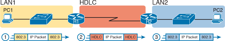
Here is a walkthrough of the steps in the figure:
1. To send the IP packet to router R1, PC1 encapsulates the IP packet in an Ethernet frame.
2. Router R1 de-encapsulates (removes) the IP packet, encapsulates the packet into an HDLC frame using an HDLC header and trailer, and forwards the HDLC frame to router R2.
3. Router R2 de-encapsulates (removes) the IP packet, encapsulates the packet into an Ethernet frame, and forwards the Ethernet frame to PC2.
In summary, a leased line with HDLC creates a WAN link between two routers so that they can forward packets for the devices on the attached LANs. The leased line itself provides the physical means to transmit the bits, in both directions. The HDLC frames provide the means to encapsulate the network layer packet correctly so it crosses the link between routers.
Configuring HDLC
Think back to router Ethernet interfaces for a moment. Router Ethernet interfaces require no configuration related to Layers 1 and 2 for the interface to be up and working, forwarding IP traffic. The Layer 1 details occur by default once the cabling has been installed correctly. Router Ethernet interfaces, of course, use Ethernet as the data link protocol by default. The router only needs to configure an IP address on the interface, and possibly enable the interface with the no shutdown command if the interface is in an “administratively down” state.
Similarly, serial interfaces on Cisco routers need no specific Layer 1 or 2 configuration commands. For Layer 1, the cabling needs to be completed, of course, but the router attempts to use the serial interface once the no shutdown command is configured. For Layer 2, IOS defaults to use HDLC on serial interfaces. As on Ethernet interfaces, router serial interfaces usually only need an ip address command, and possibly the no shutdown command, assuming both routers’ interfaces otherwise have default settings.
However, many optional commands exist for serial links. The following list outlines some configuration steps, listing the conditions for which some commands are needed, plus commands that are purely optional:
Step 1. Use the ip address address mask command in interface configuration mode to configure the interface IP address.
Step 2. The following tasks are required only when the specifically listed conditions are true:
A. If an encapsulation protocol interface subcommand already exists, for a non-HDLC protocol, use the encapsulation hdlc command in interface configuration mode to enable HDLC. Alternatively, use the no encapsulation protocol command in interface configuration mode to use the default setting of HDLC as the data link protocol.
B. If the interface line status is administratively down, use the no shutdown command in interface configuration mode to enable the interface.
C. If the serial link is a back-to-back serial link in a lab (or a simulator), use the clock rate speed command in interface configuration mode to configure the clocking rate. Use this command only on the one router with the DCE cable (per the show controllers serial number command).
Step 3. The following steps are always optional and have no impact on whether the link works and passes IP traffic:
A. Use the bandwidth speed-in-kbps command in interface configuration mode to configure the link’s documented speed so that it matches the actual clock rate of the link.
B. For documentation purposes, use the description text command in interface configuration mode to configure a description of the purpose of the interface.
In practice, when you configure a Cisco router with no preexisting interface configuration and install a normal production serial link with CSU/DSUs, the ip address and no shutdown commands are likely the only configuration commands you would need.
Figure 13-11 shows a sample internetwork, and Example 13-1 shows the matching HDLC configuration. In this case, the serial link was created with a back-to-back serial link in a lab, requiring Steps 1 (ip address) and 2C (clock rate) from the preceding list. It also shows optional Step 3B (description).

Example 13-1 HDLC Configuration
R1# show running-config
! Note - only the related lines are shown
interface GigabitEthernet0/0
ip address 192.168.1.1 255.255.255.0
!
interface Serial0/0/0
ip address 192.168.2.1 255.255.255.0
description link to R2
clock rate 2000000
!
router eigrp 1
network 192.168.1.0
network 192.168.2.0
The configuration on R1 is relatively simple. The matching configuration on R2’s S0/0/1 interface simply needs an ip address command plus the default settings of encapsulation hdlc and no shutdown. The clock rate command would not be needed on R2 because R1 has the DCE cable, so R2 must be connected to a DTE cable.
Example 13-2 lists two commands that confirm the configuration on R1 and some other default settings. First, it lists the output from the show controllers command for S0/0/0, which confirms that R1 indeed has a DCE cable installed and that the clock rate has been set to 2000000 bps. The show interfaces S0/0/0 command lists the various configuration settings near the top, including the default encapsulation value (HDLC) and default bandwidth setting on a serial interface (1544, meaning 1544 Kbps or 1.544 Mbps). It also lists the IP address, prefix-style mask (/24), and description, as configured in Example 13-1.
Example 13-2 Verifying the Configuration Settings on R1
R1# show controllers serial 0/0/0
Interface Serial0/0/0
Hardware is SCC
DCE V.35, clock rate 2000000
! lines omitted for brevity
R1# show interfaces s0/0/0
Serial0/0/0 is up, line protocol is up
Hardware is WIC MBRD Serial
Description: link to R2
Internet address is 192.168.2.1/24
MTU 1500 bytes, BW 1544 Kbit/sec, DLY 20000 usec,
reliability 255/255, txload 1/255, rxload 1/255
Encapsulation HDLC, loopback not set
Keepalive set (10 sec)
Last input 00:00:01, output 00:00:00, output hang never
Last clearing of "show interface" counters never
Input queue: 0/75/0/0 (size/max/drops/flushes); Total output drops: 0
Queueing strategy: fifo
Output queue: 0/40 (size/max)
5 minute input rate 0 bits/sec, 0 packets/sec
5 minute output rate 0 bits/sec, 0 packets/sec
276 packets input, 19885 bytes, 0 no buffer
Received 96 broadcasts (0 IP multicasts)
0 runts, 0 giants, 0 throttles
0 input errors, 0 CRC, 0 frame, 0 overrun, 0 ignored, 0 abort
284 packets output, 19290 bytes, 0 underruns
0 output errors, 0 collisions, 5 interface resets
0 unknown protocol drops
0 output buffer failures, 0 output buffers swapped out
7 carrier transitions
DCD=up DSR=up DTR=up RTS=up CTS=up
Finally, the router uses the serial interface only if it reaches an up/up interface status, as shown in the first line of the output of the show interfaces S0/0/0 command in Example 13-2. Generally speaking, the first status word refers to Layer 1 status, and the second refers to Layer 2 status. For a quicker look at the interface status, instead use either the show ip interface brief or show interfaces description commands, as listed in Example 13-3.
Example 13-3 Brief Lists of Interfaces and Interface Status
R1# show ip interface brief
Interface IP-Address OK? Method Status Protocol
GigabitEthernet0/0 192.168.1.1 YES manual up up
GigabitEthernet0/1 unassigned YES manual administratively down down
Serial0/0/0 192.168.2.1 YES manual up up
Serial0/0/1 unassigned YES NVRAM administratively down down
Serial0/1/0 unassigned YES NVRAM administratively down down
Serial0/1/1 unassigned YES NVRAM administratively down down
R1# show interfaces description
Interface Status Protocol Description
Gi0/0 up up LAN at Site 1
Gi0/1 admin down down
Se0/0/0 up up link to R2
Se0/0/1 admin down down
Se0/1/0 admin down down
Se0/1/1 admin down down
Leased-Line WANs with PPP
Point-to-Point Protocol (PPP) plays the same role as HDLC: a data link protocol for use on serial links. However, HDLC was created for a world without routers. In contrast, PPP, defined in the 1990s, was designed with routers, TCP/IP, and other network layer protocols in mind, with many more advanced features.
This second major section of this chapter first discusses PPP concepts, including one example of a more advanced PPP feature (authentication). This section ends with some configuration examples using PPP.
PPP Concepts
PPP provides several basic but important functions that are useful on a leased line that connects two devices:

![]() Definition of a header and trailer that allows delivery of a data frame over the link
Definition of a header and trailer that allows delivery of a data frame over the link
![]() Support for both synchronous and asynchronous links
Support for both synchronous and asynchronous links
![]() A protocol Type field in the header, allowing multiple Layer 3 protocols to pass over the same link
A protocol Type field in the header, allowing multiple Layer 3 protocols to pass over the same link
![]() Built-in authentication tools: Password Authentication Protocol (PAP) and Challenge Handshake Authentication Protocol (CHAP)
Built-in authentication tools: Password Authentication Protocol (PAP) and Challenge Handshake Authentication Protocol (CHAP)
![]() Control protocols for each higher-layer protocol that rides over PPP, allowing easier integration and support of those protocols
Control protocols for each higher-layer protocol that rides over PPP, allowing easier integration and support of those protocols
The next several pages take a closer look at the protocol field, authentication, and the control protocols.
PPP Framing
Unlike the standard version of HDLC, the PPP standard defines a protocol field. The protocol field identifies the type of packet inside the frame. When PPP was created, this field allowed packets from the many different Layer 3 protocols to pass over a single link. Today, the protocol Type field still provides the same function, usually supporting packets for the two different versions of IP (IPv4 and IPv6). Figure 13-12 shows the PPP framing, which happens to mirror the Cisco-proprietary HDLC framing that includes a protocol Type field (as shown earlier in Figure 13-9).

PPP Control Protocols
In addition to HDLC-like framing, PPP defines a set of Layer 2 control protocols that perform various link control functions. The idea of these extra protocols works a little like how Ethernet includes additional protocols like Spanning Tree Protocol (STP). Ethernet has headers and trailers to deliver frames, plus it defines overhead protocols like STP to help make the frame forwarding process work better. Likewise, PPP defines the frame format in Figure 13-12, plus it defines other protocols to help manage and control the serial link.
PPP separates these control protocols into two main categories:
![]() Link Control Protocol (LCP): This one protocol has several different individual functions, each focused on the data link itself, ignoring the Layer 3 protocol sent across the link.
Link Control Protocol (LCP): This one protocol has several different individual functions, each focused on the data link itself, ignoring the Layer 3 protocol sent across the link.
![]() Network Control Protocols (NCP): This is a category of protocols, one per network layer protocol. Each protocol performs functions specific to its related Layer 3 protocol.
Network Control Protocols (NCP): This is a category of protocols, one per network layer protocol. Each protocol performs functions specific to its related Layer 3 protocol.
The PPP LCP implements the control functions that work the same regardless of the Layer 3 protocol. For features related to any higher-layer protocols, usually Layer 3 protocols, PPP uses a series of PPP control protocols (CP), such as IP Control Protocol (IPCP). PPP uses one instance of LCP per link and one NCP for each Layer 3 protocol defined on the link. For example, on a PPP link using IPv4, IPv6, and Cisco Discovery Protocol (CDP), the link uses one instance of LCP plus IPCP (for IPv4), IPv6CP (for IPv6), and CDPCP (for CDP).
Table 13-4 summarizes the functions of LCP, gives the LCP feature names, and describes the features briefly. Following the table, the text explains one of the features, PPP authentication, in more detail. Later, the section “Implementing Multilink PPP” discusses the Multilink PPP (MLPPP) feature.

PPP Authentication
In networking, authentication gives one device a way to confirm that another device is truly the correct and approved device with which communications should occur. In other words, authentication confirms that the other party is the authentic other party, and not some imposter.
For instance, with PPP, if R1 and R2 are supposed to be communicating over a serial link, R1 might want R2 to somehow prove that the device claiming to be R2 really is R2. In that scenario, R1 wants to authenticate R2, with the authentication process providing a way for R2 to prove its identity.
WAN authentication is most often needed when dial lines are used. However, the configuration of the authentication features remains the same whether a leased line or dial line is used.
PPP defines two authentication protocols: PAP and CHAP. Both protocols require the exchange of messages between devices, but with different details. With PAP, the process works with the to-be-authenticated device starting the messages, claiming to be legitimate by listing a secret password in clear text, as shown in Figure 13-13.

In the figure, when the link comes up, authentication takes two steps. At Step 1, Barney sends the shared password in clear text. Fred, who wants to authenticate Barney—that is, confirm that Barney is the real Barney—sees the password. Fred, configured with Barney’s name and password, checks that configuration, confirming that it is the correct password, and sends back an acknowledgment that Barney has passed the authentication process.
CHAP, a much more secure option, uses different messages, and it hides the password. With CHAP, the device doing the authentication (Fred) begins with a message called a challenge, which asks the other device to reply. The big difference is that the second message in the flow (as shown in Figure 13-14) hides the authentication password by instead sending a hashed version of the password. Router Fred has been preconfigured with Barney’s name and password in such a way that Fred can confirm that the hashed password sent by Barney is indeed the same password that Fred lists in his configuration for Barney. If the password is indeed the correct password, Fred sends back a third message to confirm the successful authentication of Barney.

Both Figures 13-13 and 13-14 show authentication flows when authentication works. When it fails (for instance, if the passwords do not match), a different final message flows. Also, if the authentication fails, PPP leaves the interface in an up/down state, and the router cannot forward and receive frames on the interface.
PAP flows are much less secure than CHAP because PAP sends the hostname and password in clear text in the message. These can be read easily if someone places a tracing tool in the circuit. CHAP instead uses a one-way hash algorithm, called message digest 5 (MD5), with input to the algorithm being a password that never crosses the link plus a shared random number.
The CHAP process also uses a hash value only one time so that an attacker cannot just make a copy of the hashed value and send it at a later date. To make that work, the CHAP challenge (the first CHAP message) states a random number. The challenged router runs the hash algorithm using the just-learned random number and the secret password as input, and sends the results back to the router that sent the challenge. The router that sent the challenge runs the same algorithm using the random number (sent across the link) and the password (as stored locally); if the results match, the passwords must match. Later, the next time the authentication process work occurs, the authenticating router generates and uses a different random number.
PAP and CHAP are a few examples of the work done by PPP’s LCP. The next topic looks at how to configure and verify PPP.
Implementing PPP
Configuring PPP, as compared to HDLC, requires only one change: using the encapsulation ppp command on both ends of the link. As with HDLC, other items can be optionally configured, such as the interface bandwidth, and a description of the interface. And of course, the interface must be enabled (no shutdown). But the configuration to migrate from HDLC to PPP just requires the encapsulation ppp command on both routers’ serial interfaces.
Example 13-4 shows a simple configuration using the two routers shown in Figure 13-11, the same internetwork used for the HDLC example. The example includes the IP address configuration, but the IP addresses do not have to be configured for PPP to work.
Example 13-4 Basic PPP Configuration
! The example starts with router R1
interface Serial0/0/0
ip address 192.168.2.1 255.255.255.0
encapsulation ppp
clockrate 2000000
! Next, the configuration on router R2
interface Serial0/0/1
ip address 192.168.2.2 255.255.255.0
encapsulation ppp
The one show command that lists PPP details is the show interfaces command, with an example from R1 listed in Example 13-5. The output looks just like it does for HDLC up until the first highlighted line in the example. The two highlighted lines confirm the configuration (“Encapsulation PPP”). These lines also confirm that LCP has completed its work successfully, as noted with the “LCP Open” phrase. Finally, the output lists the fact that two CPs, CDPCP and IPCP, have also successfully been enabled—all good indications that PPP is working properly.
Example 13-5 Finding PPP, LCP, and NCP Status with show interfaces
R1# show interfaces serial 0/0/0
Serial0/0/0 is up, line protocol is up
Hardware is WIC MBRD Serial
Description: link to R2
Internet address is 192.168.2.1/24
MTU 1500 bytes, BW 1544 Kbit/sec, DLY 20000 usec,
reliability 255/255, txload 1/255, rxload 1/255
Encapsulation PPP, LCP Open
Open: IPCP, CDPCP, loopback not set
! Lines omitted for brevity
Implementing PPP CHAP
The simplest version of CHAP configuration requires only a few commands. The configuration uses a password configured on each router. (As an alternative, the password could be configured on an external authentication, authorization, and accounting [AAA] server outside the router.)
To configure PPP along with CHAP on an interface that has all default configuration on the serial interfaces of both routers, follow these steps:
Step 1. Use the encapsulation ppp command in interface configuration mode, on the serial interfaces on both routers, to enable PPP on the interfaces.
Step 2. Define the usernames and passwords used by the two routers:
A. Use the hostname name command in global configuration mode on each router, to set the local router’s name to use when authenticating.
B. Use the username name password password command in global configuration mode on each router, to define the name (case-sensitive) used by the neighboring router, and the matching password (case-sensitive). (The name in the username command should match the name in the neighboring router’s hostname command.)
Step 3. Use the ppp authentication chap command in interface configuration mode on each router to enable CHAP on each interface.
Figure 13-15 shows the configuration on both R1 and R2 to both enable PPP and add CHAP to the link. The figure shows how the name in the hostname command on one router must match the username command on the other router. It also shows that the password defined in each username command must be the same (mypass in this case).

You can confirm that CHAP authentication has succeeded in a couple of ways. First, if CHAP authentication is enabled but CHAP authentication fails, the protocol status of the interface falls to a down state. To check that status, use the usual show interfaces [type number] command or show interfaces status command. Additionally, if CHAP is enabled but CHAP authentication fails, the show interfaces command does not list “LCP Open” as shown in this example. Example 13-6 lists the output of the show interfaces serial0/0/0 command from R1, with CHAP enabled per Figure 13-15, with CHAP working. However, note that this command does not tell us whether authentication has been configured or not.
Example 13-6 Confirming CHAP Authentication with show interfaces
R1# show interfaces serial 0/0/0
Serial0/0/0 is up, line protocol is up
Hardware is WIC MBRD Serial
Description: link to R2
Internet address is 192.168.2.1/24
MTU 1500 bytes, BW 1544 Kbit/sec, DLY 20000 usec,
reliability 255/255, txload 1/255, rxload 1/255
Encapsulation PPP, LCP Open
Open: IPCP, CDPCP, loopback not set
Keepalive set (10 sec)
! Lines omitted for brevity
R1# show ppp all
Interface/ID OPEN+ Nego* Fail- Stage Peer Address Peer Name
------------ --------------------- -------- --------------- --------------------
Se0/0/0 LCP+ CHAP+ IPCP+ CDP> LocalT 192.168.2.2 R2
The more obvious way to confirm that CHAP works is to use the show ppp all command, as shown at the end of Example 13-6. This command lists a single line per PPP connection in the router. The highlighted header in the example is the column where this command lists various PPP protocols and their status, with a plus sign (+) meaning that the listed protocol is OPEN, and a minus sign (–) meaning that the protocol has failed. The highlighted parts of this command in the example confirm that Serial0/0/0 uses PPP, with CHAP authentication, and that CHAP authentication worked (as proved by the OPEN status of the CHAP protocol).
Implementing PPP PAP
PAP configuration differs from CHAP configuration in a couple of ways. First, PAP uses the similar authentication ppp pap command instead of the authentication ppp chap command. Then, PAP configures the sent username/password pair much differently than CHAP. A router defines the username/password pair it will send using the ppp pap sent-username command, configured as an interface subcommand. Once sent, the other router receives that username/password pair, and compares those values with its various username password global commands. Figure 13-16 shows a completed configuration for two routers (R1 and R2), with emphasis on matching the ppp pap sent-username command on one router with the username password commands on the other router.

Example 13-7 now shows two commands used to verify PAP operation. In particular, note that the show interfaces command tells us nothing more and nothing less as compared to using CHAP authentication. The line protocol status being up confirms that authentication, if configured, worked. (However, nothing in the show interfaces command output tells us whether or not CHAP or PAP has been configured.) As with CHAP, the LCP status of Open also confirms that authentication worked, again assuming authentication is configured. However, just as is the case when using CHAP, or when using no authentication at all, this command does not confirm whether authentication has been configured or, if it is configured, which authentication protocol is used. The better confirmation comes from the show ppp all command at the bottom of the example, which identifies PAP as configured on interface Serial0/0/0, and in this case the protocol is OPEN, meaning that authentication worked.
Example 13-7 Configuring and Verifying PAP Authentication
R1# show interfaces serial 0/0/0
Serial0/0/0 is up, line protocol is up
Hardware is WIC MBRD Serial
Description: link to R2
Internet address is 192.168.2.1/24
MTU 1500 bytes, BW 1544 Kbit/sec, DLY 20000 usec,
reliability 255/255, txload 1/255, rxload 1/255
Encapsulation PPP, LCP Open
Open: IPCP, CDPCP, loopback not set
Keepalive set (10 sec)
! Lines omitted for brevity
R1# show ppp all
Interface/ID OPEN+ Nego* Fail- Stage Peer Address Peer Name
------------ --------------------- -------- --------------- --------------------
Se0/0/0 LCP+ PAP+ IPCP+ CDPC> LocalT 192.168.2.2 ciscouser2
Finally, note that you can configure the interface to try using the PAP process first, but if the other side does not support PAP, it then tries CHAP. You can configure to try PAP first or CHAP first. Just configure the commands to support both, and add the ppp authentication pap chap command to try PAP first, or the ppp authentication chap pap command to try CHAP first.
Implementing Multilink PPP
Network designers sometimes use multiple parallel serial links between two routers, rather than a single serial link. That motivation may be to improve availability, so if one link fails, at least the others are working. The motivation may be simple economics—it may be cheaper to install two or three parallel T1 lines (at about 1.5 Mbps each) rather than move up to the next faster type of line, a T3 line, using a fractional T3 service. Whatever the reasons, you end up with a design that looks like the design in Figure 13-17, with multiple serial links between two routers.

If the network engineer configures the parallel serial links as discussed so far in this chapter, each link has IP addresses and can be used to forward IP packets. To make that happen, the interior routing protocol would run over each of the parallel links, with routing protocol neighbor relationships formed over each link. As a result, each router would learn multiple routes to every remote destination subnet—one such route for each parallel link.
Figure 13-18 shows the concept of having multiple equal-metric routes, one for each of the parallel serial links. It shows the same design as Figure 13-17, with two links. R1 has one route for network 192.168.9.0/24 over the top link, and one over the bottom link. If using EIGRP, R1 would have two EIGRP neighbor relationships with R2, one over each link.

The Layer 3 routing logic in Cisco IOS will then balance packets across the multiple links using the routes as shown in the figure. By default, IOS balances on a destination-by-destination address basis—for instance, in Figure 13-18, all packets to 192.168.9.1 might flow over the top link, with all packets going to destination address 192.168.9.2 being routed over the lower link. IOS can be configured to balance on a packet-by-packet basis.
Using the Layer 3 features discussed in the last page or so works, and works well in many cases. However, PPP offers a feature that simplifies the Layer 3 operations in topologies that use multiple parallel PPP links, with a feature called Multilink PPP (MLPPP).
Multilink PPP Concepts
Multilink PPP (MLPPP) is a PPP feature useful when using multiple parallel serial links between two devices. It provides two important features. First, it reduces the Layer 3 complexity by making the multiple serial interfaces on each router look like a single interface from a Layer 3 perspective. Instead of multiple subnets between routers, with multiple routing protocol neighbor relationships, and multiple equal-metric routes learned for each remote subnet, routers would have one subnet between routers, one routing protocol neighbor relationship, and one route per destination subnet. Figure 13-19 shows these main ideas for the same physical topology shown in Figure 13-18, which has multiple physical links.

MLPPP makes the multiple physical links work like a single link by using a virtual interface called a multilink interface. The Layer 3 configuration (like IPv4 and IPv6 addresses and routing protocol interface subcommands) is added to the multilink interface. Then the configuration associates the physical serial interfaces with the multilink interface, connecting the Layer 2 logic that works with the multiple serial links with the Layer 3 logic that works on the single multilink interface.
In addition to simplifying Layer 3 details as just described, MLPPP balances the frames sent at Layer 2 over the multiple links. With MLPPP, a router’s Layer 3 forwarding logic forwards each packet out the multilink interface. When IOS internally routes a packet out a multilink interface, MLPPP load-balancing logic takes over, encapsulating the packet into a new data link frame, and load balancing the frame.
Interestingly, MLPPP load balances the data link frame by fragmenting the frame into multiple smaller frames, one per active link, as shown with the process in Figure 13-20. Steps 1 and 2 show normal routing, with an encapsulated IP packet arriving at Step 1, and the router making the usual routing decision at Step 2. However, with the packet exiting a multilink interface, MLPPP fragments the packet into pieces (called fragments), with a PPP header/trailer around each, with a few extra header bytes to manage the fragmentation process. The receiving router reassembles the fragments back into the original packet (Step 4), with normal IP routing shown at Step 5.

MLPPP’s load-balancing process allows for some small variations in the sizes of the fragments, but for the most part, Cisco routers will balance the bytes sent equally across the active links in the multilink bundle. For instance, if three links are active, the router forwards about one-third of the byte volume of traffic.
Configuring MLPPP
Implementing MLPPP requires a longer configuration than most features discussed in this book. So first, to set the context a bit, think about these main three configuration requirements for MLPPP:
Step 1. Configure matching multilink interfaces on the two routers, configuring the interface subcommands for all Layer 3 features (IPv4, IPv6, and routing protocol) under the multilink interfaces (and not on the serial interfaces).
Step 2. Configure the serial interfaces with all Layer 1 and 2 commands, like clock rate (Layer 1) and ppp authentication (Layer 2).
Step 3. Configure some PPP commands on both the multilink and serial interfaces, to both enable MLPPP and associate the multilink interface with the serial interfaces.
Figure 13-21 shows all the specific MLPPP commands in a working example. The example is based on the design in Figures 13-19 and 13-20. Note that for space, Figure 13-21 shows the configuration for only one of the two serial interfaces, but all serial interfaces would have the same subcommands when used for MLPPP.

First, focus on the six configuration commands noted with white highlight boxes in Figure 13-21 as pointed to with arrows. The interface multilink 1 command on each router creates the multilink interface on that router. The network engineer chooses the interface number, but the number must be the same on both routers, or the link will not work. Additionally, the multilink interfaces and the physical serial interfaces must all have both a ppp multilink group 1 command, and they must all again refer to that same number (1 in this example). Any number in range could be used, but the number must match with the commands highlighted in the figure.
Now look at the ip address commands. Note that the configuration shows IPv4 addresses configured on the multilink interfaces, but no IPv4 address at all on the serial interface. In short, the multilink interface has the Layer 3 configuration, and the serial interfaces do not. As a result, the routing and routing protocol logic will work with the multilink interface.
Finally, note that both the multilink and serial interfaces have two additional commands: encapsulation ppp (which enables PPP), and ppp multilink (which adds multilink support).
Note
Figure 13-21 shows only one serial interface, but each serial interface in the multilink group would need the same configuration.
Verifying MLPPP
To verify that an MLPPP interface is working, it helps to think about the Layer 3 features separately from Layer 1 and Layer 2 details. For Layer 3, all the usual IPv4, IPv6, and routing protocol commands will now list the multilink interface rather than the physical serial interfaces. You can also just ping the IP address on the other end of the multilink to test the link. Example 13-8 shows a few commands to confirm the current working state of the MLPPP link, taken from the working configuration in Figure 13-21.
Example 13-8 Verifying Layer 3 Operations with an MLPPP Multilink Interface
R1# show ip route
! Legend omitted for brevity
192.168.1.0/24 is variably subnetted, 2 subnets, 2 masks
C 192.168.1.0/24 is directly connected, GigabitEthernet0/0
L 192.168.1.1/32 is directly connected, GigabitEthernet0/0
192.168.5.0/24 is variably subnetted, 3 subnets, 2 masks
C 192.168.5.0/24 is directly connected, Multilink1
L 192.168.5.1/32 is directly connected, Multilink1
C 192.168.5.2/32 is directly connected, Multilink1
D 192.168.9.0/24 [90/1343488] via 192.168.5.2, 16:02:07, Multilink1
R1# show ip eigrp interfaces
EIGRP-IPv4 Interfaces for AS(1)
Xmit Queue PeerQ Mean Pacing Time Multicast Pending
Interface Peers Un/Reliable Un/Reliable SRTT Un/Reliable Flow Timer Routes
Mu1 1 0/0 0/0 1 0/8 50 0
Gi0/0 1 0/0 0/0 1 0/0 50 0
R1# show ip interface brief
Interface IP-Address OK? Method Status Protocol
Embedded-Service-Engine0/0 unassigned YES NVRAM administratively down down
GigabitEthernet0/0 192.168.1.1 YES manual up up
GigabitEthernet0/1 unassigned YES manual up up
Serial0/0/0 unassigned YES manual up up
Serial0/0/1 unassigned YES manual administratively down down
Serial0/1/0 unassigned YES NVRAM administratively down down
Serial0/1/1 unassigned YES NVRAM up up
Multilink1 192.168.5.1 YES manual up up
Working from the top of the example to the bottom, note that the IPv4 routing table lists interface multilink 1 as the outgoing interface in a variety of routes. However, the two serial interfaces are not listed at all, because they do not have IP addresses and the router’s routing logic works with the multilink interface instead. Similarly, the show ip eigrp interfaces command lists interfaces on which EIGRP is enabled, listing Mu1 (Multilink 1), and not listing either of the two serial interfaces in the MLPPP bundle. Finally, note that the show ip interface brief command does list both the serial interfaces and the multilink interface, but the output confirms that no IP address has been configured on the serial interfaces, as noted with the “unassigned” text under the IP-Address column.
Each multilink interface has a line and protocol status like any other interface, and if that status is up/up, IOS believes the multilink interface is working. By default, that working state implies that at least one of the physical links in the MLPPP group is also working—that is, some of the physical links can fail, and the multilink stays up. You can always directly verify the serial interfaces in the multilink group with the same commands discussed earlier in the chapter (show controllers, show interfaces). Additionally, the two commands in Example 13-9 give some insight into the specifics of MLPPP operation.
Example 13-9 Verifying Operational Details of an MLPPP Group
R1# show interfaces multilink 1
Multilink1 is up, line protocol is up
Hardware is multilink group interface
Internet address is 192.168.5.1/24
MTU 1500 bytes, BW 3088 Kbit/sec, DLY 20000 usec,
reliability 255/255, txload 1/255, rxload 1/255
Encapsulation PPP, LCP Open, multilink Open
Open: IPCP, CDPCP, loopback not set
Keepalive set (10 sec)
! lines omitted for brevity
R1# show ppp multilink
Multilink1
Bundle name: R2
Remote Username: R2
Remote Endpoint Discriminator: [1] R2
Local Username: R1
Local Endpoint Discriminator: [1] R1
Bundle up for 16:50:33, total bandwidth 3088, load 1/255
Receive buffer limit 24000 bytes, frag timeout 1000 ms
0/0 fragments/bytes in reassembly list
0 lost fragments, 96 reordered
0/0 discarded fragments/bytes, 0 lost received
0x654D7 received sequence, 0x654D5 sent sequence
Member links: 2 active, 0 inactive (max 255, min not set)
Se0/1/1, since 16:50:33
Se0/0/0, since 16:23:16
No inactive multilink interfaces
First, notice that the show interfaces multilink 1 command lists many familiar details and some mentions about multilink. In particular, the output shows the traditional line and protocol status, both in an up state, meaning that the interface is working. On the sixth line, the output mentioned a working multilink state of “Open” in the section about PPP control protocols, confirming that MLPPP is in effect.
Finally, the output of the show ppp multilink command identifies the links configured in each multilink bundle, as well as which ones are active. In this case, on R1, interfaces S0/0/0 and S0/1/1 are active, as highlighted at the bottom of the example. The timer to the side shows that both have been active a little over 16 hours. Seeing these two interfaces in the list confirms not only that the physical interfaces are working, but that the MLPPP configuration includes both of these links in multilink group 1.
Troubleshooting Serial Links
This final major section discusses how to isolate and find the root cause of problems related to topics covered earlier in this chapter. Also, this section does not attempt to repeat the IP troubleshooting coverage in Part II of this book, but it does point out some of the possible symptoms on a serial link when a Layer 3 subnet mismatch occurs on opposite ends of a serial link, which prevents the routers from routing packets over the serial link.
A simple ping command can determine whether a serial link can or cannot forward IP packets. A ping of the other router’s serial IP address—for example, a working ping 192.168.2.2 command on R1 in Figure 13-11, the figure used for both the HDLC and PPP configuration examples—proves that the link either works or does not.
If the ping does not work, the problem could be related to functions at Layer 1, 2, or 3. The best way to isolate which layer is the most likely cause is to examine the interface status codes described in Table 13-5.

The serial link verification and troubleshooting process should begin with a simple three-step process:
Step 1. From one router, ping the other router’s serial IP address.
Step 2. If the ping fails, examine the interface status on both routers and investigate problems related to the likely problem areas listed in Table 13-5.
Step 3. If the ping works, also verify that any routing protocols are exchanging routes over the link, as discussed in Chapter 11, “Troubleshooting IPv4 Routing Protocols.”
Note
The interface status codes can be found using the show interfaces, show ip interface brief, and show interfaces description commands.
The rest of this section explores the specific items to be examined when the ping fails, based on the combinations of interface status codes listed in Table 13-5.
Troubleshooting Layer 1 Problems
The interface status codes, or interface state, play a key role in isolating the root cause of problems on serial links. In fact, the status on both ends of the link may differ, so it is important to examine the status on both ends of the link to help determine the problem.
For example, a serial link fails when just one of the two routers has administratively disabled its serial interface with the shutdown interface subcommand. When one router shuts down its serial interface, the other router sits in a down/down state (line status down, line protocol status down), assuming the second router’s interface is not also shut down. The solution is to just configure a no shutdown interface configuration command on the interface.
A serial interface with a down line status on both ends of the serial link—that is, both ends in a down/down state—usually points to some Layer 1 problem. Figure 13-22 summarizes the most common causes of this state. In the figure, R2’s serial interface has no problems at all; the center and left side of the figure show common root causes that then result in R2’s serial interface being in a down/down state.

Troubleshooting Layer 2 Problems
Data link layer problems on serial links usually result in at least one of the routers having a serial interface status of up/down. In other words, the line status (the first status code) is up, while the second status (the line protocol status) is down. Table 13-6 lists some of these types of problems.

The first of these problems—a mismatch between the configured data link protocols—is easy to identify and fix. The show interfaces command lists the encapsulation type on about the seventh line of the output, so using this command on both routers can quickly identify the problem. Alternatively, a quick look at the configuration, plus remembering that HDLC is the default serial encapsulation, can confirm whether the encapsulations are mismatched. The solution is simple: Reconfigure one of the two routers to match the other router’s encapsulation command.
The other two root causes require a little more discussion to understand the issue and determine if they are the real root cause. The next two sections take a closer look at each.
Keepalive Failure
The router keepalive feature helps a router notice when a link is no longer functioning. Once a router believes the link no longer works, the router can bring down the interface, allowing the routing protocol to converge to use other routes it they exist.
The keepalive function on an interface causes routers to send keepalive messages to each other every keepalive interval, defaulting to 10 seconds. For instance, on a serial link between R1 and R2, R1 sends a keepalive message every 10 seconds, and R2 expects to receive those keepalive messages every 10 seconds. If R2 fails to receive the keepalive messages for a set number of consecutive keepalive intervals (usually three or five intervals), R2 believes R1 has failed, and R2 changes the link to an up/down state. The keepalive process happens in both directions as well—R1 sends keepalives with R2 expecting to receive them, and R2 sends keepalives with R1 expecting to receive them.
A keepalive mismatch occurs when one router has keepalives enabled and one router does not. That combination is a mistake, and should not be used. Note that this keepalive mismatch mistake only breaks HDLC links; the PPP keepalive feature prevents the problem. Figure 13-23 shows one such example with HDLC and with R1 mistakenly disabling keepalives.

Note that the router interface that disables keepalives remains in an up/up state. In the scenario shown in Figure 13-23, R2’s interface fails because
![]() R1 does not send keepalive messages, because keepalives are disabled.
R1 does not send keepalive messages, because keepalives are disabled.
![]() R2 still expects to receive keepalive messages, because keepalives are enabled.
R2 still expects to receive keepalive messages, because keepalives are enabled.
You can verify the keepalive setting by looking at the configuration or by using the show interfaces command. The examples in this chapter list several examples of the show interfaces command that happen to list the text “Keepalive set (10 second),” meaning that keepalives are enabled with a 10-second interval. R1 would list the text “Keepalive not set” in this case.
PAP and CHAP Authentication Failure
As mentioned earlier, a failure in the PAP/CHAP authentication process results in both router interfaces failing to an up and down state. As shown in Examples 13-6 and 13-7, you can use the show interfaces and show ppp all commands to look further into the status of the PPP authentication process. By doing so, you can isolate and discover the root cause of why the interface is in an up/down state, ruling out or ruling in PPP authentication as the root cause.
Another deeper method to troubleshoot PPP authentication problems uses the debug ppp authentication command.
CHAP uses a three-message exchange, as shown back in Figure 13-14, with a set of messages flowing for authentication in each direction by default. If you enable the debug, shut down the link, and bring it back up, you will see debug messages that match that three-way exchange. If authentication fails, you see a failure message at the point at which the process fails, which may help you decide what specifically needs to be fixed.
Example 13-10 shows the three related debug messages when a link comes up. The network connects R1’s S0/0/0 to router R2. The example extracts the three related debug messages from what would be a few dozen debug messages, so you would have to look for these. However, the output highlights the important parts of the process as seen back in Figure 13-14, as follows:
1. The “O” refers to output, meaning that this local router, R1, has output (sent) a Challenge message. Note the “from R1” at the end of the debug message, stating who the message is from.
2. The “I” refers to input, meaning that this local router, R1, has input (received) a Response message. Note the “from R2” at the end of the line.
3. The “O FAILURE” refers to R1 sending out a Failure message, telling R2 that the authentication process failed.
Example 13-10 Debug Messages on Router R1 Confirming the Failure of CHAP
R1# debug ppp authentication
PPP authentication debugging is on
! Lines omitted for brevity
*Nov 18 23:45:48.820: Se0/0/0 CHAP: O CHALLENGE id 1 len 23 from "R1"
*Nov 18 23:45:48.820: Se0/0/0 CHAP: I RESPONSE id 1 len 23 from "R2"
*Nov 18 23:45:48.820: Se0/0/0 CHAP: O FAILURE id 1 len 25 msg is "Authentication
failed"
While using a debug command may tell us something about the problem, it does not always point to the specific command that is misconfigured. In this case, the fact that both routers send at least one CHAP message implies that both router interfaces can send frames, and that they have enabled CHAP. It looks more like R1 has rejected the hashed password supplied by R2. Note that this example was built by changing the username command to have an incorrect password, so that the CHAP process worked but the authentication was rejected.
Troubleshooting Layer 3 Problems
This chapter suggests that the best starting place to troubleshoot serial links is to ping the IP address of the router on the other end of the link—specifically, the IP address on the serial link. Interestingly, the serial link can be in an up and up state but the ping can still fail because of Layer 3 misconfiguration. In some cases, the ping may work but the routing protocols might not be able to exchange routes. This short section examines the symptoms, which differ slightly depending on whether HDLC or PPP is used and the root cause.
First, consider an HDLC link on which the physical and data link details are working fine. In this case, both routers’ interfaces are in an up and up state. However, if the IP addresses configured on the serial interfaces on the two routers are in different subnets, a ping to the IP address on the other end of the link will fail because the routers do not have a matching route. For example, consider an example with a working HDLC link with the IP addresses shown earlier in Figure 13-23. Then, if R1’s serial IP address remained 192.168.2.1, and R2’s was changed to 192.168.3.2 (instead of 192.168.2.2), still with a mask of /24, the two routers would have connected routes to different subnets. They would not have a route matching the opposite router’s serial IP address.
Finding and fixing a mismatched subnet problem with HDLC links is relatively simple. You can find the problem by doing the usual first step of pinging the IP address on the other end of the link and failing. If both interfaces have a status of up/up, the problem is likely this mismatched IP subnet.
For PPP links with the same IP address/mask misconfiguration, the ping to the other router’s IP address actually works. However, the IP subnet mismatch still prevents EIGRP and OSPF neighbor relationships from forming, so it is still a good idea to follow the rules and put both serial interface IP addresses in the same subnet.
PPP makes the ping work with the mismatched subnet by adding a host route, with a /32 prefix length, for the IP address of the other router. Example 13-11 shows the working PPP link with addresses in different subnets.
Note
A route with a /32 prefix, representing a single host, is called a host route.
Example 13-11 PPP Allowing a Ping over a Serial Link, Even with Mismatched Subnets
R1# show ip route
! Legend omitted for brevity
192.168.1.0/24 is variably subnetted, 2 subnets, 2 masks
C 192.168.1.0/24 is directly connected, GigabitEthernet0/0
L 192.168.1.1/32 is directly connected, GigabitEthernet0/0
192.168.2.0/24 is variably subnetted, 2 subnets, 2 masks
C 192.168.2.0/24 is directly connected, Serial0/0/0
L 192.168.2.1/32 is directly connected, Serial0/0/0
192.168.3.0/32 is subnetted, 1 subnets
C 192.168.3.2 is directly connected, Serial0/0/0
R1# ping 192.168.3.2
Type escape sequence to abort.
Sending 5, 100-byte ICMP Echos to 192.168.3.2, timeout is 2 seconds:
!!!!!
Success rate is 100 percent (5/5), round-trip min/avg/max = 1/2/4 ms
The first highlighted line in the example shows the normal connected route on the serial link, for network 192.168.2.0/24. R1 thinks this subnet is the subnet connected to S0/0/0 because of R1’s configured IP address (192.168.2.1/24). The second highlighted line shows the host route created by PPP, specifically for R2’s new serial IP address (192.168.3.2). (R2 will have a similar route for 192.168.2.1/32, R1’s serial IP address.) So, both routers have a route to allow them to forward packets to the IP address on the other end of the link, even though the other router’s address is in a different subnet. This extra host route allows the ping to the other side of the serial link to work in spite of the addresses on each end being in different subnets.
Table 13-7 summarizes the behavior on HDLC and PPP links when the IP addresses on each end do not reside in the same subnet but no other problems exist.

Chapter Review
One key to doing well on the exams is to perform repetitive spaced review sessions. Review this chapter’s material using either the tools in the book, DVD, or interactive tools for the same material found on the book’s companion website. Refer to the “Your Study Plan” element for more details. Table 13-8 outlines the key review elements and where you can find them. To better track your study progress, record when you completed these activities in the second column.


Key Terms You Should Know
Command References
Tables 13-10 and 13-11 list configuration and verification commands used in this chapter. As an easy review exercise, cover the left column in a table, read the right column, and try to recall the command without looking. Then repeat the exercise, covering the right column, and try to recall what the command does.

Table 13-10 Chapter 13 Configuration Command Reference

Table 13-11 Chapter 13 EXEC Command Reference