
Chapter 3. Spanning Tree Protocol Implementation
This chapter covers the following exam topics:
1.0 LAN Switching Technologies
1.3 Configure, verify, and troubleshoot STP protocols
1.3.a STP mode (PVST+ and RPVST+)
1.3.b STP root bridge selection
1.4 Configure, verify, and troubleshoot STP-related optional features
1.4.a PortFast
1.4.b BPDU guard
1.5 Configure, verify, and troubleshoot (Layer 2/Layer 3) EtherChannel
1.5.a Static
1.5.b PAGP
1.5.c LACP
Cisco IOS–based LAN switches enable Spanning Tree Protocol (STP) by default on all interfaces in every VLAN. However, network engineers who work with medium-size to large-size Ethernet LANs usually want to configure at least some STP settings. First and foremost, Cisco IOS switches traditionally default to use STP rather than Rapid STP (RSTP), and the simple upgrade to RSTP improves convergence. For most LANs with more than a few switches, the network engineer will likely want to influence the choices made by STP, whether using traditional STP or RSTP—choices such as which switch becomes root, with predictability about which switch ports will block/discard when all ports are physically working. The configuration can also be set so that when links or switches fail, the engineer can predict the STP topology in those cases, as well.
This chapter discusses configuration and verification of STP. The first major section weaves a story of how to change different settings, per VLAN, with the show commands that reveal the current STP status affected by each configuration command. Those settings impact both STP and RSTP, but the examples use switches that use traditional 802.1D STP rather than RSTP. The second major section shows how to configure the same optional STP features mentioned in Chapter 2: PortFast, BPDU Guard, and EtherChannel (specifically Layer 2 EtherChannel). The final major section of this chapter looks at the simple (one command) configuration to enable RSTP, and the differences and similarities in show command output that occur when using RSTP versus STP.
“Do I Know This Already?” Quiz
Take the quiz (either here, or use the PCPT software) if you want to use the score to help you decide how much time to spend on this chapter. The answers are at the bottom of the page following the quiz, and the explanations are in DVD Appendix C and in the PCPT software.

1. On a 2960 switch, which of the following commands change the value of the bridge ID? (Choose two answers.)
a. spanning-tree bridge-id value
b. spanning-tree vlan vlan-number root {primary | secondary}
c. spanning-tree vlan vlan-number priority value
d. set spanning-tree priority value
2. Examine the following extract from the show spanning-tree command on a Cisco switch:
Bridge ID Priority 32771 (priority 32768 sys-id-ext 3)
Address 0019.e86a.6f80
Which of the following answers is true about the switch on which this command output was gathered?
a. The information is about the STP instance for VLAN 1.
b. The information is about the STP instance for VLAN 3.
c. The command output confirms that this switch cannot possibly be the root switch.
d. The command output confirms that this switch is currently the root switch.
3. A switch’s G0/1 interface, a trunk that supports VLANs 1–10, has autonegotiated a speed of 100 Mbps. The switch currently has all default settings for STP. Which of the following actions results in the switch using an STP cost of 19 for that interface in VLAN 3? (Choose two answers.)
a. spanning-tree cost 19
b. spanning-tree port-cost 19
c. spanning-tree vlan 3 port-cost 19
d. Adding no configuration
4. An engineer configures a switch to put interfaces G0/1 and G0/2 into the same Layer 2 EtherChannel. Which of the following terms is used in the configuration commands?
a. EtherChannel
b. PortChannel
c. Ethernet-Channel
d. Channel-group
5. Examine the following first seven lines of output from the show spanning-tree command on a Cisco switch:
SW1# show spanning-tree vlan 5
VLAN0005
Spanning tree enabled protocol rstp
Root ID Priority 32773
Address 1833.9d7b.0e80
Cost 15
Port 25 (GigabitEthernet0/1)
Hello Time 2 sec Max Age 20 sec Forward Delay 15 sec
Which of the following answers is true about the switch on which this command output was gathered? (Choose two answers.)
a. The root switch’s MAC address is 1833.9d7b.0e80 and the local switch is the root.
b. The local switch’s MAC address is 1833.9d7b.0e80 and it is not the root.
c. This switch uses STP and not RSTP.
d. This switch uses RSTP.
6. The following output shows the last lines of output of a show spanning-tree command extracted from a Cisco switch running IOS:
SW1# show spanning-tree vlan 10
! lines omitted
Interface Role Sts Cost Prio.Nbr Type
------------------- ---- --- --------- -------- -----------------------
Fa0/1 Desg FWD 100 128.1 P2p Edge
Fa0/2 Desg FWD 19 128.2 Shr
Gi0/1 Desg FWD 4 128.25 P2p
Gi0/2 Root FWD 4 128.26 P2p
The answers all mention an interface and the state listed in the Type column of the output, along with a reason why that port should be listed as that type of STP port. Which answers list what could be a correct reason for the interface to be listed as that type of STP port? (Choose two answers.)
a. Fa0/1 is P2p Edge because of the spanning-tree rstp edge interface subcommand.
b. Fa0/2 is Shr because Fa0/2 uses half duplex.
c. Gi0/1 is P2p because it is a VLAN trunk.
d. Gi0/2 is P2p because the switch had no reason to make it Shr or P2p Edge.
Answers to the “Do I Know This Already?” quiz:
1 B, C 2 B 3 A, D 4 D 5 A, D 6 B, D
Foundation Topics
Implementing STP
Cisco IOS switches usually use STP (IEEE 802.1D) by default rather than RSTP, and with effective default settings. You can buy some Cisco switches and connect them with Ethernet cables in a redundant topology, and STP will ensure that frames do not loop. And you never even have to think about changing any settings!
Although STP works without any configuration, most medium-size to large-size campus LANs benefit from some STP configuration. With all defaults, the switches choose the root based on the lowest burned-in MAC address on the switches because they all default to use the same STP priority. As a better option, configure the switches so that the root is predictable.
For instance, Figure 3-1 shows a typical LAN design model, with two distribution layer switches (D1 and D2). The design may have dozens of access layer switches that connect to end users; the figure shows just three access switches (A1, A2, and A3). For a variety of reasons, most network engineers make the distribution layer switches be the root. For instance, the configuration could make D1 be the root by having a lower priority, with D2 configured with the next lower priority, so it becomes root if D1 fails.

This first section of the chapter examines a variety of topics that somehow relate to STP configuration. It begins with a look at STP configuration options, as a way to link the concepts of Chapter 2 to the configuration choices in this chapter. Following that, this section introduces some show commands for the purpose of verifying the default STP settings before changing any configuration.
Setting the STP Mode
Chapter 2 described how 802.1D STP works in one VLAN. Now that this chapter turns our attention to STP configuration in Cisco switches, one of the first questions is this: Which kind of STP do you intend to use in a LAN? And to answer that question, you need to know a little more background.
The IEEE first standardized STP as the IEEE 802.1D standard, first published back in 1990. To put some perspective on that date, Cisco sold no LAN switches at the time, and virtual LANs did not exist yet. Instead of multiple VLANs in a LAN, there was just one broadcast domain, and one instance of STP. However, the addition of VLANs and the introduction of LAN switches into the market have created a need to add to and extend STP.
Today, Cisco IOS–based LAN switches allow you to use one of three STP configuration modes that reflect that history. The first two sections of this chapter use the mode called Per-VLAN Spanning Tree Plus (PVST+, or sometimes PVSTP), a Cisco-proprietary improvement of 802.1D STP. The per-VLAN part of the name gives away the main feature: PVST+ creates a different STP topology per VLAN, whereas 802.1D actually did not. PVST+ also introduced PortFast. Cisco switches often use PVST+ as the default STP mode per a default global command of spanning-tree mode pvst.
Over time, Cisco added RSTP support as well, with two STP modes that happen to use RSTP. One mode basically takes PVST+ and upgrades it to use RSTP logic as well, with a mode called Rapid PVST+, enabled with the global command spanning-tree mode rapid-pvst. Cisco IOS–based switches support a third mode, called Multiple Spanning Tree (MST) (or Multiple Instance of Spanning Tree), enabled with the spanning-tree mode mst command. (This book does not discuss MST beyond this brief mention; the CCNP Switch exam typically includes MST details.)
Connecting STP Concepts to STP Configuration Options
If you think back to the details of STP operation in Chapter 2, STP uses two types of numbers for most of its decisions: the BID and STP port costs. Focusing on those two types of numbers, consider this summary of what STP does behind the scenes:
![]() Uses the BID to elect the root switch, electing the switch with the numerically lowest BID
Uses the BID to elect the root switch, electing the switch with the numerically lowest BID
![]() Uses the total STP cost in each path to the root, when each nonroot switch chooses its own root port (RP)
Uses the total STP cost in each path to the root, when each nonroot switch chooses its own root port (RP)
![]() Uses each switch’s root cost, which is in turn based on STP port costs, when switches decide which switch port becomes the designated port (DP) on each LAN segment
Uses each switch’s root cost, which is in turn based on STP port costs, when switches decide which switch port becomes the designated port (DP) on each LAN segment
Unsurprisingly, Cisco switches let you configure part of a switch’s BID and the STP port cost, which in turn influences the choices each switch makes with STP.
Per-VLAN Configuration Settings
Beyond supporting the configuration of the BID and STP port costs, Cisco switches support configuring both settings per VLAN. By default, Cisco switches use IEEE 802.1D, not RSTP (802.1w), with a Cisco-proprietary feature called Per-VLAN Spanning Tree Plus (PVST+). PVST+ (often abbreviated as simply PVST today) creates a different instance of STP for each VLAN. So, before looking at the tunable STP parameters, you need to have a basic understanding of PVST+, because the configuration settings can differ for each instance of STP.
PVST+ gives engineers a load-balancing tool with STP. By changing some STP configuration parameters differently for different VLANs, the engineer could cause switches to pick different RPs and DPs in different VLANs. As a result, some traffic in some VLANs can be forwarded over one trunk, and traffic for other VLANs can be forwarded over a different trunk.
Figure 3-2 shows the basic idea, with SW3 forwarding odd-numbered VLAN traffic over the left trunk (Gi0/1) and even-numbered VLANs over the right trunk (Gi0/2).

The next few pages look specifically at how to change the BID and STP port cost settings, per VLAN, when using the default PVST+ mode.
The Bridge ID and System ID Extension
Originally, a switch’s BID was formed by combining the switch’s 2-byte priority and its 6-byte MAC address. Later, the IEEE changed the rules, splitting the original priority field into two separate fields, as shown in Figure 3-3: a 4-bit priority field and a 12-bit subfield called the system ID extension (which represents the VLAN ID).

Cisco switches let you configure the BID, but only the priority part. The switch fills in its universal (burned-in) MAC address as the system ID. It also plugs in the VLAN ID of a VLAN in the 12-bit system ID extension field. The only part configurable by the network engineer is the 4-bit priority field.
Configuring the number to put in the priority field, however, is one of the strangest things to configure on a Cisco router or switch. As shown at the top of Figure 3-3, the priority field was originally a 16-bit number, which represented a decimal number from 0 to 65,535. Because of that history, the current configuration command (spanning-tree vlan vlan-id priority x) requires a decimal number between 0 and 65,535. But not just any number in that range will suffice—it must be a multiple of 4096: 0, 4096, 8192, 12288, and so on, up through 61,440.
The switch still sets the first 4 bits of the BID based on the configured value. As it turns out, of the 16 allowed multiples of 4096, from 0 through 61,440, each has a different binary value in their first 4 bits: 0000, 0001, 0010, and so on, up through 1111. The switch sets the true 4-bit priority based on the first 4 bits of the configured value.
Although the history and configuration might make the BID priority idea seem a bit convoluted, having an extra 12-bit field in the BID works well in practice because it can be used to identify the VLAN ID. VLAN IDs range from 1 to 4094, requiring 12 bits. Cisco switches place the VLAN ID into the system ID extension field, so each switch has a unique BID per VLAN.
For example, a switch configured with VLANs 1 through 4, with a default base priority of 32,768, has a default STP priority of 32,769 in VLAN 1, 32,770 in VLAN 2, 32,771 in VLAN 3, and so on. So, you can view the 16-bit priority as a base priority (as configured in the spanning-tree vlan vlan-id priority x command) plus the VLAN ID.
Note
Cisco switches must use the system ID extension version of the bridge ID; it cannot be disabled.
Per-VLAN Port Costs
Each switch interface defaults its per-VLAN STP cost based on the IEEE recommendations listed in Table 2-6 in Chapter 2. On interfaces that support multiple speeds, Cisco switches base the cost on the current actual speed. So, if an interface negotiates to use a lower speed, the default STP cost reflects that lower speed. If the interface negotiates to use a different speed, the switch dynamically changes the STP port cost as well.
Alternatively, you can configure a switch’s STP port cost with the spanning-tree [vlan vlan-id] cost cost interface subcommand. You see this command most often on trunks because setting the cost on trunks has an impact on the switch’s root cost, whereas setting STP costs on access ports does not.
For the command itself, it can include the VLAN ID, or not. The command only needs a vlan parameter on trunk ports to set the cost per VLAN. On a trunk, if the command omits the VLAN parameter, it sets the STP cost for all VLANs whose cost is not set by a spanning-tree vlan x cost command for that VLAN.
STP Configuration Option Summary
Table 3-2 summarizes the default settings for both the BID and the port costs and lists the optional configuration commands covered in this chapter.
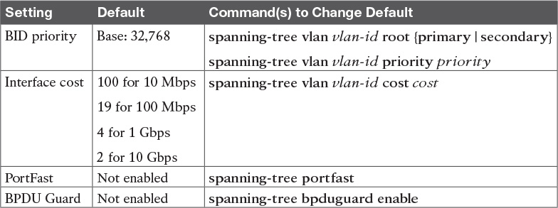
Next, the configuration section shows how to examine the operation of STP in a simple network, along with how to change these optional settings.
Verifying STP Operation
Before taking a look at how to change the configuration, first consider a few STP verification commands. Looking at these commands first will help reinforce the default STP settings. In particular, the examples in this section use the network shown in Figure 3-4.

Example 3-1 begins the discussion with a useful command for STP: the show spanning-tree vlan 10 command. This command identifies the root switch and lists settings on the local switch. Example 3-1 lists the output of this command on both SW1 and SW2, as explained following the example.
Example 3-1 STP Status with Default STP Parameters on SW1 and SW2
SW1# show spanning-tree vlan 10
VLAN0010
Spanning tree enabled protocol ieee
Root ID Priority 32778
Address 1833.9d7b.0e80
This bridge is the root
Hello Time 2 sec Max Age 20 sec Forward Delay 15 sec
Bridge ID Priority 32778 (priority 32768 sys-id-ext 10)
Address 1833.9d7b.0e80
Hello Time 2 sec Max Age 20 sec Forward Delay 15 sec
Aging Time 300 sec
Interface Role Sts Cost Prio.Nbr Type
------------------- ---- --- --------- -------- --------------------------------
Fa0/11 Desg FWD 19 128.11 P2p Edge
Gi0/1 Desg FWD 4 128.25 P2p
Gi0/2 Desg FWD 4 128.26 P2p
SW2# show spanning-tree vlan 10
VLAN0010
Spanning tree enabled protocol ieee
Root ID Priority 32778
Address 1833.9d7b.0e80
Cost 4
Port 26 (GigabitEthernet0/2)
Hello Time 2 sec Max Age 20 sec Forward Delay 15 sec
Bridge ID Priority 32778 (priority 32768 sys-id-ext 10)
Address 1833.9d7b.1380
Hello Time 2 sec Max Age 20 sec Forward Delay 15 sec
Aging Time 300 sec
Interface Role Sts Cost Prio.Nbr Type
------------------- ---- --- --------- -------- --------------------------------
Fa0/12 Desg FWD 19 128.12 P2p
Gi0/1 Desg FWD 4 128.25 P2p
Gi0/2 Root FWD 4 128.26 P2p
Example 3-1 begins with the output of the show spanning-tree vlan 10 command on SW1. This command first lists three major groups of messages: one group of messages about the root switch, followed by another group about the local switch, and ending with interface role and status information. In this case, SW1 lists its own BID as the root, with even a specific statement that “This bridge is the root,” confirming that SW1 is now the root of the VLAN 10 STP topology.
Next, compare the highlighted lines of the same command on SW2 in the lower half of the example. SW2 lists SW1’s BID details as the root; in other words, SW2 agrees that SW1 has won the root election. SW2 does not list the phrase “This bridge is the root.” SW2 then lists its own (different) BID details in the lines after the details about the root’s BID.
The output also confirms a few default values. First, each switch lists the priority part of the BID as a separate number: 32778. This value comes from the default priority of 32768, plus VLAN 10, for a total of 32778. The output also shows the interface cost for some Fast Ethernet and Gigabit Ethernet interfaces, defaulting to 19 and 4, respectively.
Finally, the bottom of the output from the show spanning-tree command lists each interface in the VLAN, including trunks, with the STP port role and port state listed. For instance, on switch SW1, the output lists three interfaces, with a role of Desg for designated port (DP) and a state of FWD for forwarding. SW2 lists three interfaces, two DPs, and one root port, so all three are in an FWD or forwarding state.
Example 3-1 shows a lot of good STP information, but two other commands, shown in Example 3-2, work better for listing BID information in a shorter form. The first, show spanning-tree root, lists the root’s BID for each VLAN. This command also lists other details, like the local switch’s root cost and root port. The other command, show spanning-tree vlan 10 bridge, breaks out the BID into its component parts. In this example, it shows SW2’s priority as the default of 32768, the VLAN ID of 10, and the MAC address.
Example 3-2 Listing Root Switch and Local Switch BIDs on Switch SW2
SW2# show spanning-tree root
Root Hello Max Fwd
Vlan Root ID Cost Time Age Dly Root Port
---------------- -------------------- --------- ----- --- --- ------------
VLAN0001 32769 1833.9d5d.c900 23 2 20 15 Gi0/1
VLAN0010 32778 1833.9d7b.0e80 4 2 20 15 Gi0/2
VLAN0020 32788 1833.9d7b.0e80 4 2 20 15 Gi0/2
VLAN0030 32798 1833.9d7b.0e80 4 2 20 15 Gi0/2
VLAN0040 32808 1833.9d7b.0e80 4 2 20 15 Gi0/2
SW2# show spanning-tree vlan 10 bridge
Hello Max Fwd
Vlan Bridge ID Time Age Dly Protocol
---------------- --------------------------------- ----- --- --- --------
VLAN0010 32778 (32768, 10) 1833.9d7b.1380 2 20 15 ieee
Note that both the commands in Example 3-2 have a VLAN option: show spanning-tree [vlan x] root and show spanning-tree [vlan x] bridge. Without the VLAN listed, each command lists one line per VLAN; with the VLAN, the output lists the same information, but just for that one VLAN.
Configuring STP Port Costs
Changing the STP port costs requires a simple interface subcommand: spanning-tree [vlan x] cost x. To show how it works, consider the following example, which changes what happens in the network shown in Figure 3-4.
Back in Figure 3-4, with default settings, SW1 became root, and SW3 blocked on its G0/2 interface. A brief scan of the figure, based on the default STP cost of 4 for Gigabit interfaces, shows that SW3 should have found a cost 4 path and a cost 8 path to reach the root, as shown in Figure 3-5.
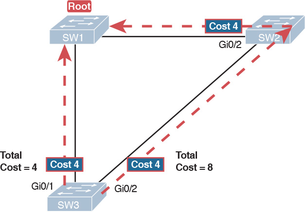
To show the effects of changing the port cost, the next example shows a change to SW3’s configuration, setting its G0/1 port cost higher so that the better path to the root goes out SW3’s G0/2 port instead. Example 3-3 also shows several other interesting effects.
Example 3-3 Manipulating STP Port Cost and Watching the Transition to Forwarding State
SW3# debug spanning-tree events
Spanning Tree event debugging is on
SW3# configure terminal
Enter configuration commands, one per line. End with CNTL/Z.
SW3(config)# interface gigabitethernet0/1
SW3(config-if)# spanning-tree vlan 10 cost 30
SW3(config-if)# ^Z
SW3#
*Mar 11 06:28:00.860: STP: VLAN0010 new root port Gi0/2, cost 8
*Mar 11 06:28:00.860: STP: VLAN0010 Gi0/2 -> listening
*Mar 11 06:28:00.860: STP: VLAN0010 sent Topology Change Notice on Gi0/2
*Mar 11 06:28:00.860: STP[10]: Generating TC trap for port GigabitEthernet0/1
*Mar 11 06:28:00.860: STP: VLAN0010 Gi0/1 -> blocking
*Mar 11 06:28:15.867: STP: VLAN0010 Gi0/2 -> learning
*Mar 11 06:28:30.874: STP[10]: Generating TC trap for port GigabitEthernet0/2
*Mar 11 06:28:30.874: STP: VLAN0010 sent Topology Change Notice on Gi0/2
*Mar 11 06:28:30.874: STP: VLAN0010 Gi0/2 -> forwarding
This example starts with the debug spanning-tree events command on SW3. This command tells the switch to issue debug log messages whenever STP performs changes to an interface’s role or state. These messages show up in the example as a result of the configuration.
Next, the example shows the configuration to change SW3’s port cost, in VLAN 10, to 30, with the spanning-tree vlan 10 cost 30 interface subcommand. Based on the figure, the root cost through SW3’s G0/1 will now be 30 instead of 4. As a result, SW3’s best cost to reach the root is cost 8, with SW3’s G0/2 as its root port.
The debug messages tell us what STP on SW3 is thinking behind the scenes, with timestamps. Note that the first five debug messages, displayed immediately after the user exited configuration mode in this case, all happen at the same time (down to the same millisecond). Notably, G0/1, which had been forwarding, immediately moves to a blocking state. Interface G0/2, which had been blocking, does not go to a forwarding state, instead moving to a listening state (at least, according to this message).
Now look for the debug message that lists G0/2 transitioning to learning state, and then the next one that shows it finally reaching forwarding state. How long between the messages? In each case, the message’s timestamps show that 15 seconds passed. In this experiment, the switches used a default setting of forward delay (15 seconds). So, these debug messages confirm the steps that STP takes to transition an interface from blocking to forwarding state.
If you did not happen to enable a debug when configuring the cost, using show commands later can confirm the same choice by SW3, to now use its G0/2 port as its RP. Example 3-4 shows the new STP port cost setting on SW3, along with the new root port and root cost, using the show spanning-tree vlan 10 command. Note that G0/2 is now listed as the root port. The top of the output lists SW3’s root cost as 8, matching the analysis shown in Figure 3-5.
Example 3-4 New STP Status and Settings on SW3
SW3# show spanning-tree vlan 10
VLAN0010
Spanning tree enabled protocol ieee
Root ID Priority 32778
Address 1833.9d7b.0e80
Cost 8
Port 26 (GigabitEthernet0/2)
Hello Time 2 sec Max Age 20 sec Forward Delay 15 sec
Bridge ID Priority 32778 (priority 32768 sys-id-ext 10)
Address f47f.35cb.d780
Hello Time 2 sec Max Age 20 sec Forward Delay 15 sec
Aging Time 300 sec
Interface Role Sts Cost Prio.Nbr Type
------------------- ---- --- --------- -------- --------------------------------
Fa0/23 Desg FWD 19 128.23 P2p
Gi0/1 Altn BLK 30 128.25 P2p
Gi0/2 Root FWD 4 128.26 P2p
Configuring Priority to Influence the Root Election
The other big STP configuration option is to influence the root election by changing the priority of a switch. The priority can be set explicitly with the spanning-tree vlan vlan-id priority value global configuration command, which sets the base priority of the switch. (This is the command that requires a parameter of a multiple of 4096.)
However, Cisco gives us a better configuration option than configuring a specific priority value. In most designs, the network engineers pick two switches to be root: one to be root if all switches are up, and another to take over if the first switch fails. Switch IOS supports this idea with the spanning-tree vlan vlan-id root primary and spanning-tree vlan vlan-id root secondary commands.
The spanning-tree vlan vlan-id root primary command tells the switch to set its priority low enough to become root right now. The switch looks at the current root in that VLAN, and at the root’s priority. Then the local switch chooses a priority value that causes the local switch to take over as root.
Remembering that Cisco switches use a default base priority of 32,768, this command chooses the base priority as follows:

![]() If the current root has a base priority higher than 24,576, the local switch uses a base priority of 24,576.
If the current root has a base priority higher than 24,576, the local switch uses a base priority of 24,576.
![]() If the current root’s base priority is 24,576 or lower, the local switch sets its base priority to the highest multiple of 4096 that still results in the local switch becoming root.
If the current root’s base priority is 24,576 or lower, the local switch sets its base priority to the highest multiple of 4096 that still results in the local switch becoming root.
For the switch intended to take over as the root if the first switch fails, use the spanning-tree vlan vlan-id root secondary command. This command is much like the spanning-tree vlan vlan-id root primary command, but with a priority value worse than the primary switch but better than all the other switches. This command sets the switch’s base priority to 28,672 regardless of the current root’s current priority value.
For example, in Figures 3-4 and 3-5, SW1 was the root switch, and as shown in various commands, all three switches defaulted to use a base priority of 32,768. Example 3-5 shows a configuration that makes SW2 the primary root, and SW1 the secondary, just to show the role move from one to the other. These commands result in SW2 having a base priority of 24,576, and SW1 having a base priority of 28,672.
Example 3-5 Making SW2 Become Root Primary, and SW1 Root Secondary
! First, on SW2:
SW2# configure terminal
Enter configuration commands, one per line. End with CNTL/Z.
SW2(config)# spanning-tree vlan 10 root primary
SW2(config)# ^Z
! Next, SW1 is configured to back-up SW1
SW1# configure terminal
Enter configuration commands, one per line. End with CNTL/Z.
SW1(config)# spanning-tree vlan 10 root secondary
SW1(config)# ^Z
SW1#
! The next command shows the local switch's BID (SW1)
SW1# show spanning-tree vlan 10 bridge
Hello Max Fwd
Vlan Bridge ID Time Age Dly Protocol
---------------- --------------------------------- ----- --- --- --------
VLAN0010 28682 (28672, 10) 1833.9d7b.0e80 2 20 15 ieee
! The next command shows the root's BID (SW2)
SW1# show spanning-tree vlan 10 root
Root Hello Max Fwd
Vlan Root ID Cost Time Age Dly Root Port
---------------- -------------------- --------- ----- --- --- ------------
VLAN0010 24586 1833.9d7b.1380 4 2 20 15 Gi0/1
The output of the two show commands clearly points out the resulting priority values on each switch. First, the show spanning-tree bridge command lists the local switch’s BID information, while the show spanning-tree root command lists the root’s BID, plus the local switch’s root cost and root port (assuming it is not the root switch). So, SW1 lists its own BID, with priority 28,682 (base 28,672, with VLAN 10) with the show spanning-tree bridge command. Still on SW1, the output lists the root’s priority as 24,586 in VLAN 10, implied as base 24,576 plus 10 for VLAN 10, with the show spanning-tree root command.
Note that alternatively you could have configured the priority settings specifically. SW1 could have used the spanning-tree vlan 10 priority 28672 command, with SW2 using the spanning-tree vlan 10 priority 24576 command. In this particular case, both options would result in the same STP operation.
Implementing Optional STP Features
This just-completed first major section of the chapter showed examples that used PVST+ only, assuming a default global command of spanning-tree mode pvst. At the same time, all the configuration commands shown in that first section, commands that influence STP operation, would influence both traditional STP and RSTP operation.
This section, the second of three major sections in this chapter, now moves on to discuss some useful but optional features that make both STP and RSTP work even better.
Configuring PortFast and BPDU Guard
You can easily configure the PortFast and BPDU Guard features on any interface, but with two different configuration options. One option works best when you want to enable these features only on a few ports, and the other works best when you want to enable these features on most every access port.
First, to enable the features on just one port at a time, use the spanning-tree portfast and the spanning-tree bpduguard enable interface subcommands. Example 3-6 shows an example of the process, with SW3’s F0/4 interface enabling both features. (Also, note the long warning message IOS lists when enabling PortFast; using PortFast on a port connected to other switches can indeed cause serious problems.)
Example 3-6 Enabling PortFast and BPDU Guard on One Interface
SW3# configure terminal
Enter configuration commands, one per line. End with CNTL/Z.
SW3(config)# interface fastEthernet 0/4
SW3(config-if)# spanning-tree portfast
%Warning: portfast should only be enabled on ports connected to a single
host. Connecting hubs, concentrators, switches, bridges, etc... to this
interface when portfast is enabled, can cause temporary bridging loops.
Use with CAUTION
%Portfast has been configured on FastEthernet0/4 but will only
have effect when the interface is in a non-trunking mode.
SW3(config-if)# spanning-tree bpduguard ?
disable Disable BPDU guard for this interface
enable Enable BPDU guard for this interface
SW3(config-if)# spanning-tree bpduguard enable
SW3(config-if)# ^Z
SW3#
Example 3-7 shows some brief information about the interface configuration of both PortFast and BPDU Guard. Of course, the show running-config command (not shown) would confirm the configuration commands from Example 3-6. The show spanning-tree interface fastethernet0/4 portfast command in Example 3-7 lists the PortFast status of the interface; note that the status value of enabled is displayed only if PortFast is configured and the interface is up. The show spanning-tree interface detail command then shows a line near the end of the output that states that PortFast and BPDU Guard are enabled. Note that this command would not list those two highlighted lines of output if these two features were not enabled.
Example 3-7 Verifying PortFast and BPDU Guard Configuration
SW3# show spanning-tree interface fastethernet0/4 portfast
VLAN0104 enabled
SW11# show spanning-tree interface F0/4 detail
Port 4 (FastEthernet0/4) of VLAN0001 is designated forwarding
Port path cost 19, Port priority 128, Port Identifier 128.4.
Designated root has priority 32769, address bcc4.938b.a180
Designated bridge has priority 32769, address bcc4.938b.e500
Designated port id is 128.4, designated path cost 19
Timers: message age 0, forward delay 0, hold 0
Number of transitions to forwarding state: 1
The port is in the portfast mode
Link type is point-to-point by default
Bpdu guard is enabled
BPDU: sent 1721, received 0
PortFast and BPDU Guard are disabled by default on all interfaces, and to use them, each interface requires interface subcommands like those in Example 3-6. Alternately, for both features, you can enable the feature globally. Then, for interfaces for which the feature should be disabled, you can use another interface subcommand to disable the feature.
The ability to change the global default for these features reduces the number of interface subcommands required. For instance, on an access layer switch with 48 access ports and two uplinks, you probably want to enable both PortFast and BPDU Guard on all 48 access ports. Rather than requiring the interface subcommands on all 48 of those ports, enable the features globally, and then disable them on the uplink ports.
Table 3-3 summarizes the commands to enable and disable both PortFast and BPDU Guard, both globally and per interface. For instance, the global command spanning-tree portfast default changes the default so that all interfaces use PortFast, unless a port also has the spanning-tree portfast disable interface subcommand configured.

Example 3-8 shows another new command, show spanning-tree summary. This command shows the current global settings for several STP parameters, including the PortFast and BPDU Guard features. This output was gathered on a switch that had enabled both PortFast and BPDU Guard globally.
Example 3-8 Displaying Status of Global Settings for PortFast and BPDU Guard
SW1# show spanning-tree summary
Switch is in pvst mode
Root bridge for: none
EtherChannel misconfig guard is enabled
Extended system ID is enabled
Portfast Default is enabled
PortFast BPDU Guard Default is enabled
Portfast BPDU Filter Default is disabled
Loopguard Default is disabled
UplinkFast is disabled
BackboneFast is disabled
Configured Pathcost method used is short
Name Blocking Listening Learning Forwarding STP Active
---------------------- -------- --------- -------- ---------- ----------
VLAN0001 3 0 0 2 5
---------------------- -------- --------- -------- ---------- ----------
1 vlan 3 0 0 2 5
Configuring EtherChannel
As introduced back in Chapter 2, two neighboring switches can treat multiple parallel links between each other as a single logical link called an EtherChannel. STP operates on the EtherChannel, instead of the individual physical links, so that STP either forwards or blocks on the entire logical EtherChannel for a given VLAN. As a result, a switch in a forwarding state can then load balance traffic over all the physical links in the EtherChannel. Without EtherChannel, only one of the parallel links between two switches would be allowed to forward traffic, with the rest of the links blocked by STP.
Note
All references to EtherChannel in this Chapter refer to Layer 2 EtherChannels, and not to Layer 3 EtherChannels (as discussed in Chapter 19, “IPv4 Routing in the LAN”).
EtherChannel may be one of the most challenging switch features to make work. First, the configuration has several options, so you have to remember the details of which options work together. Second, the switches also require a variety of other interface settings to match among all the links in the channel, so you have to know those settings as well.
This section focuses on the correct EtherChannel configuration. Chapter 4’s section “Troubleshooting Layer 2 EtherChannel” looks at many of the potential problems with EtherChannel, including all those other configuration settings that a switch checks before allowing the EtherChannel to work.
Configuring a Manual EtherChannel
The simplest way to configure an EtherChannel is to add the correct channel-group configuration command to each physical interface, on each switch, all with the on keyword. The on keyword tells the switches to place a physical interface into an EtherChannel.
Before getting into the configuration and verification, however, you need to start using three terms as synonyms: EtherChannel, PortChannel, and Channel-group. Oddly, IOS uses the channel-group configuration command, but then to display its status, IOS uses the show etherchannel command. Then, the output of this show command refers to neither an “EtherChannel” nor a “Channel-group,” instead using the term “PortChannel.” So, pay close attention to these three terms in the example.
To configure an EtherChannel manually, follow these steps:
Step 1. Add the channel-group number mode on command in interface configuration mode under each physical interface that should be in the channel to add it to the channel.
Step 2. Use the same number for all commands on the same switch, but the channel-group number on the neighboring switch can differ.
Example 3-9 shows a simple example, with two links between switches SW1 and SW2, as shown in Figure 3-6. The configuration shows SW1’s two interfaces placed into channel-group 1, with two show commands to follow.

Example 3-9 Configuring and Monitoring EtherChannel
SW1# configure terminal
Enter configuration commands, one per line. End with CNTL/Z.
SW1(config)# interface fa 0/14
SW1(config-if)# channel-group 1 mode on
SW1(config)# interface fa 0/15
SW1(config-if)# channel-group 1 mode on
SW1(config-if)# ^Z
SW1# show spanning-tree vlan 3
VLAN0003
Spanning tree enabled protocol ieee
Root ID Priority 28675
Address 0019.e859.5380
Cost 12
Port 72 (Port-channel1)
Hello Time 2 sec Max Age 20 sec Forward Delay 15 sec
Bridge ID Priority 28675 (priority 28672 sys-id-ext 3)
Address 0019.e86a.6f80
Hello Time 2 sec Max Age 20 sec Forward Delay 15 sec
Aging Time 300
Interface Role Sts Cost Prio.Nbr Type
---------------- ---- --- --------- -------- --------------------------------
Po1 Root FWD 12 128.64 P2p Peer(STP)
SW1# show etherchannel 1 summary
Flags: D - down P - bundled in port-channel
I - stand-alone s - suspended
H - Hot-standby (LACP only)
R - Layer3 S - Layer2
U - in use f - failed to allocate aggregator
M - not in use, minimum links not met
u - unsuitable for bundling
w - waiting to be aggregated
d - default port
Number of channel-groups in use: 1
Number of aggregators: 1
Group Port-channel Protocol Ports
------+-------------+-----------+-----------------------------------------------
1 Po1(SU) - Fa0/14(P) Fa0/15(P)
Take a few moments to look at the output in the two show commands in the example, as well. First, the show spanning-tree command lists Po1, short for PortChannel1, as an interface. This interface exists because of the channel-group commands using the 1 parameter. STP no longer operates on physical interfaces F0/14 and F0/15, instead operating on the PortChannel1 interface, so only that interface is listed in the output.
Next, note the output of the show etherchannel 1 summary command. It lists as a heading “Port-channel,” with Po1 below it. It also lists both F0/14 and F0/15 in the list of ports, with a (P) beside each. Per the legend, the P means that the ports are bundled in the port channel, which is a code that means these ports have passed all the configuration checks and are valid to be included in the channel.
Note
Cisco uses the term EtherChannel to refer to the concepts discussed in this section. To refer to the item configured in the switch, Cisco instead uses the term port channel, with the command keyword port-channel. For the purposes of understanding the technology, you may treat these terms as synonyms. However, it helps to pay close attention to the use of the terms port channel and EtherChannel as you work through the examples in this section, because IOS uses both.
Configuring Dynamic EtherChannels
Cisco switches support two different protocols that allow the switches to negotiate whether a particular link becomes part of an EtherChannel or not. Basically, the configuration enables the protocol for a particular channel-group number. At that point, the switch can use the protocol to send messages to/from the neighboring switch and discover whether their configuration settings pass all checks. If a given physical link passes, the link is added to the EtherChannel and used; if not, it is placed in a down state, and not used, until the configuration inconsistency can be resolved.
Cisco switches support the Cisco-proprietary Port Aggregation Protocol (PAgP) and the IEEE standard Link Aggregation Control Protocol (LACP), based on IEEE standard 802.3ad. Although differences exist between the two, to the depth discussed here, they both accomplish the same task: negotiate so that only links that pass the configuration checks are actually used in an EtherChannel.
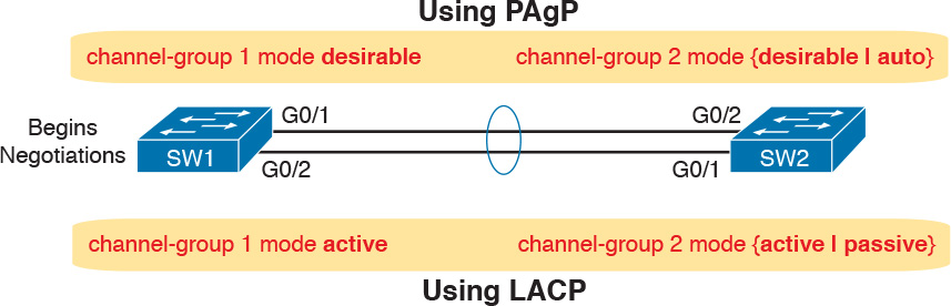
To configure either protocol, a switch uses the channel-group configuration commands on each switch, but with a keyword that either means “use this protocol and begin negotiations” or “use this protocol and wait for the other switch to begin negotiations.” As shown in Figure 3-7, the desirable and auto keywords enable PAgP, and the active and passive keywords enable LACP. With these options, at least one side has to begin the negotiations. In other words, with PAgP, at least one of the two sides must use desirable, and with LACP, at least one of the two sides must use active.
Note
Do not use the on parameter on one end, and either auto or desirable (or for LACP, active or passive) on the neighboring switch. The on option uses neither PAgP nor LACP, so a configuration that uses on, with PAgP or LACP options on the other end, would prevent the EtherChannel from working.
For example, in the design shown in Figure 3-7, imagine both physical interfaces on both switches were configured with the channel-group 2 mode desirable interface subcommand. As a result, the two switches would negotiate and create an EtherChannel. Example 3-10 shows the verification of that configuration, with the command show etherchannel 2 port-channel. This command confirms the protocol in use (PAgP, because the desirable keyword was configured), and the list of interfaces in the channel.
Example 3-10 EtherChannel Verification: PAgP Desirable Mode
SW1# show etherchannel 2 port-channel
Port-channels in the group:
---------------------------
Port-channel: Po2
------------
Age of the Port-channel = 0d:00h:04m:04s
Logical slot/port = 16/1 Number of ports = 2
GC = 0x00020001 HotStandBy port = null
Port state = Port-channel Ag-Inuse
Protocol = PAgP
Port security = Disabled
Ports in the Port-channel:
Index Load Port EC state No of bits
------+------+------+------------------+-----------
0 00 Gi0/1 Desirable-Sl 0
0 00 Gi0/2 Desirable-Sl 0
Time since last port bundled: 0d:00h:03m:57s Gi0/2
Implementing RSTP
All you have to do to migrate from STP to RSTP is to configure the spanning-tree mode rapid-pvst global command on all the switches. However, for exam preparation, it helps to work through the various show commands, particularly to prepare for Simlet questions. Those questions can ask you to interpret show command output without allowing you to look at the configuration, and the output of show commands when using STP versus RSTP is very similar.
This third and final major section of this chapter focuses on pointing out the similarities and differences between STP and RSTP as seen in Catalyst switch configuration and verification commands. This section explains the configuration and verification of RSTP, with emphasis on how to identify RSTP features.
Identifying the STP Mode on a Catalyst Switch
Cisco Catalyst switches operate in some STP mode as defined by the spanning-tree mode global configuration command. Based on this command’s setting, the switch is using either 802.1D STP or 802.1w RSTP, as noted in Table 3-4.

To determine whether a Cisco Catalyst switch uses RSTP, you can look for two types of information. First, you can look at the configuration, as noted in the left column of Table 3-4. Also, some show commands list the STP protocol as a reference to the configuration of the spanning-tree mode global configuration command. A protocol of rstp or mst refers to one of the modes that uses RSTP, and a protocol of ieee refers to the mode that happens to use STP.
Before looking at an example of the output, review the topology in Figure 3-8. The remaining RSTP examples in this chapter use this topology. In the RSTP examples in this chapter, SW1 will become root, and SW3 will block on one port (G0/2), as shown.

The first example focuses on VLAN 10, with all switches using 802.1D STP and the default setting of spanning-tree mode pvst. This setting creates an instance of STP per VLAN (which is the per-VLAN part of the name) and uses 802.1D STP. Each switch places the port connected to the PC into VLAN 10 and enables both PortFast and BPDU Guard. Example 3-11 shows a sample configuration from switch SW3, with identical interface subcommands configured on SW1’s F0/11 and SW2’s F0/12 ports, respectively.
Example 3-11 Sample Configuration from Switch SW3
SW3# show running-config interface Fastethernet 0/13
Building configuration...
Current configuration : 117 bytes
!
interface FastEthernet0/13
switchport access vlan 10
spanning-tree portfast
spanning-tree bpduguard enable
end
At this point, the three switches use 802.1D STP because all use the default PVST mode. Example 3-12 shows the evidence of STP’s work, with only subtle and indirect clues that STP happens to be in use.
Example 3-12 Output That Confirms the Use of 802.1D STP on Switch SW3
SW3# show spanning-tree vlan 10
VLAN0010
Spanning tree enabled protocol ieee
Root ID Priority 32778
Address 1833.9d7b.0e80
Cost 4
Port 25 (GigabitEthernet0/1)
Hello Time 2 sec Max Age 20 sec Forward Delay 15 sec
Bridge ID Priority 32778 (priority 32768 sys-id-ext 10)
Address f47f.35cb.d780
Hello Time 2 sec Max Age 20 sec Forward Delay 15 sec
Aging Time 300 sec
Interface Role Sts Cost Prio.Nbr Type
------------------- ---- --- --------- -------- --------------------------------
Fa0/13 Desg FWD 19 128.13 P2p Edge
Gi0/1 Root FWD 4 128.25 P2p
Gi0/2 Altn BLK 4 128.26 P2p
SW3# show spanning-tree vlan 10 bridge
Hello Max Fwd
Vlan Bridge ID Time Age Dly Protocol
---------------- --------------------------------- ----- --- --- --------
VLAN0010 32778 (32768, 10) f47f.35cb.d780 2 20 15 ieee
The highlighted parts of the example note the references to the STP protocol as ieee, which implies that STP is in use. The term ieee is a reference to the original IEEE 802.1D STP standard.
To migrate this small network to use RSTP, configure the spanning-tree mode rapid-pvst command. This continues the use of per-VLAN spanning-tree instances, but it applies RSTP logic to each STP instance. Example 3-13 shows the output of the same two commands from Example 3-12 after configuring the spanning-tree mode rapid-pvst command on all three switches.
Example 3-13 Output That Confirms the Use of 802.1w RSTP on Switch SW3
SW3# show spanning-tree vlan 10
VLAN0010
Spanning tree enabled protocol rstp
Root ID Priority 32778
Address 1833.9d7b.0e80
Cost 4
Port 25 (GigabitEthernet0/1)
Hello Time 2 sec Max Age 20 sec Forward Delay 15 sec
Bridge ID Priority 32778 (priority 32768 sys-id-ext 10)
Address f47f.35cb.d780
Hello Time 2 sec Max Age 20 sec Forward Delay 15 sec
Aging Time 300 sec
Interface Role Sts Cost Prio.Nbr Type
------------------- ---- --- --------- -------- --------------------------------
Fa0/13 Desg FWD 19 128.13 P2p Edge
Gi0/1 Root FWD 4 128.25 P2p
Gi0/2 Altn BLK 4 128.26 P2p
SW3# show spanning-tree vlan 10 bridge
Hello Max Fwd
Vlan Bridge ID Time Age Dly Protocol
---------------- --------------------------------- ----- --- --- --------
VLAN0010 32778 (32768, 10) f47f.35cb.d780 2 20 15 rstp
Pay close attention to the differences between the 802.1D STP output in Example 3-12 and the 802.1w RSTP output in Example 3-13. Literally, the only difference is rstp instead of ieee in one place in the output of each of the two commands listed. In this case, rstp refers to the configuration of the spanning-tree mode rapid-pvst global config command, which implied the use of RSTP.
RSTP Port Roles
RSTP adds two port roles to STP: the alternate port and the backup port. Example 3-14 repeats an excerpt from the show spanning-tree vlan 10 command on switch SW3 to show an example of the alternate port role. SW3 (as shown earlier in Figure 3-8) is not the root switch, with G0/1 as its root port and G0/2 as an alternate port.
Example 3-14 Output Confirming SW3’s Root Port and Alternate Port Roles
SW3# show spanning-tree vlan 10
! Lines omitted for brevity
Interface Role Sts Cost Prio.Nbr Type
------------------- ---- --- --------- -------- --------------------------------
Fa0/13 Desg FWD 19 128.13 P2p Edge
Gi0/1 Root FWD 4 128.25 P2p
Gi0/2 Altn BLK 4 128.26 P2p
The good news is that the output clearly lists which port is the root port (Gi0/1) and which port is the alternate root port (Gi0/2). The only trick is to know that Altn is a shortened version of the word alternate.
Pay close attention to this short description of an oddity about the STP and RSTP output on Catalyst switches! Cisco Catalyst switches often show the alternate and backup ports in output even when using STP and not RSTP. The alternate and backup port concepts are RSTP concepts. The switches only converge faster using these concepts when using RSTP. But show command output, when using STP and not RSTP, happens to identify what would be the alternate and backup ports if RSTP were used.
Why might you care about such trivia? Seeing output that lists an RSTP alternate port does not confirm that the switch is using RSTP. So, do not make that assumption on the exam. To confirm that a switch uses RSTP, you must look at the configuration of the spanning-tree mode command, or look for the protocol as summarized back in Table 3-4.
For instance, just compare the output of Example 3-12 and Example 3-14. Example 3-12 shows output for this same SW3, with the same parameters, except that all switches used PVST mode, meaning all the switches used STP. Example 3-12’s output (based on STP) lists SW3’s G0/2 as Altn, meaning alternate, even though the alternate port concept is not an STP concept, but an RSTP concept.
RSTP Port States
RSTP added one new port state compared to STP, discarding, using it as a replacement for the STP port states of disabled and blocking. You might think that after you configure a switch to use RSTP rather than STP, instead of seeing ports in a blocking state, you would now see the discarding state. However, the Cisco Catalyst switch output basically ignores the new term discarding, continuing to use the old term blocking instead.
For example, scan back to the most recent RSTP example (Example 3-14), to the line for SW3’s port G0/2. Then look for the column with heading STS, which refers to the status or state. The output shows G0/2 is listed as BLK, or blocking. In theory, because SW3 uses RSTP, the port state ought to be discarding, but the switch IOS continues to use the older notation of BLK for blocking.
Just as one more bit of evidence, the command show spanning-tree vlan 10 interface gigabitethernet0/2 state lists the STP or RSTP port state with the state fully spelled out. Example 3-15 shows this command, taken from SW3, for interface G0/2. Note the fully spelled-out blocking term instead of the RSTP term discarding.
Example 3-15 SW3, an RSTP Switch, Continues to Use the Old Blocking Term
SW3# show spanning-tree vlan 10 interface gigabitEthernet 0/2 state
VLAN0010 blocking
RSTP Port Types
Cisco Catalyst switches determine the RSTP port type based on two port settings: the current duplex (full or half) and whether the PortFast feature is enabled. First, full duplex tells the switch to use port type point-to-point, with half duplex telling the switch to use port type shared. Enabling PortFast tells the switch to treat the port as an edge port. Table 3-5 summarizes the combinations.

You can easily find the RSTP port types in the output of several commands, including the same show spanning-tree command in Example 3-16. Example 3-16 lists output from switch SW2, with a hub added off SW2’s F0/18 port (not shown in Figure 3-8). The hub was added so that the output in Example 3-16 lists a shared port (noted as Shr) to go along with the point-to-point ports (noted as P2p).
SW2# show spanning-tree vlan 10
VLAN0010
Spanning tree enabled protocol rstp
Root ID Priority 32778
Address 1833.9d7b.0e80
Cost 4
Port 26 (GigabitEthernet0/2)
Hello Time 2 sec Max Age 20 sec Forward Delay 15 sec
Bridge ID Priority 32778 (priority 32768 sys-id-ext 10)
Address 1833.9d7b.1380
Hello Time 2 sec Max Age 20 sec Forward Delay 15 sec
Aging Time 300 sec
Interface Role Sts Cost Prio.Nbr Type
------------------- ---- --- --------- -------- --------------------------------
Fa0/12 Desg FWD 19 128.12 P2p Edge
Fa0/18 Desg FWD 19 128.18 Shr
Gi0/1 Desg FWD 4 128.25 P2p
Gi0/2 Root FWD 4 128.26 P2p
For exam prep, again note an odd fact about the highlighted output in Example 3-16: The port type details appear in the output when using both STP and RSTP. For example, refer to Example 3-12 again, which shows output from SW3 when using STP (when configured for PVST mode). The Type column also identifies point-to-point and edge interfaces.
Chapter Review
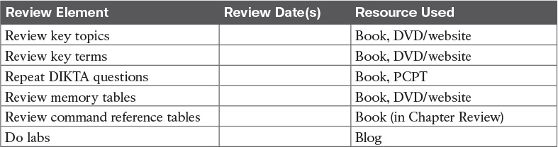
One key to doing well on the exams is to perform repetitive spaced review sessions. Review this chapter’s material using either the tools in the book, DVD, or interactive tools for the same material found on the book’s companion website. Refer to the “Your Study Plan” element for more details. Table 3-6 outlines the key review elements and where you can find them. To better track your study progress, record when you completed these activities in the second column.
Review All the Key Topics

Key Terms You Should Know
Command References
Tables 3-8 and 3-9 list configuration and verification commands used in this chapter. As an easy review exercise, cover the left column in a table, read the right column, and try to recall the command without looking. Then repeat the exercise, covering the right column, and try to recall what the command does.


Table 3-9 Chapter 3 EXEC Command Reference