
Chapter 14. Private WANs with Ethernet and MPLS
This chapter covers the following exam topics:
3.0 WAN Technologies
3.4 Describe WAN topology options
3.4.a Point-to-point
3.4.b Hub and spoke
3.4.c Full mesh
3.5 Describe WAN access connectivity options
3.5.a MPLS
3.5.b MetroEthernet
This chapter details the concepts behind two types of private WAN service: Metro Ethernet (MetroE) and Multiprotocol Label Switching (MPLS). As usual for this book’s discussion of WAN services, the service is viewed mostly from the perspective of the enterprise, as the customer of some WAN service provider (SP). That means the discussion focuses on what the enterprise receives from the service, rather than how the service provider implements the service inside its network. (Note that Cisco’s Service Provider certification track explores the details of how an SP implements its network.)
This chapter reflects probably the biggest single change to what Cisco includes for WAN topics in the CCNA R&S certification for the entire history of the certification. Cisco introduced the CCNA certification back in 1998 (now called CCNA Routing and Switching). At that time, Frame Relay was the dominant WAN technology, and leased lines, an older technology, were still used. Cisco has included both leased lines and Frame Relay in CCNA R&S for the certification’s entire history until the release of new exams in 2016, with the CCNA 200-125 exam (which is sometimes referenced by Cisco as CCNA v3.0). Frame Relay is not mentioned at all in the current exam topics, although serial links do still get a brief mention because of some related data link protocols.
Cisco replaces Frame Relay in the exam topics with two notable WAN technologies more commonly used today: Metro Ethernet and MPLS. For perspective, Figure 14-1 shows a timeline of approximately when some of the more common private WAN services entered the marketplace.

This chapter begins with Metro Ethernet in the first major section, followed by MPLS VPNs in the second, even though MPLS VPNs came first historically. Introducing Metro Ethernet first should be easier to learn, given the many similarities between using Ethernet in the LAN and using Ethernet in the WAN.
For those of you interested in reading about the old Frame Relay topics, the previous edition’s two chapters about Frame Relay are included with this book, as Appendixes H and I.
“Do I Know This Already?” Quiz
Take the quiz (either here, or use the PCPT software) if you want to use the score to help you decide how much time to spend on this chapter. The answers are at the bottom of the page following the quiz, and the explanations are in DVD Appendix C and in the PCPT software.

1. Which of the following topology terms most closely describe the topology created by a Metro Ethernet Tree (E-Tree) service? (Choose two answers.)
a. Full mesh
b. Partial mesh
c. Hub and Spoke
d. Point-to-point
2. Which of the following is the most likely technology used for an access link to a Metro Ethernet service?
a. 100Base-LX10
b. High-speed TDM (for example, T3, E3)
c. MPLS
d. 100Base-T
3. An enterprise uses a Metro Ethernet WAN with an Ethernet LAN (E-LAN) service, with the company headquarters plus ten remote sites connected to the service. The enterprise uses EIGRP at all sites, with one router connected to the service from each site. Which of the following are true about the Layer 3 details most likely used with this service and design? (Choose two answers.)
a. The WAN uses one IP subnet.
b. The WAN uses ten or more IP subnets.
c. A remote site router would have one EIGRP neighbor.
d. A remote site router would have ten EIGRP neighbors.
4. An enterprise uses an MPLS Layer 3 VPN with the company headquarters connected plus ten remote sites connected to the service. The enterprise uses EIGRP at all sites, with one router connected to the service from each site. Which of the following are true about the Layer 3 details most likely used with this service and design? (Choose two answers.)
a. The WAN uses one IP subnet.
b. The WAN uses ten or more IP subnets.
c. A remote site router would have one EIGRP neighbor.
d. A remote site router would have ten or more EIGRP neighbors.
5. Which of the following answers is most accurate about access link options for an MPLS network?
a. Uses only TDM (T1, T3, E1, E3, etc.)
b. Uses only Ethernet
c. Uses only DSL and cable
d. Uses a wide variety of Layer 1 and Layer 2 networking technologies
6. An enterprise connects 20 sites into an MPLS VPN WAN. The enterprise uses OSPF for IPv4 routes at all sites. Consider the OSPF area design options, and the PE-CE links. Which of the following answers is most accurate about OSPF areas and the PE-CE links?
a. The PE-CE link may or may not be chosen to be in backbone area 0.
b. The PE-CE link must not be in the backbone area 0.
c. The PE-CE link must be in the backbone area 0.
d. The PE-CE link will not be in any OSPF area.
Answers to the “Do I Know This Already?” quiz:
1 B, C 2 A 3 A, D 4 B, C 5 D 6 A
Foundation Topics
Metro Ethernet
Metro Ethernet (MetroE) includes a variety of WAN services with some common features. Each MetroE service uses Ethernet physical links to connect the customer’s device to the service provider’s device. Second, the service is a Layer 2 service in that the WAN provider forwards Ethernet frames from one customer device to another.
To begin the conversation with a basic view, Metro Ethernet acts much as if the WAN service were created by one Ethernet switch, as shown in Figure 14-2. The figure shows four sites in the same company, each with a router. Each router is connected to the WAN service with an Ethernet link of some kind; those Ethernet links typically use one of the fiber Ethernet standards due to the distances involved. From the customer’s perspective (that is, from the perspective of the enterprise that is the customer of the WAN SP), the WAN service acts like a LAN switch in that it forwards Ethernet frames.

Note
Throughout this chapter, the word customer refers to the customer of the service provider; that is, the enterprise that is purchasing the WAN service.
Although the main concept makes a Metro Ethernet service act like a big LAN switch, there are many options, and you should understand the basics of each. Additionally, many customers connect to a Metro Ethernet service with either routers or Layer 3 switches, which brings up some Layer 3 issues with IP addressing and routing protocols. This section closes with a discussion of the Layer 3 issues.
Metro Ethernet Physical Design and Topology
From an enterprise perspective, to use a Metro Ethernet service, each site needs to connect to the service with (at least) one Ethernet link. There is no need to connect each enterprise router to each other enterprise router directly with a physical link. For instance, in Figure 14-2 in the previous section, each of the four enterprise routers connects to the SP’s MetroE service with one physical Ethernet link, rather than connecting directly to the other enterprise routers.
From the SP perspective, the SP needs to build a network to create the Metro Ethernet service. To keep costs lower the SP puts a device (typically an Ethernet switch) physically near to as many customer sites as possible, in an SP facility called a point of presence (PoP). Those SP switches need to be near enough to many customer locations so that some Ethernet standard supports the distance from the SP’s PoP to each customer site. Figure 14-3 collects some of these terms and ideas together.

Working through the details in the figure, the physical link between the customer and the SP is called an access link or, when using Ethernet specifically, an Ethernet access link. Everything that happens on that link falls within the definition of the user network interface, or UNI. Breaking down the term UNI, the word network refers to the SP’s network, while the SP’s customer (the enterprise) is known as the user of the network.
Focusing on the center of Figure 14-3, the SP’s network remains hidden to a great extent. The SP promises to deliver Ethernet frames across the WAN. To do that, the access links connect to an Ethernet switch. As you can imagine, the switch will look at the Ethernet header’s MAC address fields and at 802.1Q trunking headers for VLAN tags, but the details inside the network remain hidden.
The term carrier Ethernet, meaning Ethernet WAN service provider by a carrier (that is, service provider) is also used instead of Metro Ethernet. Metro Ethernet began as a technology used to create networks in metropolitan areas of cities (generically called metropolitan-area networks, or MANs), so the name Metro Ethernet made more sense. Carrier Ethernet is a better name today, because it is not limited to a single city.
The UNI references a variety of standards, including the fact that any IEEE Ethernet standard can be used for the access link. Table 14-2 lists some of the standards you might expect to see used as Ethernet access links, given their support of longer distances than the standards that use UTP cabling.

Ethernet WAN Services and Topologies
Beyond adding a physical Ethernet connection from each site into the SP’s Metro Ethernet WAN service, the enterprise must choose between several possible variations of MetroE services. Those variations use different topologies that meet different customer needs.
MEF (http://www.mef.net) defines the standards for Metro Ethernet, including the specifications for different kinds of MetroE services. Table 14-3 lists three service types described in this chapter, and their topologies. The next few pages after the table go into more depth about each.

Note
You may see the term Virtual Private Wire Service (VPWS) used for what MEF defines as E-Line service, and Virtual Private LAN Service (VPLS) used for what MEF defines as E-LAN service. You might also see the term Ethernet over MPLS (EoMPLS). All these terms refer to cases in which the SP uses MPLS internally to create what the customer sees as an Ethernet WAN service.
Ethernet Line Service (Point-to-Point)
The Ethernet Line Service, or E-Line, is the simplest of the Metro Ethernet services. The customer connects two sites with access links. Then the MetroE service allows the two customer devices to send Ethernet frames to each other. Figure 14-4 shows an example, with routers as the CPE devices.

As with all MetroE services, the promise made by the service is to deliver Ethernet frames across the service, as if the two customer routers had a rather long crossover cable connected between them. In fact, the E-Line service is the same Ethernet WAN service you have already seen in many examples throughout the ICND1 Cert Guide and in this book. For instance, in this case:
![]() The routers would use physical Ethernet interfaces.
The routers would use physical Ethernet interfaces.
![]() The routers would configure IP addresses in the same subnet as each other.
The routers would configure IP addresses in the same subnet as each other.
![]() Their routing protocols would become neighbors and exchange routes.
Their routing protocols would become neighbors and exchange routes.
The MetroE specifications define the concept of an Ethernet Virtual Connection, or EVC, to define which user (customer) devices can communicate with which. By definition, an E-Line service (as shown in Figure 14-4) creates a point-to-point EVC, meaning that the service allows two endpoints to communicate.
It may be that an enterprise wants to implement a network exactly as shown in Figure 14-4, with two sites and two routers, with MetroE WAN connectivity using an E-Line service. Other variations exist, even other variations using an E-Line.
For example, think of a common enterprise WAN topology with a central site and 100 remote sites. As shown so far, with an E-Line service, the central site router would need 100 Ethernet interfaces to connect to those 100 remote sites. That could be expensive. As an alternative, the enterprise could use the design partially shown in Figure 14-5 (just three remote sites shown). In this case:
![]() The central site router uses a single 10-Gbps access link.
The central site router uses a single 10-Gbps access link.
![]() The central site connects to 100 E-Lines (only three shown).
The central site connects to 100 E-Lines (only three shown).
![]() All the E-Lines send and receive frames over the same access link.
All the E-Lines send and receive frames over the same access link.

Note that this chapter does not get into the configuration details for WAN services. However, designs like Figure 14-5, with multiple E-Line services on a single access link, use 802.1Q trunking, with a different VLAN ID for each E-Line service. As a result, the router configuration can use a typical router configuration with trunking and subinterfaces.
Before moving on to the next MetroE service, note that the customer could use switches instead of routers to connect to the WAN. Historically, enterprise engineers place routers at the edge of a WAN, in part because that device connected to both the WAN and the LAN, and the LAN and WAN used different types of physical interfaces and different data link protocols. As a result of how routing works, routers served as the perfect device to sit at the edge between LAN and WAN (called the WAN edge). With MetroE, the LAN and WAN are both Ethernet, so an Ethernet switch becomes an option.
Ethernet LAN Service (Full Mesh)
Imagine an enterprise needs to connect several sites to a WAN, and the goal is to allow every site to send frames directly to every other site. You could do that with E-Lines, but you would need possibly lots of E-Lines. For instance, to connect three sites with E-Lines so that each site could send frames directly to each other, you only need three E-Lines. But with four, five, and six sites, you would need 6, 10, and 15 E-Lines, respectively. Get up to 20 sites for which all could send frames directly to each other, and you would need 190 E-Lines. (The formula is N(N – 1) / 2.)
The people who created MetroE anticipated the need for designs that allow a full mesh—that is, for each pair of nodes in the service to send frames to each other directly. In fact, allowing all devices to send directly to every other device sounds a lot like an Ethernet LAN, so the MetroE service is called an Ethernet LAN service, or E-LAN.
One E-LAN service allows all devices connected to that service to send Ethernet frames directly to every other device, just as if the Ethernet WAN service were one big Ethernet switch. Figure 14-6 shows a representation of a single E-LAN EVC. In this case, the one EVC connects to four customer sites, creating one E-LAN. Routers R1, R2, R3, and R4 can all send frames directly to each other. They would also all be in the same Layer 3 subnet on the WAN.

An E-LAN service connects the sites in a full mesh. The term full mesh refers to a design that, for a set of devices, creates a direct communication path for each pair. In contrast, a partial mesh refers to a design in which only some of the pairs can communicate directly. Ethernet Tree service (E-Trees), as discussed in the next topic, create a partial mesh design.
Ethernet Tree Service (Hub and Spoke)
The Ethernet Tree service (E-Tree) creates a WAN topology in which the central site device can send Ethernet frames directly to each remote (leaf) site, but the remote (leaf) sites can send only to the central site. Figure 14-7 shows the topology, again with a single EVC. In this case, Router R1 is the root site, and can send to all three remote sites. Routers R2, R3, and R4 can send only to R1.

With an E-Tree, the central site serves as the root of a tree, and each remote site as one of the leaves. The topology goes by many names: partial mesh, hub-and-spoke, and point-to-multipoint. Regardless of the term you use, an E-Tree service creates a service that works well for designs with a central site plus many remote sites.
Layer 3 Design Using Metro Ethernet
Now that you know the basics of the E-Line (point-to-point), E-LAN (full mesh), and E-Tree (point-to-multipoint, hub-and-spoke) services, this next topic reviews some Layer 3 design details when using each of these three services. That is, if the enterprise uses routers or Layer 3 switches as its WAN edge devices, how should the engineer plan for IP addresses and subnets? What is the impact on routing protocols? This section answers those questions.
Note that this section uses routers as the enterprise’s devices, but the concepts apply to Layer 3 switches as well.
Layer 3 Design with E-Line Service
Every E-Line uses a point-to-point topology. As a result, the two routers on the ends of an E-Line need to be in the same subnet. Similarly, when an enterprise uses multiple E-Lines, each should be in a different subnet. As an example, consider Figure 14-8, which shows two E-Lines, both of which connect to Router R1 on the left.

Focusing on the E-Lines, and ignoring the access links for the most part, think of each E-Line as a subnet. Each router needs an IP address in each subnet, and the subnets need to be unique. All the addresses come from the enterprise’s IP address space. Figure 14-9 shows an example of the addresses, subnets, and two OSPF-learned routes in the routing table of R3.

Examine the IP routing table in the lower right of the figure, first focusing on the route to subnet 10.1.1.0/24, which is the LAN subnet off Router R1. R3’s route points to a next-hop router IP address that is R1’s IP address on the Ethernet WAN, specifically the address on the other side of the E-Line that connects R1 and R3. This route should not be a surprise: For R3 to send packets to a subnet connected to R1, R3 sends the packets to R1. Also, it happens to use a subinterface (G0/1.13), which means that the design is using 802.1Q trunking on the link.
Next, look at R3’s route for subnet 10.1.2.0/24, which supports the fact that R3 cannot send packets directly to R2 with the current WAN design. R3 does not have an E-Line that allows R3 to send frames directly to R2. R3 will not become routing protocol neighbors with R2 either. So, R3 will learn its route for subnet 10.1.2.0/24 from R1, with R1’s 10.1.13.1 address as the next-hop address. As a result, when forwarding packets, R3 will forward packets to R1, which will then forward them over the other E-Line to R2.
Layer 3 Design with E-LAN Service
If you connected four routers to one LAN switch, all in the same VLAN, what would you expect for the IP addresses on those routers? And if all four routers used the same routing protocol, which would become neighbors? Typically, with four routers connected to the same switch, on the same VLAN, using the same routing protocol, normally all four routers would have IP addresses in the same subnet, and all would become neighbors.
On an E-LAN service, the same IP addressing design is used, with the same kinds of routing protocol neighbor relationships. Figure 14-10 shows an example that includes subnets and addresses, plus one route as an example. Note that the four routers connected to the E-LAN service in the center all have addresses in subnet 10.1.99.0/24.
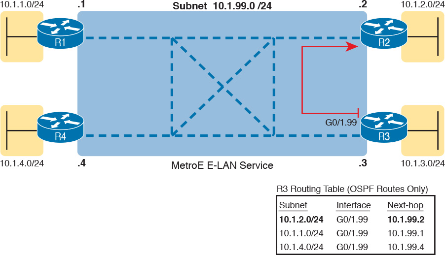
Look at R3’s routing table in the figure, the route from R3 to R2’s LAN subnet (10.1.2.0/24). In this case, R3’s next-hop address is the WAN address on R2 (10.1.99.2), and R3 will send packets (encapsulated in Ethernet frames) directly to R2. Note also that the other two routes in the routing table list the next-hop addresses of R1 (10.1.99.1) and R4 (10.1.99.4).
Layer 3 Design with E-Tree Service
With an E-Tree service, the Layer 3 design again matches the EVC. That is, all the devices using the same single EVC have an address in the same subnet. However, an E-Tree can present some challenges for routing protocols, because of the three services discussed in this chapter, it is the only one in which some of the sites in the same EVC cannot send frames directly to each other.
For example, Figure 14-11 shows one E-Tree service with R1 as the root. Routers R2 and R3, as leaves, cannot send frames directly to each other, and therefore do not form routing protocol neighbor relationships. However, all three connect to the same E-Tree service. As a result:
![]() All three routers have an IP address in the same subnet (10.1.123.0/24).
All three routers have an IP address in the same subnet (10.1.123.0/24).
![]() R1 will form a routing protocol neighbor relationship with both R2 and R3, but R2 will not form a routing protocol neighbor relationship with R3.
R1 will form a routing protocol neighbor relationship with both R2 and R3, but R2 will not form a routing protocol neighbor relationship with R3.
![]() As a result, packets between the leaf sites will flow through the root site.
As a result, packets between the leaf sites will flow through the root site.

The routing (forwarding) process follows the path of the EVC, as shown in R3’s routing table in the figure. The two routes are for remote subnets 10.1.1.0/24 (off R1) and 10.1.2.0/24 (off R2). Both of R3’s routes list R1 as the next-hop router (10.1.123.1), because that is the only possible next-hop router available to the leaf site with Router R3 on the WAN. When R3 needs to send packets to subnet 10.1.2.0/24, R3 will route them to R1, which will then route them to R2.
This example may seem a lot like the example with E-Lines shown with Figure 14-9, but there are a couple of key differences. First, an E-Tree uses one subnet for all devices on the E-Tree service, while the example showing multiple E-Lines in Figure 14-9 shows one subnet for each (point-to-point) E-Line. Additionally, some routing protocols require additional configuration effort to work when using an E-Tree service, but those details are beyond the scope of this book.
Ethernet Virtual Circuit Bandwidth Profiles
Before leaving MetroE to move on to MPLS, it helps to consider some ideas about data usage over the WAN links and a whole topic area related to EVC Bandwidth Profiles (BWP).
First, ignoring MetroE for a moment, anyone who has shopped for mobile phone data plans in the 2010s has already thought about data usage with carrier networks. With mobile phones, many carriers offer some kind of tiered pricing: the more data you want to send and receive, the more money you spend per month. Why do they charge more based on usage? The SP spends a lot of capital and a lot of ongoing operational expense to build and operate its network. It seems fair to charge those who use less of the network a little less money, and those who use more a little more money. Simple enough.
Most private WAN services use the same kind of usage-based pricing, and this last MetroE topic discusses some of the terminology and concepts.
The first big idea is this: The access links transmit bits at a set predefined speed based on Ethernet standards. Each Ethernet access link on a MetroE WAN uses a specific Ethernet standard that runs at a specific speed. Those speeds are 10 Mbps, 100 Mbps, 1000 Mbps (that is, 1 Gbps), 10 Gbps, and so on. And while the IEEE has begun adding some new speeds for Ethernet standards, speeds that are not a multiple of 10 versus the next slower speed, the point is this: If a site’s MetroE access link is using an Ethernet standard that is a 100-Mbps standard, then the bits are transmitted at 100 Mbps.
At the same time, the MetroE SP wants to be able to charge customers based on usage, and to be a little more flexible than pricing based on the speed of the access links. These final few pages of the MetroE topics in this chapter show how a MetroE SP can charge for speeds other than the access link speeds.
Charging for the Data (Bandwidth) Used
Think through this scenario. A potential customer looks at a MetroE provider’s pricing. This customer wants an E-Line service between two sites only. They know that they need at least 100 Mbps of capacity (that is, bandwidth) between the sites. But because the service has the word “Ethernet” in it, the potential customer thinks the service is either 10 Mbps, 100 Mbps, 1 Gbps, and so on. So they look up pricing for an E-Line service at those prices, and think:
![]() 100 Mbps: Reasonably good price, but we need more capacity
100 Mbps: Reasonably good price, but we need more capacity
![]() 1000 Mbps: More than we want to spend, it’s enough capacity, but probably too much
1000 Mbps: More than we want to spend, it’s enough capacity, but probably too much
As it turns out, what this customer really wants is 200 Mbps between the two sites. However, there is no Ethernet standard that runs at 200 Mbps, so there is no way to use access links that run at 200 Mbps. But there is a solution: an E-Line service, with a Bandwidth Profile that defines a 200-Mbps committed information rate (CIR) over the point-to-point EVC between the customer’s two routers. Figure 14-12 shows the ideas and terms.

The big ideas are simple, although the methods to control the data are new. The SP, per the contract with the customer, agrees to not only forward Ethernet frames between the two E-Line sites, but commits to a CIR of 200 Mbps. That is, the carrier commits to pass 200 Mbps worth of Ethernet frames over time.
When a customer asks for a new E-Line with a 200-Mbps CIR, they could send lots more data than 200 Mbps. Remember, the literal transmission rate would be 1 Gbps in this example, because the access links are 1-Gbps links. But over time, if all the customers that asked for a 200-Mbps CIR E-Line sent lots more than 200 Mbps worth of data, the SP’s network could become too congested. The SP builds its network to support the traffic it has committed to send, plus some extra for expected overuse, and some extra for growth. But it is too expensive to build a network that allows customers that ask for and pay for 200 Mbps to send at 1 Gbps all the time.
Controlling Overages with Policing and Shaping
To make the idea of fast access links with a slower CIR on the EVCs work, and work well, both the SP and the customer have to cooperate. The tools are two Quality of Service (QoS) tools called policing and shaping.
Historically, in some similar WAN services (like Frame Relay), the SP would actually let you send more data than your CIR, but MetroE networks typically use policing to discard the excess. A policer can watch incoming frames and identify the frames associated with each EVC. It counts the bytes in each frame, and determines a bit rate over time. When the customer has sent more bits than the CIR, the SP discards enough of the currently arriving frames to keep the rate down to the CIR. Figure 14-13 shows the location of policing in the same example shown in Figure 14-12.

Recapping this scenario, the customer decides to ask the MetroE SP for an E-Line. The customer’s routers use a 1-Gbps access link that allows the E-Line to support a 200-Mbps CIR. To protect the SP’s network, the SP now uses ingress policing to monitor the bits/second received over each end of the E-Line’s point-to-point EVC. And the SP discards some incoming frames when the rate gets too high.
Having the SP discard a few frames is actually not that harmful if QoS is implemented correctly, but with MetroE, if the SP is policing as shown in Figure 14-13, the customer needs to use the other QoS tool: shaping. Shaping, as implemented on the customer routers, lets the routers slow down. Shaping tells the routers, on the MetroE access link, to send some frames, and then wait; then send more, then wait; and to do that repeatedly. Shaping can be configured for that same rate as the CIR (200 Mbps in this case), so that the SP does not have to discard any traffic.
Summarizing some of these key points:
![]() MetroE uses the concept of an Ethernet Virtual Connection (EVC), tying a committed number of bits/second called the committed information rate (CIR) to the EVC.
MetroE uses the concept of an Ethernet Virtual Connection (EVC), tying a committed number of bits/second called the committed information rate (CIR) to the EVC.
![]() The access links need to be fast enough to handle the combined CIRs for all EVCs that cross the link.
The access links need to be fast enough to handle the combined CIRs for all EVCs that cross the link.
![]() For each EVC, the SP commits to forward the bits/second defined as the CIR for that EVC.
For each EVC, the SP commits to forward the bits/second defined as the CIR for that EVC.
![]() To protect its network from being overrun with too much traffic, the SP can use policing, monitoring the incoming traffic rate on each EVC and discarding traffic that goes beyond the CIR.
To protect its network from being overrun with too much traffic, the SP can use policing, monitoring the incoming traffic rate on each EVC and discarding traffic that goes beyond the CIR.
![]() To prevent too much of its traffic from being discarded by the SP, the customer slows down its rate of sending over the EVC to match that same CIR, using shaping on the customer router.
To prevent too much of its traffic from being discarded by the SP, the customer slows down its rate of sending over the EVC to match that same CIR, using shaping on the customer router.
Multiprotocol Label Switching (MPLS)
From your CCENT and CCNA R&S exam preparation, you have already learned a lot about how to build the basic components of an enterprise network. For each site, you buy some routers and switches. You connect the wired LAN devices to the switches, which in turn connect to a couple of routers. The routers connect to some WAN links that connect to other sites, where you installed more routers and switches.
You already understand a lot about the Layer 3 routing as well, as represented by the packet flowing left to right in Figure 14-14. Each router makes a separate forwarding decision to forward the packet, as shown as Steps 1, 2, and 3 in the figure. Each router makes a comparison between the packet’s destination IP address and that router’s IP routing table; the matching IP routing table entry tells the router where to forward the packet next. To learn those routes, the routers typically run some routing protocol.

An MPLS WAN service appears very much like that same model of how an IP network works with routers. This section discusses MPLS Layer 3 virtual private network (VPN) services, which create a Layer 3 WAN service. As a Layer 3 service, MPLS VPNs promise to forward IP packets across the WAN between the customer’s routers.
An SP could just build an IP network and connect customers to it. However, MPLS allows the SP to connect to many customers and keep their IP traffic separated in some important ways. For instance, packets sent by one customer will not be forwarded to a second customer, and vice versa. So, rather than just build a generic IP network with routers, SPs use MPLS, which gives them many advantages when creating a Layer 3 service for their customers.
As with all the WAN services, how the SP creates the service is hidden from the customer for the most part. However, just to give you a little insight as to why MPLS is not just an IP network with routers, internally, the devices in an MPLS network use label switching, hence the name MPLS. The routers on the edge of the MPLS network add and remove an MPLS header as packets enter and exit the MPLS network. The devices inside the MPLS network then use the label field inside that MPLS header when forwarding data across the MPLS network.
Note
While MPLS VPNs provide a Layer 3 service to customers, MPLS itself is sometimes called a Layer 2.5 protocol, because it adds the MPLS header between the data link header (Layer 2) and the IP header (Layer 3).
As usual, the discussion of WAN services in this book ignores as much of the SP’s network as possible. For instance, you do not need to know how MPLS labels work. However, because MPLS VPNs create a Layer 3 service, the customer must be more aware of what the SP does, so you need to know a few facts about how an MPLS network approaches some Layer 3 functions. In particular, the SP’s MPLS network:

![]() Needs to know about the customer’s IP subnets
Needs to know about the customer’s IP subnets
![]() Will run IP routing protocols to learn those routes
Will run IP routing protocols to learn those routes
![]() Will use routes about the customer’s IP address space to make forwarding decisions
Will use routes about the customer’s IP address space to make forwarding decisions
MPLS Virtual Private Networks (MPLS VPNs) is one common offering from SPs, available since the early 2000s, and is one of the most commonly used private WAN services today. Note that MPLS standards can be used to create other services besides Layer 3 MPLS VPNs. However, for the purposes of this chapter, all references to MPLS are specifically about MPLS VPNs.
As an aside, note that an MPLS VPN service does not encrypt data to make the network private, as is done in some VPN services. Instead, MPLS VPNs make the data private by ensuring that data sent by one customer is not sent to a second customer, and vice versa, even though the packets for those two customers may pass through the same devices and links inside the MPLS network.
This second of two major sections of the chapter works through the basics of MPLS, specifically MPLS VPNs. This section first looks at the design, topology, and terminology related to building the customer-facing parts of an MPLS network. It then looks at the impact and issues created by the fact that the MPLS network provides a Layer 3 service.
MPLS VPN Physical Design and Topology
MetroE provides a Layer 2 service by forwarding Layer 2 Ethernet frames. To do that, the SP often uses Ethernet switches at the edge of its network. Those switches are configured to do more than what you learn about Ethernet LAN switches for CCNA, but a LAN switch’s most fundamental job is to forward an Ethernet frame, so it makes sense for MetroE to use an Ethernet switch at the edge of the SP’s MetroE network.
MPLS provides a Layer 3 service in that it promises to forward Layer 3 packets (IPv4 and IPv6). To support that service, MPLS SPs typically use routers at the edge of the MPLS networks, because routers provide the function of forwarding Layer 3 packets.
As usual, each WAN technology has its own set of terms and acronyms, so Figure 14-15 shows two important MPLS terms in context: customer edge (CE) and provider edge (PE). Because MPLS requires so much discussion about the devices on the edge of the customer and SP network, MPLS uses specific terms for each. The customer edge (CE) device is typically a router, and it sits at a customer site—that is, at a site in the company that is buying the MPLS service. The provider edge (PE) devices sit at the edge of the SP’s network, on the other end of the access link.

Next, to appreciate what MPLS does, think back to how routers use their different kinds of physical interfaces and different kinds of data link protocols. When routing a packet, routers discard an incoming data link frame’s data link header and trailer, and then build a new data link header/trailer. That action allows the incoming packet to arrive inside a frame of one data link protocol, and leave out an interface with another data link protocol.
With MPLS, the fact that the devices are routers, discarding and adding new data link headers, means that MPLS networks support a variety of access links. The fact that MPLS acts as a Layer 3 service, discarding incoming data link headers, means that any data link protocol could in theory be used on MPLS access links. In reality, MPLS does support many types of access links, as shown in Figure 14-16.
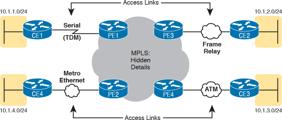
The variety of access links available for MPLS networks makes MPLS a great option for building large enterprise networks. For sites that are near MetroE services, especially for sites that need at least 10 Mbps of bandwidth, using MetroE as an access link makes great sense. Then, for sites that are more remote, the carrier may not offer MetroE services to that area, but many carriers can install a serial link to remote sites. Or, the enterprise may replace an existing Frame Relay or ATM network with MPLS, and in that case, the same physical links can be used, and the carrier can move those over to the MPLS network as MPLS access links.
MPLS and Quality of Service
MPLS was also the first WAN service for which the SP provided effective quality of service (QoS) features. And even though you have not yet gotten to Chapter 18, “Quality of Service (QoS),” you should be able to get a general idea of an MPLS QoS benefit with the following basic example.
IP networks can and often do forward voice traffic in IP packets, called Voice over IP (VoIP). If a WAN service does not provide QoS, that means that the WAN service does not treat one packet any differently than any other packet. With QoS, the SP’s network can treat packets differently, giving some packets (like VoIP) better treatment. For a voice call to sound good, each voice packet must have low loss (that is, few packets are discarded); low one-way delay through the network; and low variation in delay (called jitter). Without QoS, a voice call over an IP network will not sound good.
With a QoS-capable WAN, the customer can mark VoIP packets so that the MPLS network can recognize VoIP packets and treat them better, resulting in better voice call quality. But to make it work correctly, the customer and MPLS provider need to cooperate.
For instance, for VoIP packets travelling left to right in Figure 14-17, Router CE1 could be configured with QoS marking tools. Marking tools could recognize VoIP packets, and place a specific value in the IP header of VoIP packets (a value called DSCP EF, per the figure). The MPLS WAN provider would then configure its QoS tools to react for packets that have that marking, typically sending that packet as soon as possible. The result: low delay, low jitter, low loss, and a better call quality.

Note that Chapter 18 is devoted to these same mechanisms, and others like it.
Summarizing the ideas so far, MPLS supports a variety of access links. An enterprise would select the type and speed of access link for each site based on the capacity (bandwidth) required for each site. Beyond that basic connectivity, the enterprise will want to work with the SP to define other features of the service. The customer and SP will need to work through the details of some Layer 3 design choices (as discussed in more depth in the next section). The customer will also likely want to ask for QoS services from the MPLS provider, and define those details.
Layer 3 with MPLS VPN
Because MetroE provides a Layer 2 service, the SP has no need to understand anything about the customer’s Layer 3 design. The SP knows nothing about the customer’s IP addressing plan, and has no need to participate with routing protocols.
MPLS VPNs take the complete opposite approach. As a Layer 3 service, MPLS must be aware of the customer IP addressing. The SP will even use routing protocols and advertise those customer routes across the WAN. This section takes a closer look at what that means.
First, keep the primary goals in mind. The customer pays good money for a WAN service to deliver data between sites, with certain levels of availability and quality (for instance, low delay, jitter, and loss for VoIP). But to support that base function of allowing packet delivery from each WAN site to the other, the CE routers need to exchange routes with the PE routers in the MPLS network. Additionally, all the CE routers need to learn routes from the other CE routers—a process that relies on the PE routers.
To move into the specifics, first, the CE routers and the PE router on the ends of the same access link need to exchange routes, as shown in Figure 14-18. The figure shows the CE-PE routing protocol neighbor relationships (as lines with circles on the ends). In this case, the customer chose to use EIGRP. However, MPLS allows for many familiar routing protocols on the edge of the MPLS network: RIPv2, EIGRP, OSPF, and even eBGP.
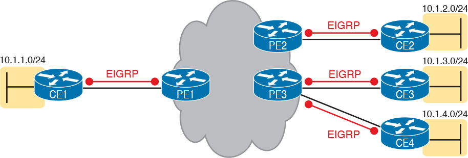
Additionally, all the CE routers need to learn routes from the other CE routers. However, a CE router does not form routing protocol neighbor relationships directly with the other CE routers, as noted in Figure 14-18. Summarizing what does and does not happen:
![]() A CE router does become neighbors with the PE router on the other end of the access link.
A CE router does become neighbors with the PE router on the other end of the access link.
![]() A CE router does not become neighbors with other CE routers.
A CE router does not become neighbors with other CE routers.
![]() The MPLS network will advertise the customer’s routes between the various PE routers, so that the CE routers can learn all customer routes through their PE-CE routing protocol neighbor relationship.
The MPLS network will advertise the customer’s routes between the various PE routers, so that the CE routers can learn all customer routes through their PE-CE routing protocol neighbor relationship.
To advertise the customer routes between the PE routers, the PE routers use another routing protocol along with a process called route redistribution. Route redistribution happens inside one router, taking routes from one routing protocol process and injecting them into another. MPLS does route redistribution in the PE routers between the routing protocol used by the customer and a variation of BGP called Multiprotocol BGP (MPBGP). (Redistribution is needed when the PE-CE routing protocol is not BGP.) Figure 14-19 shows the idea.

Just as a quick aside about MPBGP, MPLS VPNs use MPBGP (as opposed to other routing protocols) because MPBGP can advertise routes from multiple customers while keeping the routes logically separated. For instance, continuing the example in Figure 14-19, Router PE1 might sit in one PoP but connect to dozens of different customers. Likewise, Router PE3 might connect to many of those same customers. MPBGP can advertise routes for all those customers and mark which routes are from which customers, so that only the correct routes are advertised to each CE router for different customers.
OSPF Area Design with MPLS VPN
Now that you know the basics about what happens with routing protocols at the edge of an MPLS network, take a step back and ponder OSPF area design. For all the other WAN services discussed in the book, the WAN service is just one more data link, so the WAN sits inside one area. With MPLS, the MPLS service acts like a bunch of routers. If you use OSPF as the PE-CE routing protocol, some choices must be made about OSPF areas, and about which WAN links are in which area, and where the backbone area can and should be.
MPLS allows for a couple of variations on OSPF area design, but they all use an idea that was added to OSPF for MPLS VPNs, an idea that has come to be known informally as the OSPF super backbone. The idea is an elegant solution that meets OSPF needs and the requirement that the MPLS PEs, when using OSPF, must be in some OSPF area:
![]() The MPLS PEs form a backbone area by the name of a super backbone.
The MPLS PEs form a backbone area by the name of a super backbone.
![]() Each PE-CE link can be any area—a non-backbone area or the backbone area.
Each PE-CE link can be any area—a non-backbone area or the backbone area.
Although the super backbone supports some functions and logic beyond the scope of this book, for the purposes of getting a basic understanding of OSPF’s use with MPLS, you can think of the super backbone as simply the majority of an enterprise’s OSPF backbone area, but with the option to make the backbone area larger. The CE routers at a customer site may not be part of the backbone area, or may be, at the choice of the customer network engineers.
For example, for a nice clean design, each of the four customer sites in Figure 14-20 uses a different area. The PE-CE links are part of those individual areas. The OSPF backbone area still exists, and each area connects to the backbone area, but the backbone exists in the MPLS PE routers only.

The area design in Figure 14-20 provides a clean OSPF area design. However, if migrating from some other type of WAN service, with an existing OSPF design, the network engineers may prefer to keep parts of an existing OSPF design, which means some sites may still need to include the backbone area. In fact, multiple WAN sites can be configured to be in the backbone area, and still function correctly. Figure 14-21 shows one such example.

In effect, the super backbone combines with the two other parts of the network configured as area 0 for one contiguous backbone area. Notice on the left side of Figure 14-21 the two sites with area 0 noted. Normally, if both customer sites implement area 0, but there were links from some other area between them, the design would break OSPF design rules. However, the OSPF backbone (area 0) links on the left, plus the OSPF super backbone area 0 created by MPLS, act together in regard to OSPF design.
Next, focus on the site at the upper left. That site represents what might have existed before migrating to an MPLS design, with Router R1’s links in area 0, and the links connected to Routers R2 and R3 in area 1. The enterprise network engineer may have decided to leave the OSPF area design alone when connecting to the MPLS network. To support those backbone area links off Router R1, the engineer put the CE1-PE1 link into area 0. As a result, the combined customer area 0 instances and the super backbone area 0 creates one contiguous backbone area.
Routing Protocol Challenges with EIGRP
Using EIGRP as the PE-CE routing protocol poses fewer challenges than when using OSPF. However, there is one configuration setting that impacts the routing protocol metrics with EIGRP, so it is worth a brief mention.
With an MPLS service, because of the effects of route redistribution to exchange routes, the PE-CE configuration at each site could use a different EIGRP AS number (ASN) in the configurations. For example, in Figure 14-22, thinking about route exchange from CE1 all the way to CE2, the process uses EIGRP from CE1 to PE1, and from PE2 to CE2. But what happens between PE1 and PE2 is an independent process that does not use EIGRP, but rather MPBGP, so the requirement to use the same ASN on both ends is removed.

Although a customer could use different EIGRP ASNs, EIGRP metrics are more realistic if you use the same EIGRP ASN at all sites. In fact, if the enterprise did use the same EIGRP ASN, the entire MPLS network’s impact on EIGRP metrics would act as if everything between the PEs (in the middle of the MPLS network) did not exist. For instance, with the same ASN used at all sites in Figure 14-22, the EIGRP topology, from a metrics perspective, looks more like the design in Figure 14-23.

Chapter Review
One key to doing well on the exams is to perform repetitive spaced review sessions. Review this chapter’s material using either the tools in the book, DVD, or interactive tools for the same material found on the book’s companion website. Refer to the “Your Study Plan” element for more details. Table 14-4 outlines the key review elements and where you can find them. To better track your study progress, record when you completed these activities in the second column.


Key Terms You Should Know
Multiprotocol Label Switching (MPLS)
Ethernet Virtual Connection (EVC)