
Chapter 15. Private WANs with Internet VPN
This chapter covers the following exam topics:
3.0 WAN Technologies
3.2 Configure, verify and troubleshoot PPPoE client-side interfaces using local authentication
3.3 Configure, verify and troubleshoot GRE tunnel connectivity
3.4 Describe WAN topology options
3.4.a Point-to-point
3.5 Describe WAN access connectivity options
3.5.c Broadband PPPoE
3.5.d Internet VPN (DMVPN, site-to-site VPN, client VPN)
This lengthy chapter covers a wide variety of topics related to how companies can use the Internet as a private wide-area network (WAN) by using virtual private network (VPN) technologies. The stars of this chapter are generic routing encapsulation (GRE) tunnels and PPP over Ethernet (PPPoE). To support those topics, the chapter touches on a variety of related topics, including some Internet access technologies, security basics, and some important VPN protocols such as IP Security (IPsec) and Secure Sockets Layer (SSL).
This chapter breaks the material into three major sections. The first discusses Internet access options and the basics of VPN protocols used over the Internet. The second and third major sections are traditional concept, configure, verify, and troubleshoot sections, with the second section about GRE, and the third about PPPoE.
From a study planning perspective, this chapter is one of the longest chapters in the book. All the topics are related, so I decided to keep them in one larger chapter. However, you can easily treat each major section as a separate chapter from the sense of managing your time.
“Do I Know This Already?” Quiz
Take the quiz (either here, or use the PCPT software) if you want to use the score to help you decide how much time to spend on this chapter. The answers are at the bottom of the page following the quiz, and the explanations are in DVD Appendix C and in the PCPT software.

1. A colleague mentions using a client VPN. Which of the following protocols or technologies would you expect your colleague to have used?
a. SSL
b. IPsec
c. GRE
d. DMVPN
2. An engineer configures a point-to-point GRE tunnel between two Cisco routers, called A and B. The routers use public IP addresses assigned by ISPs, and private addresses from network 10.0.0.0. Which of the following answers accurately describes where the addresses could be referenced in the GRE configuration?
a. Router A’s private address on an ip address command on Router A’s tunnel interface
b. Router A’s private address on a tunnel destination command on Router B
c. Router B’s public address on a tunnel source command on Router A
d. Router B’s public address on an ip address command on Router B’s tunnel interface
3. An enterprise uses a site-to-site GRE tunnel that runs over the Internet between two routers (R1 and R2). R1 uses tunnel interface 22. The tunnel has a source of 1.1.1.1 and a destination of 2.2.2.2. All the answers list facts that could be true, but which of the following must be true when Router R1’s tunnel 22 is in an up/up state?
a. 2.2.2.2 is pingable from Router R1.
b. 1.1.1.1 is pingable from Router R2.
c. R1 has a working (up/up) interface with address 1.1.1.1.
d. R2 has a working (up/up) interface with address 2.2.2.2.
4. An enterprise has 1000 small retail locations and a central site. The enterprise uses Internet access links to each retail store and DMVPN to securely create a VPN back to the central site. Which of the following answers is true about the operation and configuration of DMVPN?
a. The hub router needs at least 1000 tunnel interfaces.
b. The hub router needs less than 10 tunnel interfaces.
c. All packets between retail stores must route through the central hub site.
d. Packets cannot be forwarded from one retail store to another.
5. An enterprise uses Cisco IOS routers and DSL connections to local ISPs for their retail locations. The ISPs require the use of PPPoE. The routers at each retail site use dynamically learned public IP addresses as learned from the ISPs. Each router uses its F0/0 interface to connect to an external DSL modem, which then connects to a phone line. Which of the following is the most likely choice for configuring the router to use the IP address as assigned by the ISP?
a. Interface F0/0 has an ip address dhcp interface subcommand.
b. Some dialer interface has an ip address dhcp interface subcommand.
c. Some dialer interface has an ip address negotiated interface subcommand.
d. Interface F0/0 has an ip address negotiated interface subcommand.
6. An enterprise uses Cisco IOS routers and DSL connections to local ISPs for their retail locations. The ISPs require the use of PPPoE. The following output listed comes from one such router (R1). Which of the following answers are true about the configuration on Router R1 and its current PPPoE state? (Choose two answers.)
R1# show pppoe session
1 client session
Uniq ID PPPoE RemMAC Port VT VA State
SID LocMAC VA-st Type
N/A 1 0200.0000.3333 Gi0/0 Di1 Vi1 UP
0200.0000.3003 UP
a. The configuration includes PPPoE commands under interface virtual-access 1.
b. Dialer interface 1 and virtual-access 1 are bound together.
c. Interface G0/0 is using MAC address 0200.0000.3333.
d. The PPPoE session is currently working.
7. An enterprise uses Cisco IOS routers and DSL connections to local ISPs for their retail locations. The ISPs require the use of PPPoE. A network engineer connects to the console of one router at a retail office, issues the show pppoe session command, and the router just returns a command prompt, with no lines of output. If you knew the problem was related to the configuration on the local router, which one of the four following areas would be the best area to recommend for your colleagues to investigate in their next troubleshooting step?
a. Look at the commands on the physical Ethernet interface
b. Look at the dialer interface commands specific to PPP
c. Look at the commands specific to IPv4 address learning
d. Look at the commands in the running-config file for the virtual-access interface
Answers to the “Do I Know This Already?” quiz:
1 A 2 A 3 C 4 B 5 C 6 B, D 7 A
Foundation Topics
Internet Access and Internet VPN Fundamentals
To build the Internet, Internet service providers (ISP) need links to other ISPs as well as links to the ISPs’ customers. The Internet core connects ISPs to each other using a variety of high-speed technologies. Additionally, Internet access links connect an ISP to each customer, again with a wide variety of technologies. The combination on ISP networks and customer networks that connect to the ISPs together create the worldwide Internet.
For these customer access links, the technologies need to be inexpensive so that a typical consumer can afford to pay for the service. But businesses can use many of these same technologies to connect to the Internet. Some WAN technologies happen to work particularly well as Internet access technologies. For example, several use the same telephone line installed into most homes by the phone company so that the ISPs do not have to install additional cabling. Others use the cable TV cabling, whereas others use wireless.
While consumers connect to the Internet to reach destinations on the Internet, businesses can also use the Internet as a WAN service. An enterprise can connect each business site to the Internet. Then, using virtual private network (VPN) technology, the enterprise can create an Internet VPN. An Internet VPN can keep the enterprise’s packet private through encryption and other means, even while sending the data over the Internet.
This first of three major sections of the chapter reviews some of the basics of Internet access links. These details are needed as background for some of the exam topics discussed later in the chapter. This section then introduces the basics of how an enterprise can communicate securely over the internet, making the public Internet act like a private network, by creating an Internet VPN.
Internet Access
Private WAN technology may be used to access an ISP’s network, including all the private WAN technologies discussed in Chapter 14, “Private WANs with Ethernet and MPLS.” Businesses often use time-division multiplexing (TDM) serial links, Multiprotocol Label Switching (MPLS), or Metro Ethernet to access the Internet. Figure 15-1 shows a few of these, just as a visual reminder of these options.

The next few pages review some of the Internet access technologies not yet discussed elsewhere in the book. These topics exist to give you a little more context about the more detailed topics of building Internet VPNs.
Digital Subscriber Line
In the consumer Internet access space, one big speed breakthrough happened with the introduction of the digital subscriber line (DSL). It represented a big technological breakthrough in terms of raw speed in comparison to some older technologies, such as analog modems. These faster speeds available through DSL also changed how people could use the Internet, because many of today’s common applications would be unusable with the earlier Internet access technologies (analog modems and Integrated Services Digital Network, or ISDN).
Note
If you are interested in a few pages of information about the older Internet access technologies of analog modems and ISDN, look to this book’s DVD Appendix K, “Topics from Previous Editions,” for a section titled “Dial Access with Modems and ISDN.”
Telephone companies (telcos) greatly influenced the creation of DSL. As a technology, DSL gave telcos a way to offer much faster Internet access speeds. As a business opportunity, DSL gave telcos a way to offer a valuable high-speed Internet service to many of their existing telephone customers, over the same physical phone line already installed, which created a great way for telcos to make money.
Figure 15-2 shows some of the details of how DSL works on a home phone line. The phone can do what it has always done: plug into a phone jack and send analog signals. For the data, a DSL modem connects to a spare phone outlet. The DSL modem sends and receives the data, as digital signals, at higher frequencies, over the same local loop, even at the same time as a telephone call. (Note that the physical installation often uses frequency filters that are not shown in the figure or discussed here.)

Because DSL sends analog (voice) and digital (data) signals on the same line, the telco has to somehow split those signals on the telco side of the connection. To do so, the local loop must be connected to a DSL access multiplexer (DSLAM) located in the nearby telco central office (CO). The DSLAM splits out the digital data over to the router on the lower right in Figure 15-2, which completes the connection to the Internet. The DSLAM also splits out the analog voice signals over to the voice switch on the upper right.
DSL has some advantages and disadvantages, of course. For instance, one variation of DSL, called asymmetric DSL (ADSL), offers a faster speed toward the customer (download speed), which better matches the traffic patterns of most consumer traffic. Many consumer ADSL offerings routinely support speeds in the 5-Mbps range, and up to 24 Mbps in ideal conditions. (DSL includes other options that have symmetric speeds as well.) However, DSL works only at certain distances from the CO to the customer site, and the speeds degrade at those longer cabling distances. So, the quality of the DSL service, or availability of the service at all, may be impacted simply by the distance between the home/business site and the CO.
Cable Internet
DSL uses the local link (telephone line) from the local telco. Cable Internet instead uses the cabling from what has become the primary competitor to the telco in most markets: the cable company.
Cable Internet creates an Internet access service which, when viewed generally rather than specifically, has many similarities to DSL. Like DSL, cable Internet takes full advantage of existing cabling, using the existing cable TV (CATV) cable to send data. Like DSL, cable Internet uses asymmetric speeds, sending data faster downstream than upstream, which works well for most consumer locations. And cable Internet still allows the normal service on the cable (cable TV), at the same time as the Internet access service is working.
Cable Internet also uses the same general idea for in-home cabling as DSL, just using CATV cabling instead of telephone cabling. The left side of Figure 15-3 shows a TV connected to the CATV cabling, just as it would normally connect. At another cable outlet, a cable modem connects to the same cable. The Internet service flows over one frequency, like yet another TV channel, just reserved for Internet service.

Similar to DSL, on the CATV company side of the connection (on the right side of the figure), the CATV company must split out the data and video traffic. Data flows to the lower right, through a router, to the Internet. The video comes in from video dishes for distribution out to the TVs in people’s homes.
Wireless WAN (3G, 4G, LTE)
Many of you reading this book have a mobile phone that has Internet access. That is, you can check your email, surf the Web, download apps, and watch videos. Many of us today rely on our mobile phones, and the Internet access built in to those phones, for most of our tweets and the like. This section touches on the big concepts behind the Internet access technology connecting those mobile phones.
Mobile phones use radio waves to communicate through a nearby mobile phone tower. The phone has a small radio antenna, and the provider has a much larger antenna sitting at the top of a tower somewhere within miles of you and your phone. Phones, tablet computers, laptops, and even routers (with the correct interface cards) can communicate through to the Internet using this technology, as represented in Figure 15-4.

The mobile phone radio towers also have cabling and equipment, including routers. The mobile provider builds its own IP network, much like an ISP builds out an IP network. The customer IP packets pass through the IP router at the tower into the mobile provider’s IP network and then out to the Internet.
The market for mobile phones and wireless Internet access for other devices is both large and competitive. As a result, the mobile providers spend a lot of money advertising their services, with lots of names for one service or the other. Frankly, it can be difficult to tell what all the marketing jargon means, but a few terms tend to be used throughout the industry:
Wireless Internet: A general term for Internet services from a mobile phone or from any device that uses the same technology.
3G/4G Wireless: Short for third generation and fourth generation, these terms refer to the major changes over time to the mobile phone companies’ wireless networks.
LTE: Long-Term Evolution, which is a newer and faster technology considered to be part of fourth generation (4G) technology.
The takeaway from all this jargon is this: When you hear about wireless Internet services with a mobile phone tower in the picture—whether the device is a phone, tablet, or PC—it is probably a 3G, 4G, or LTE wireless Internet connection.
Fiber Internet Access
The consumer-focused Internet access technologies discussed in this section use a couple of different physical media. DSL uses the copper wiring installed between the telco CO and the home. Cable uses the copper CATV cabling installed from the cable company to the home. And of course wireless WAN technologies do not use cables.
The cabling used by DSL and cable Internet uses copper wires, but, comparing different types of physical media, fiber-optic cabling generally supports faster speeds for longer distances. That is, just comparing physical layer technologies across the breadth of networking, fiber-optic cabling supports longer links, and those links often run at equivalent or faster speeds.
Some ISPs now offer Internet access that goes by the name of fiber Internet, or simply fiber. To make that work, some local company that owns the rights to install cabling underground in a local area (often a telephone company) installs new fiber-optic cabling. Once the cable plant is in place (a process that often takes years as well as a large budget), the fiber ISP then connects customers to the Internet using the fiber-optic cabling. Often, the fiber uses Ethernet protocols over the fiber. The end result: high-speed Internet to the home, often using Ethernet technology.
Internet VPN Fundamentals
Private WANs have some wonderful security features. In particular, the customers who send data through the WAN have good reason to believe that no attackers saw the data in transit, or even changed the data to cause some harm. The private WAN service provider promises to send one customer’s data to other sites owned by that customer, but not to sites owned by other customers, and vice versa.
VPNs try to provide the same secure features as a private WAN while sending data over a network that is open to other parties (such as the Internet). Compared to a private WAN, the Internet does not provide for a secure environment that protects the privacy of an enterprise’s data. Internet VPNs can provide important security features, like:
![]() Confidentiality (privacy): Preventing anyone in the middle of the Internet (man in the middle) from being able to read the data
Confidentiality (privacy): Preventing anyone in the middle of the Internet (man in the middle) from being able to read the data
![]() Authentication: Verifying that the sender of the VPN packet is a legitimate device and not a device used by an attacker
Authentication: Verifying that the sender of the VPN packet is a legitimate device and not a device used by an attacker
![]() Data integrity: Verifying that the packet was not changed as the packet transited the Internet
Data integrity: Verifying that the packet was not changed as the packet transited the Internet
![]() Anti-replay: Preventing a man in the middle from copying and later replaying the packets sent by a legitimate user, for the purpose of appearing to be a legitimate user
Anti-replay: Preventing a man in the middle from copying and later replaying the packets sent by a legitimate user, for the purpose of appearing to be a legitimate user
To accomplish these goals, two devices near the edge of the Internet create a VPN, sometimes called a VPN tunnel. These devices add headers to the original packet, with these headers including fields that allow the VPN devices to make the traffic secure. The VPN devices also encrypt the original IP packet, meaning that the original packet’s contents are undecipherable to anyone who happens to see a copy of the packet as it traverses the Internet.
Figure 15-5 shows the general idea of what typically occurs with a VPN tunnel. The figure shows a VPN created between a branch office router and a Cisco Adaptive Security Appliance (ASA), which is one of Cisco’s product names for a firewall. In this case, the VPN is called a site-to-site VPN because it connects two sites of a company.

The figure shows the following steps, which explain the overall flow:
1. Host PC1 (10.2.2.2) on the right sends a packet to the web server (10.1.1.1), just as it would without a VPN.
2. The router encrypts the packet, adds some VPN headers, adds another IP header (with public IP addresses), and forwards the packet.
3. An attacker in the Internet copies the packet (called a man-in-the-middle attack). However, the attacker cannot change the packet without being noticed and cannot read the contents of the original packet.
4. Device ASA-1 receives the packet, confirms the authenticity of the sender, confirms that the packet has not been changed, and then decrypts the original packet.
5. Server S1 receives the unencrypted packet.
The benefits of using an Internet-based VPN as shown in Figure 15-5 are many. The cost of a high-speed Internet connection as discussed in the early pages of this chapter is usually much less than that of many private WAN options. The Internet is seemingly everywhere, making this kind of solution available worldwide. And by using VPN technology and protocols, the communications are secure.
The term tunnel refers to any protocol’s packet that is sent by encapsulating the packet inside another packet. The term VPN tunnel may or may not imply that the tunnel also uses encryption. Many of the VPN tunnels discussed in this chapter would normally include encryption when used in production.
Site-to-Site VPNs with IPsec
As just discussed regarding the example shown in Figure 15-5, a site-to-site VPN means that two enterprise sites create a VPN tunnel by encrypting and sending data between two devices. One set of rules for creating a site-to-site VPN is defined by IPsec.
IPsec is an architecture or framework for security services for IP networks. The name itself is not an acronym, but rather a name derived from the title of the RFC that defines it (RFC 4301, Security Architecture for the Internet Protocol), more generally called IP Security, or IPsec.
IPsec defines how two devices, both of which connect to the Internet, can achieve the main goals of a VPN as listed at the beginning of this chapter: confidentiality, authentication, data integrity, and anti-replay. IPsec does not define just one way to implement a VPN, instead allowing several different protocol options for each VPN feature. One of IPsec’s strengths is that its role as an architecture allows it to be added to and changed over time as improvements to individual security functions are made.
This chapter does not go through the details of each part of IPsec, but to give you some general idea of some of IPsec’s work, this section shows how two IPsec endpoints encrypt data and add IPsec VPN headers to the encrypted data.
The idea of IPsec encryption might sound intimidating, but if you ignore the math—and thankfully, you can—IPsec encryption is not too difficult to understand. IPsec encryption uses a pair of encryption algorithms, which are essentially math formulas, to meet a couple of requirements. First, the two math formulas are a matched set:
![]() One to hide (encrypt) the data
One to hide (encrypt) the data
![]() Another to re-create (decrypt) the original data based on the encrypted data
Another to re-create (decrypt) the original data based on the encrypted data
Besides those somewhat obvious functions, the two math formulas were chosen so that if an attacker intercepted the encrypted text but did not have the secret password (called an encryption key), decrypting that one packet would be difficult. In addition, the formulas are also chosen so that if an attacker did happen to decrypt one packet, that information would not give the attacker any advantages in decrypting the other packets.
The process for encrypting data for an IPsec VPN works generally as shown in Figure 15-6. Note that the encryption key is also known as the session key, shared key, or shared session key.

The four steps highlighted in the figure are as follows:
1. The sending VPN device (like the remote office router in Figure 15-5) feeds the original packet and the session key into the encryption formula, calculating the encrypted data.
2. The sending device encapsulates the encrypted data into a packet, which includes the new IP header and VPN header.
3. The sending device sends this new packet to the destination VPN device (ASA-1 back in Figure 15-5).
4. The receiving VPN device runs the corresponding decryption formula, using the encrypted data and session key—the same key value as was used on the sending VPN device—to decrypt the data.
Client VPNs with SSL
The Secure Sockets Layer (SSL) protocol serves as an alternative VPN technology to IPsec. In particular, today’s web browsers support SSL as a way to dynamically create a secure connection from the web browser to a web server, supporting safe online access to financial transactions. This brief topic explains a few details about how you can use SSL to create client VPNs.
Web browsers use HTTP as the protocol with which to connect to web servers. However, when the communications with the web server need to be secure, the browser switches to use SSL. SSL uses well-known port 443, encrypting data sent between the browser and the server and authenticating the user. Then, the HTTP messages flow over the SSL VPN connection.
The built-in SSL functions of a web browser create one secure web browsing session, but this same SSL technology can be used to create a client VPN using a Cisco VPN client. The Cisco AnyConnect Secure Mobility Client (or AnyConnect Client for short) is software that sits on a user’s PC and uses SSL to create one end of a VPN remote-access tunnel. As a result, all the packets sent to the other end of the tunnel are encrypted, not just those sent over a single HTTP connection in a web browser.
For example, the VPN tunnel shown for PC A in Figure 15-7 uses the AnyConnect Client to create a client VPN. The AnyConnect Client creates an SSL tunnel to the ASA firewall that has been installed to expect VPN clients to connect to it. The tunnel encrypts all traffic, so that PC A can use any application available at the enterprise network on the right.

Note that while the figure shows an ASA firewall used at the main enterprise site, many types of devices can be used on the server side of an SSL connection as well. The web server itself can be the endpoint of an SSL connection from a web browser, but often, to improve server performance, the SSL tunnel on the server side terminates on specialized devices like the Cisco ASA or a router.
The bottom of Figure 15-7 shows a client VPN that supports a web application for a single web browser tab. The experience is much like when you connect to any other secure website today: the session uses SSL, so all traffic sent to and from that web browser tab is encrypted with SSL. Note that PC B does not use the AnyConnect Client; the user simply opens a web browser to browse to server S2. However, by using SSL, that one session is encrypted with SSL, providing better security.
GRE Tunnels and DMVPN
The device on the endpoint of an Internet VPN takes a normal unencrypted packet and performs several functions before forwarding that packet. One of those functions is to encrypt the packet, and another is to encapsulate the packet in a new IP header. The new IP header uses addresses in the unsecured network (usually the Internet), allowing the routers between the two VPN tunnel endpoints to forward the VPN IP packet. The original IP packet, including the original IP header, is encrypted and unreadable.
This second major section of this chapter examines a subset of the work to create that kind of site-to-site VPN tunnel. In particular, this section looks at how to set up the tunnel, while ignoring the encryption function. Specifically, this section looks at the concepts and configuration of how routers create a tunnel, encapsulating the original IP packet inside another IP packet. The goal is to give you some general ideas about how tunneling works, while leaving the detailed security configuration to other certifications like CCNA Security.
This section concludes with a short discussion of Dynamic Multipoint VPN (DMVPN). DMVPN helps solve some shortcomings with deploying point-to-point GRE tunnels on a larger scale.
GRE Tunnel Concepts
This chapter looks at one type of IP tunnel: generic routing encapsulation (GRE). GRE, defined in RFC 2784, defines an additional header used by GRE to perform tunneling, along with the new IP header, that encapsulates the original packet. Two routers work together, with matching configuration settings, to create a GRE IP tunnel. Then, IPsec configuration can be added to encrypt the traffic.
The discussion of GRE tunnels looks at the concepts from several perspectives. The first section shows how packets can be routed over a GRE tunnel, much like using a serial link inside a secured enterprise network. The rest of this topic then explains how GRE does its work.
Routing over GRE Tunnels
A GRE tunnel exists between two routers, with the tunnel working very much like a serial link with regard to packet forwarding. So, before discussing GRE tunnels, this section first reviews some familiar facts about routers and serial links, using Figure 15-8 as an example.

The small network in Figure 15-8 looks like a part of many enterprise networks. It uses private IP addresses (network 10.0.0.0). It has an IP address on each router interface, including on each serial interface. The IP addresses on the serial interfaces (10.1.3.1 and 10.1.3.2, respectively) are in the same subnet. And when PC1 sends a packet to destination IP address 10.1.2.2, R1 will encapsulate the packet in the data link protocol used on the link, like the default High-level Data Link Control (HDLC) encapsulation shown in the figure.
Also, note that all the parts of this small enterprise network exist in secure spaces. This network has no need to encrypt data using a VPN.
GRE creates a concept that works just like the serial link in Figure 15-8, at least with regard to IP routing. Instead of a serial link with serial interfaces, the routers use virtual interfaces called tunnel interfaces. The two routers have IP addresses on their tunnel interfaces in the same subnet. Figure 15-9 shows an example where the serial link has been replaced with these virtual tunnel interfaces.

Sticking with the big ideas about IP routing for now, the tunnel looks like just another link in the secure part of the network. The tunnel IP addresses are from the secure enterprise network. The routers encapsulate the original packet inside a tunnel header, which takes the place of the serial link’s HDLC header. And the routers will even have routes that list the tunnel interfaces (Tunnel0 and Tunnel1 in this case) as the outgoing interfaces.
To make use of the GRE tunnel, the routers treat it like any other link with a point-to-point topology. The routers have IPv4 addresses in the same subnet. The routers use a routing protocol to become neighbors and exchange routes over the tunnel. And the routes learned over the tunnel list the tunnel interface as the outgoing interface, with the neighboring router’s tunnel interface IP address as the next-hop router. Figure 15-10 shows an example, with the routes learned by each router listed at the bottom.

Look closely at the route for subnet 10.1.2.0/24. The subnet exists on the right side of the figure, connected to R2. R1 has learned a route for the 10.1.2.0/24 subnet, as learned from R2. (R1’s routing table is on the left side of the figure.) To create that route, first R2 will have a connected route to subnet 10.1.2.0/24. R1 and R2 will use some routing protocol (for instance, OSPF) to exchange routing information. R1 will add a new route for subnet 10.1.2.0/24.
Most importantly, note the use of the tunnel interface in the route as shown beneath Router R1 in the figure. That route will list R1’s own tunnel interface, Tunnel0, as the outgoing interface. That route lists R2’s tunnel interface IP address, 10.1.3.2, as the next-hop router, as shown in R1’s IP routing table in the bottom-left part of the figure.
Note
From a Layer 3 perspective, the tunnel interface shown in this example works like a point-to-point link. In fact, the tunnel shown in the examples so far is called a point-to-point GRE tunnel. DMVPN also uses GRE, but it uses multipoint GRE tunnels, which have more than two endpoints in the same tunnel.
All these concepts show how the GRE tunnel acts like just one more link in the secure part of an internetwork. The next few pages look at how GRE tunnels forward these packets over an unsecure network between the two routers.
GRE Tunnels over the Unsecured Network
The previous few figures have a tunnel between two routers, one that looks like a pipe, but those diagrams do not tell us much about the physical network behind the tunnel. The tunnel can exist over any IP network. The tunnel is created using an IP network to forward the original packets, so any IP network between Routers R1 and R2 would allow the tunnel to exist.
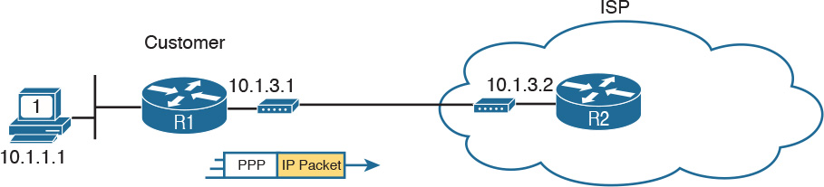
Often, site-to-site VPNs, like the one shown in Figure 15-10, use an unsecured network like the Internet as the IP network. The whole idea ties back to economics. The monthly cost of high-speed Internet access at each site is often less than paying for other private WAN services. But no matter what type of Internet connection exists, the routers on the tunnel can use the Internet as a way to forward the packets between the two tunnel routers, as shown in Figure 15-11.

The routers on the ends of the GRE tunnel create the tunnel by agreeing to send each other packets over the unsecure network between the two. Figure 15-11 shows many of the details that the engineer needs to know about the two routers before configuring the GRE tunnel on both ends. The figure shows the interfaces R1 and R2 each use to connect to the Internet. And it shows the IP addresses each router uses on its Internet connections, in this case 1.1.1.1 and 2.2.2.2 just to use more memorable numbers.
The router configuration uses virtual interfaces called tunnel interfaces. These interfaces do not exist until the engineer creates the tunnel with the interface tunnel command. For instance, the command interface tunnel 0 creates a tunnel interface numbered as 0. To create a tunnel, both routers create a tunnel interface and use IP addresses as if the tunnel were a point-to-point link.
Figure 15-12 shows a conceptual diagram of a packet coming into Router R1 from PC1, one that needs to be forwarded over the GRE tunnel to Server S1 (10.1.2.2). When the router uses its IP routing logic from the secured part of the network, as shown in Figure 15-9, R1 wants to send the packet over the tunnel. Figure 15-12 shows the encapsulation done by R1.

Note
If the two routers creating this tunnel also configured the IPsec encryption part of the tunnel, before encapsulating the original packet as shown in Figure 15-11, the sending router would first encrypt the original packet.
GRE specifies the use of two headers to create the tunnel. GRE defines its own header, used to manage the tunnel itself. GRE also defines the use of a complete 20-byte IP header, called the delivery header. This header will use IP addresses from the unsecure network. In this case, the delivery IP header will list R1’s 1.1.1.1 Internet IP address as the source and R2’s 2.2.2.2 Internet IP address as the destination.
While this packet passes through the Internet, the routers in the Internet use this outer GRE delivery IP header to route the packet. The fact that this packet happens to hold another entire IP packet inside does not matter to the IP forwarding process in those routers; they just forward the IP packet based on the 2.2.2.2 destination IP address. Figure 15-13 shows the concept; note that this packet may be routed by many routers in the Internet before arriving at R2.

When the GRE packet in Figure 15-13 finally arrives on the right side of the Internet, at R2, R2 needs to extract the original IP packet. With physical links, R2 would normally simply remove the old incoming data link header. With a GRE-encapsulated packet, the receiving router (R2) also needs to remove the delivery header and the GRE header, leaving the original packet, as shown in Figure 15-14.

If the routers also configured the IPsec encryption part of the tunnel, just after the steps shown in Figure 15-14, the receiving router would then decrypt the original packet.
Configuring GRE Tunnels
Configuring GRE tunnels requires only a few commands. The challenge with GRE configuration comes in organizing the configuration parameters. The configuration requires a tunnel interface, with IP addresses from the secured part of the network configured with the ip address interface command. It also requires that the two routers declare both their own IP address (source) and the other router’s IP address (destination), used in the unsecure part of the network. Figure 15-15 shows the organization of the various configuration parameters.

The following list details the configuration steps on each router:
Step 1. Use the interface tunnel number global command to create a tunnel interface. The interface numbers have local meaning only and do not have to match between the two routers.
Step 2. (Optional) Use the tunnel mode gre ip interface subcommand in tunnel interface mode to tell IOS to use GRE encapsulation on the tunnel. (This is the default setting for a tunnel interface.)
Step 3. Use the ip address address mask interface subcommand to assign an IP address to the tunnel interface, using a subnet from the secure network’s address range. The two routers on the tunnel should use addresses from the same subnet.
Step 4. Configure the tunnel’s source IP address in the unsecured part of the network in one of two ways. Regardless of the method, the local router’s source IP address must match the other router’s tunnel destination.
Step 4A. Use the tunnel source ip-address tunnel interface subcommand to directly set the tunnel’s source IP address.
Step 4B. Use the tunnel source interface-id tunnel interface subcommand to indirectly set the tunnel’s source IP address by referencing an interface on the local router.
Step 5. Use the tunnel destination {ip-address | hostname} command to configure the tunnel’s destination IP address in the unsecured part of the network. (This value must match the IP address used by the other router as its tunnel source IP address.)
Step 6. Add routes that use the tunnel by enabling a dynamic routing protocol on the tunnel or by configuring static IP routes.
As usual, an example can help quite a bit. The example, as you probably guessed, matches the example used throughout the last several pages, as shown in Figures 15-9 through 15-14. Figure 15-16 repeats all the interface numbers and IP addresses for reference. R1 and R2 form a tunnel using public addresses 1.1.1.1 and 2.2.2.2, respectively, in the unsecured network (the Internet). The tunnel uses private subnet 10.1.3.0/24, with R1 and R2 using IP addresses 10.1.3.1 and 10.1.3.2, respectively. Example 15-1 shows the configuration on R1, and Example 15-2 shows the configuration on R2.

Example 15-1 Tunnel Configuration on R1
R1# show running-config
! Only the related configuration is listed
interface serial 0/0/0
ip address 1.1.1.1 255.255.255.0
!
interface tunnel0
ip address 10.1.3.1 255.255.255.0
tunnel mode gre ip
tunnel source serial0/0/0
tunnel destination 2.2.2.2
! The OSPF configuration enables OSPF on the tunnel interface as well.
router ospf 1
network 10.0.0.0 0.255.255.255 area 0
Example 15-2 Tunnel Configuration on R2
R2# show running-config
! Only the related configuration is listed
interface serial 0/0/1
ip address 2.2.2.2 255.255.255.0
!
interface tunnel1
ip address 10.1.3.2 255.255.255.0
tunnel mode gre ip
tunnel source serial0/0/1
tunnel destination 1.1.1.1
! The OSPF configuration enables OSPF on the tunnel interface as well.
router ospf 1
network 10.0.0.0 0.255.255.255 area 0
Just to make sure the matching logic is clear, take a look at R2’s configuration. R2’s S0/0/1 interface has been configured with IP address 2.2.2.2. Then, under interface tunnel 1, the tunnel source Serial0/0/1 command refers to that same interface, making R2’s source IP address for the tunnel 2.2.2.2. Finally, referring back up to R1’s configuration, its tunnel destination 2.2.2.2 command clearly refers to the same IP address used by R2 as its source address. The same trail can be checked for R1’s source address of 1.1.1.1 and R2’s destination address 1.1.1.1.
Note also that IOS supports a variety of tunnel modes, each of which can change the encapsulation used on the tunnel as well as changing some other behaviors. The example shows the tunnel mode gre ip command just to let you see the command, although this command configures the default setting. That default setting tells IOS to use the encapsulation as shown in Figure 15-12: a delivery header that uses IP (that is, IPv4), with a GRE header to follow.
Although this chapter does not happen to include configurations that use other tunnel mode command options, it is easy to understand a few other options. For instance, a tunnel mode gre ipv6 command would be used to create a point-to-point GRE tunnel that uses IPv6 to encapsulate the packets instead of IPv4. As another example, the command tunnel mode gre multipoint is used when configuring Dynamic Multipoint VPN (DMVPN), a topic discussed to a conceptual level later in this chapter.
Verifying a GRE Tunnel
The ultimate test of the tunnel is whether it can pass end-user traffic. However, some other show commands from the router tell us a lot about the status before trying a ping or traceroute from the user’s device.
First, because the tunnel acts very much like a serial link, with interfaces on both routers, the usual commands that list interface status, IP addresses, and IP routes all show information about the GRE tunnel. For instance, Example 15-3 shows the familiar show ip interface brief command on R1, with R1’s Tunnel0 interface highlighted.
Example 15-3 Displaying the Interface State and IP Addresses, Including the Tunnel Interface
R1# show ip interface brief
Interface IP-Address OK? Method Status Protocol
GigabitEthernet0/0 10.1.1.9 YES manual up up
GigabitEthernet0/1 unassigned YES manual administratively down down
Serial0/0/0 1.1.1.1 YES manual up up
Serial0/0/1 unassigned YES manual administratively down down
Tunnel0 10.1.3.1 YES manual up up
The show interfaces tunnel interface-number command lists many counters plus the configuration settings, in addition to the interface status. Example 15-4 lists a sample, again for R1’s Tunnel0 interface. Note that it lists the local router (R1) configuration of the source (1.1.1.1) and destination (2.2.2.2) IP addresses, and it confirms the use of GRE encapsulation over IP (IPv4), as highlighted in the example.
Example 15-4 Tunnel Interface Details
R1# show interfaces tunnel0
Tunnel0 is up, line protocol is up
Hardware is Tunnel
Internet address is 10.1.3.1/24
MTU 17916 bytes, BW 100 Kbit/sec, DLY 50000 usec,
reliability 255/255, txload 1/255, rxload 1/255
Encapsulation TUNNEL, loopback not set
Keepalive not set
Tunnel source 1.1.1.1 (Serial0/0/0), destination 2.2.2.2
Tunnel Subblocks:
src-track:
Tunnel0 source tracking subblock associated with Serial0/0/0
Set of tunnels with source Serial0/0/0, 1 member (includes iterators), on
interface <OK>
Tunnel protocol/transport GRE/IP
! Lines omitted for brevity
Although a working tunnel interface is important, the routers will not use the tunnel interface unless routes try to forward packets over the tunnel interface. The configuration in this example shows that OSPF has been enabled on all interfaces in Class A network 10.0.0.0, the secure part of the internetwork. As a result, the routers should exchange OSPF routes and learn the same routes shown earlier in Figure 15-10. Example 15-5 shows proof, with R1 listing an OSPF-learned route to R2’s LAN subnet of 10.1.2.0/24.
Example 15-5 R1 Routes in Network 10.0.0.0
R1# show ip route 10.0.0.0
Routing entry for 10.0.0.0/8, 5 known subnets
Attached (4 connections)
Variably subnetted with 2 masks
C 10.1.1.0/24 is directly connected, GigabitEthernet0/0
L 10.1.1.9/32 is directly connected, GigabitEthernet0/0
O 10.1.2.0/24 [110/1001] via 10.1.3.2, 00:07:55, Tunnel0
C 10.1.3.0/24 is directly connected, Tunnel0
L 10.1.3.1/32 is directly connected, Tunnel0
! Lines omitted for brevity
Note
The show ip route 10.0.0.0 command lists the known routes inside network 10.0.0.0.
Finally, to prove the tunnel can forward traffic, the user can generate some traffic, or a handy extended ping or traceroute can serve as well. Example 15-6 shows an extended traceroute, sourced from R1’s LAN IP address of 10.1.1.9, and sent to server 1’s 10.1.2.2 IP address.
Example 15-6 Extended Traceroute Shows the Tunnel Is Working
R1# traceroute
Protocol [ip]:
Target IP address: 10.1.2.2
Source address: 10.1.1.9
Numeric display [n]:
Timeout in seconds [3]:
Probe count [3]:
Minimum Time to Live [1]:
Maximum Time to Live [30]:
Port Number [33434]:
Loose, Strict, Record, Timestamp, Verbose[none]:
Type escape sequence to abort.
Tracing the route to 10.1.2.2
VRF info: (vrf in name/id, vrf out name/id)
1 10.1.3.2 0 msec 4 msec 0 msec
2 10.1.2.2 4 msec 4 msec 0 msec
R1#
Example 15-6 shows that the traceroute completes, and it also lists R2’s tunnel IP address (10.1.3.2) as the first router in the route. Note that the traceroute command does not list any routers in the unsecure part of the network, because the packets created by the traceroute command get encapsulated and sent from R1 to R2, just like any other packet.
Troubleshooting GRE Tunnels
In its most basic form, the configuration for a point-to-point GRE tunnel between two Cisco routers is simple. You refer to your own public IP address, either directly or by referencing an interface. You refer to the destination router, either by IP address or hostname. And you probably will configure some private IP addresses to make use of the tunnel. That is all you need to do to make a GRE tunnel work, assuming everything else works, such as the Internet connections on both ends.
From that summary, it may seem like there is little to discuss for troubleshooting GRE. This section takes a few pages to work through a couple of items that could prevent a GRE tunnel from working, going a bit beyond a configuration mistake in the relatively sparse GRE configuration.
Tunnel Interfaces and Interface State
The first and easiest configuration item to check is to make sure that the two routers refer to the correct IP addresses in the unsecure part of the network (typically the Internet). These are the addresses referenced by the tunnel source and tunnel destination commands. Earlier, Figure 15-15 showed the idea: The source address on one router should be the destination address on the other, and vice versa.
Of all the items that must be true before a point-to-point GRE tunnel works correctly, most, but not all, are tied to the tunnel interface state. For the tunnel to work, the tunnel interfaces on the endpoint routers must both reach an up/up state. To reach an up/up state, a tunnel interface must be configured with a tunnel source command and a tunnel destination command. Additionally, the following must be true of the tunnel source:

1. If configuring the tunnel source command by referencing a source interface, the interface must
![]() Have an IP address assigned to it
Have an IP address assigned to it
![]() Be in an up/up state
Be in an up/up state
2. If configuring the tunnel source command by referencing a source IP address, the address must
![]() Be an address assigned to an interface on the local router
Be an address assigned to an interface on the local router
![]() Be in an up/up state for that interface on which the address is configured
Be in an up/up state for that interface on which the address is configured
In short, however it is referenced, the tunnel source must be an IP address on the local router on a currently working interface. If that is not true, the tunnel interface will remain in an up/down state. (Note that when a tunnel interface is created, it begins with an up/down state, because it has neither a tunnel source nor tunnel destination configured by default.)
A router’s tunnel interface state is also impacted by the tunnel destination configuration, but those details can be a little trickier. Some settings cause IOS to accept the configuration, but cause the tunnel interface to not reach an up/up state. Other incorrect tunnel destination configuration settings cause IOS to reject the configuration. Those checks are
1. If configuring the tunnel destination command by referencing a destination IP address, the router
![]() Must have a matching route to the destination address, or IOS will not move the tunnel interface to an up/up state
Must have a matching route to the destination address, or IOS will not move the tunnel interface to an up/up state
![]() May use its default route as the matching route
May use its default route as the matching route
2. If configuring the tunnel destination command by referencing a hostname, the router immediately attempts to resolve the name into an address per its name resolution settings. If:
![]() The hostname does not resolve to an IP address, IOS rejects the tunnel destination command and does not store it in the configuration.
The hostname does not resolve to an IP address, IOS rejects the tunnel destination command and does not store it in the configuration.
![]() The hostname does resolve to an IP address, IOS stores that IP address in the tunnel destination command in the configuration, and does not store the hostname. Then the earlier rules about the tunnel destination IP address apply.
The hostname does resolve to an IP address, IOS stores that IP address in the tunnel destination command in the configuration, and does not store the hostname. Then the earlier rules about the tunnel destination IP address apply.
Basically, if you configure using a hostname, IOS immediately resolves the name, and if name resolution works, IOS stores the address, not the name. Then, for the tunnel interface to reach an up/up state, the router must have a route that matches the tunnel destination.
Example 15-7 shows a few samples to drive home the points about the tunnel destination. The example shows the configuration of two tunnel interfaces, both with the same source interface. The source interface meets all requirements. Focusing on the tunnel destination, the configuration uses two different hostnames with the following tunnel destination commands:
tunnel destination test1: Resolves to 10.1.6.1, which also has a matching route
tunnel destination test2: Name does not resolve
Example 15-7 Examples of Using Hostnames with Tunnels
R1# configure terminal
Enter configuration commands, one per line. End with CNTL/Z.
R1(config)# interface tunnel 11
R1(config-if)# tunnel source G0/1
R1(config-if)# tunnel destination test1
R1(config)# interface tunnel 12
R1(config-if)# tunnel source G0/1
R1(config-if)# tunnel destination test2
Translating "test2"
^
% Invalid input detected at '^' marker.
R1(config-if)# ^Z
! Below, note that hostname test1 resolved to IP address 10.1.6.1 as stored in
! the tunnel destination command
R1# show running-config interface tunnel 11
interface Tunnel11
no ip address
tunnel source GigabitEthernet0/1
tunnel destination 10.1.6.1
end
! Below, note the absence of the tunnel destination command because it was rejected
R1# show running-config interface tunnel 12
interface Tunnel11
no ip address
tunnel source GigabitEthernet0/1
end
R1# show ip interface brief | include Tunnel
Tunnel11 unassigned YES unset up up
Tunnel12 unassigned YES unset up down
Working through the example, first look at the portions related to tunnel 11. The configuration on interface tunnel 11 uses a hostname (test1). The show running-config interface tunnel11 command reveals that the router resolved that name to address 10.1.6.1. Finally, the show ip interface brief command at the bottom of the example reveals that interface tunnel 11 reaches an up/up state. (Not shown: there is a route that matches 10.1.6.1.)
Now focus on interface tunnel 12. In the configuration section, note that the tunnel destination test2 command was rejected by IOS. The message stating “Translating test2” means that it is doing name resolution, and that process fails. Because hostname test2 did not resolve to an IP address, the tunnel destination test2 command was rejected; note that the show running-config interface tunnel12 command does not list a tunnel destination command. Finally, the show ip interface brief command at the end of the example shows that interface tunnel 12 remains in an up/down state, because it does not yet have a tunnel destination configured.
Layer 3 Issues for Tunnel Interfaces
Getting both routers’ tunnel interfaces to an up/up state is an important starting point. However, even once both routers have an up/up tunnel interface, other problems can exist. For instance, routers do not send packets to each other to test the tunnel to determine whether to put the tunnel in an up/up state.
Two tests give some great clues about whether the tunnel is really working:
![]() Ping the private IP address on the other end of the tunnel. For that to work, both routers’ tunnel interfaces must be in an up/up state. Additionally, both routers must be able to place the packet into a GRE header, add a new IP header, forward over the tunnel, and remove the original packet.
Ping the private IP address on the other end of the tunnel. For that to work, both routers’ tunnel interfaces must be in an up/up state. Additionally, both routers must be able to place the packet into a GRE header, add a new IP header, forward over the tunnel, and remove the original packet.
![]() Enable a routing protocol on both ends of the tunnel. If a routing protocol neighbor relationship is formed, that also proves that packets can flow over the tunnel.
Enable a routing protocol on both ends of the tunnel. If a routing protocol neighbor relationship is formed, that also proves that packets can flow over the tunnel.
Issues with ACLs and Security
Almost every networking feature can then be broken by access control lists (ACL) and other security features like firewalls. In the case of Internet VPNs using GRE tunnels, those tunnels have endpoints at the edge of an enterprise network, but the tunnel itself runs through the Internet. So, not only can the enterprise’s own devices filter traffic that makes the GRE tunnel fail, other devices not in direct control of the enterprise network engineer might also be filtering packets that impact the GRE tunnel.
For the part of the network in the control of the enterprise network engineer, you should be ready to notice issues with ACLs. In particular, the GRE protocol can be easily overlooked and discarded by an ACL, even an ACL on the router where the tunnel is configured.
First, as you will review later in Chapter 17, “Advanced IPv4 Access Control Lists,” an outbound ACL on a router does not filter packets that the same router creates. That rule applies for the new packets created by a GRE tunnel. As a result, a router that is a GRE tunnel endpoint will not filter the packets it creates to send over the tunnel, at least with an outbound ACL on that same router.
However, routers do not bypass any ACL logic for inbound ACLs. Routers will look at all inbound packets, so a router might filter GRE packets entering the router, depending on the matching logic in the ACL.
So, the first item when thinking about GRE and possible ACL issues is to find inbound ACLs on one of the tunnel routers. The second is to make sure the GRE traffic is permitted by those ACLs and any others in the network, and GRE is a bit different compared to some other protocols.
GRE is not a TCP or UDP application. Instead, GRE acts like another transport protocol in that the GRE header follows the IPv4 header, like TCP and UDP. The IP header identifies the next protocol after the header with the IP header’s protocol field, as noted in Figure 15-17.

IP ACLs match the IP protocol field with a series of keywords, with the ip keyword matching all the protocols. That is the most common mistake. An ACL could have dozens of permit commands, with permit tcp this, and permit udp that, and none of those would match GRE. GRE is a different IP protocol, and is not a TCP or UDP application. To match GRE with a permit command, the ACL needs to
![]() Have a permit ip ... command that matches the GRE tunnel’s unsecured (public) addresses, or...
Have a permit ip ... command that matches the GRE tunnel’s unsecured (public) addresses, or...
![]() Have a permit gre ... command (which matches the GRE protocol specifically) that also matches the GRE tunnel’s unsecured (public) IP addresses
Have a permit gre ... command (which matches the GRE protocol specifically) that also matches the GRE tunnel’s unsecured (public) IP addresses
Example 15-8 shows some pseudocode for an ACL added to Router R1 that explicitly permits GRE. First, it has a couple of pseudocode permit commands that use permit tcp and permit udp, to represent the kinds of matching you would do for other purposes. No matter what was configured in those commands, they could not match the GRE traffic. The permit gre any any command then matches all GRE packets from all sources and destinations, matching GRE (IP protocol 47).
Example 15-8 ACL That Correctly Permits GRE
R1# configure terminal
R1(config)# ip access-list extended inbound-from-Internet
R1(config-ext-nacl)# permit tcp (whatever you want)
R1(config-ext-nacl)# permit udp (whatever you want)
R1(config-ext-nacl)# permit gre any any
R1(config-ext-nacl)# interface S0/0/0
R1(config-if)# ip access-group inbound-from-Internet in
R1(config-if)# ^Z
R1#
Multipoint Internet VPNs Using DMVPN
Site-to-site VPNs with GRE work well, but the point-to-point topology has some shortcomings. For instance, consider a company with a central site and hundreds of small retail sites. Those retail sites need Internet access as well as a private WAN to connect back to the central site. Given the relatively low pricing of Internet access options, the company decides to implement a plan with using the Internet as a WAN, using site-to-site VPN tunnels with GRE and IPsec. Figure 15-18 shows the general idea.

Using GRE tunnels on a large scale has some drawbacks, mainly related to the static configuration, the fact that the central site device has a tunnel interface and configuration per tunnel, and the traffic flow. In particular:
![]() With static configuration on both ends of each GRE tunnel, adding a new remote site means that you also have to add configuration at the central site.
With static configuration on both ends of each GRE tunnel, adding a new remote site means that you also have to add configuration at the central site.
![]() The central site configuration can get large due to the per-tunnel configuration.
The central site configuration can get large due to the per-tunnel configuration.
![]() The traffic flow works well for networks in which most traffic goes between the hub-and-spoke sites, but if the spoke (remote) sites want to send packets to each other, the network engineer must either
The traffic flow works well for networks in which most traffic goes between the hub-and-spoke sites, but if the spoke (remote) sites want to send packets to each other, the network engineer must either
![]() Allow routing to send spoke-to-spoke packets through the hub
Allow routing to send spoke-to-spoke packets through the hub
![]() Manually configure tunnels between spoke sites so that the spokes can send packets directly to each other (which adds even more configuration to manage).
Manually configure tunnels between spoke sites so that the spokes can send packets directly to each other (which adds even more configuration to manage).
The Cisco Dynamic Multipoint VPN (DMVPN) IOS feature solves these problems while still using GRE and IPsec. Focusing on the word multipoint for a moment, DMVPN uses a multipoint GRE tunnel. With a multipoint tunnel, a site can send and receive with any other site on the same multipoint tunnel. Figure 15-19 shows a drawing meant to represent a multipoint GRE tunnel.

DMVPN does more than use a multipoint GRE tunnel instead of a point-to-point tunnel. To reduce configuration, and make the operation more dynamic, DMVPN adds some dynamic processes. Those processes rely on a protocol called Next Hop Resolution Protocol (NHRP), which works as follows:
1. One site on the tunnel acts as the hub site and as NHRP server.
2. The spoke sites initially can communicate only with the hub site.
3. The hub sites (as NHRP clients) register their matching public and private IP addresses with the NHRP server (using NHRP protocol messages). (This is a key step in avoiding any configuration on the hub router for each new hub site added to the network.)
Figure 15-20 shows an example of the process. Router R1, as the hub, has only a little configuration, including the configuration that sets aside an unsecure (public) IP address to use to send packets over the Internet, and the tunnel interface private IP address. However, the NHRP server (the hub router) learns the information and stores it in an NHRP mapping table, as shown in Figure 15-20 on the lower left. The figure shows an example of R3 registering its private IP address (10.1.55.3) and public IP address (C). (Note that the figure uses A, B, C, and D to represent the public IP addresses; the actual addresses would be assigned by the ISPs to which each site connects.)

So far in this DMVPN discussion, the hub router now has one tunnel interface to talk to many hub sites, rather than one tunnel interface per site. Also, the hub site does not need to configure any commands to support a new spoke site, because NHRP learns the relevant information. However, the discussion so far has not yet shown how DMVPN allows spokes to send packets directly to each other without any configuration about the other spoke.
Using the network in Figure 15-20 as an example, imagine that spoke Router R2 needs to send IP packets to subnets off spoke Router R3. R2 will use a routing protocol, and learn routes for those subnets. Router R2 learns about the subnets at R3’s sites, but R2 does not know R3’s public IP address. How can R2 learn R3’s unsecure (public) IP address, and do so dynamically, without having to configure that setting? The solution is simple: The NHRP server already knows all that information, so just ask the NHRP server. Figure 15-21 shows the idea, the hub router R1 using NHRP messages to announce R3’s public and private address pair to the other spoke sites.

Once Router R2 knows Router R3’s tunnel and public IP addresses, R2 has enough information to start sending packets directly to R3 over the multipoint GRE tunnel.
PPP over Ethernet
This third and final major section of the chapter revisits a familiar protocol: Point-to-Point Protocol, or PPP. While PPP is used on serial links, as shown in Chapter 13, “Implementing Point-to-Point WANs,” it is also used over some types of Internet access links, like DSL links, by extending the PPP protocol using PPP over Ethernet (PPPoE). PPPoE keeps all the useful PPP features, like its different control protocols, as well as PPP authentication like CHAP. However, the PPP protocol is transported inside Ethernet frames out Ethernet interfaces.
The Cisco R&S and ICND2 200-105 exam topics list PPPoE Client functions as a topic to be covered for not only concepts, but also configuration, verification, and troubleshooting. This last major section of the chapter mirrors those verbs from the exam topics, with four subheadings, one each on PPPoE concepts, configuration, verification, and then troubleshooting.
PPPoE Concepts
PPP was originally used on serial links, which includes those links created with dial-up analog and ISDN modems. For instance, the link from a dial user to an ISP, using analog modems, likely uses PPP today, and has for a long time. Figure 15-22 shows a basic representation of that analog dial connection with a modem that uses PPP.
ISPs used PPP as the data link protocol for a couple of reasons. First, PPP supports a way to assign IP addresses to the other end of the PPP link. ISPs can use PPP to assign each customer one public IPv4 address to use. But more important for this discussion is that PPP supports CHAP, and ISPs often want to use CHAP to authenticate customers. Then, when using CHAP to authenticate, ISPs could check accounting records to determine whether the customer’s bill was paid before letting the customer connect to the Internet.
Now, think back a bit to the history of some of these Internet access technologies. ISPs in the 1990s had mostly dial customers using analog modems and PPP. Even into the 2000s, ISPs still had analog dial customers using PPP. However, by the early 2000s, DSL was becoming more common in the market, and DSL is a natural replacement for analog dial.
So, telcos and ISPs liked analog dial with PPP, but they wanted to move customers to the faster DSL...and they still wanted to use PPP! However, the DSL connect often connects a customer device (PC or router) with an Ethernet link to a DSL modem, which then connects to the phone line (see earlier Figure 15-2). That Ethernet interface on the customer PC or router only supported Ethernet data link protocols, and not PPP.
The solution was to create a new RFC that defined how to send PPP frames over Ethernet, encapsulated in an Ethernet frame, with the protocol called PPP over Ethernet. PPPoE basically creates a tunnel through the DSL connection for the purpose of sending PPP frames between the customer router and the ISP router, as shown in Figure 15-23.

DSL does not create a single point-to-point physical link between the customer router and the ISP router, but it does create a logical equivalent called a PPPoE session. With PPPoE (and related protocols), the routers logically create such a tunnel. From one perspective, the routers create and send PPP frames, as if the link were a dial link between the routers. But before sending the frames over any physical link, the routers encapsulate the frames inside various headers, shown generically in the figure as a tunnel header.
Note
For the purposes of this chapter, the specifics of the tunnel header shown in Figure 15-23 do not matter. However, the PPPoE tunnel header in this case has a typical Ethernet header, a short PPPoE header, and then the usual PPP frame (which includes the IP packet).
PPPoE Configuration
PPPoE configuration and verification can be a bit challenging compared to some other router features discussed in this book. You configure PPPoE in a couple of different configuration modes. Then, once configured, PPPoE dynamically adds some important components as well. So it is important to take your time through the PPPoE configuration and verification sections.
The rest of this section uses a physical topology as shown in Figure 15-24. It uses two routers with a crossover Ethernet cable between them. Note that while it does not use DSL, the PPPoE concepts and configuration still work the same on the customer side.

Note that IP is not enabled on the link between the routers. That is, neither router has an ip address subcommand on its Ethernet interface for that link in the middle. As a result, the routers treat the link as a Layer 2 link. But something else in the router has to make the router want to send the frames out those interfaces, and that is where the PPPoE configuration meets the physical interfaces.
To begin, Example 15-9 shows a completed PPPoE configuration on Router R1 that works. In this case, it follows this design:
![]() Use CHAP, with username Fred and password Barney.
Use CHAP, with username Fred and password Barney.
![]() R1’s G0/1 interface connects to the ISP and is a Layer 2 interface (that is, it has no IP address configured).
R1’s G0/1 interface connects to the ISP and is a Layer 2 interface (that is, it has no IP address configured).
![]() Use a dynamically assigned IP address as learned from the ISP using PPP’s IP Control Protocol (IPCP).
Use a dynamically assigned IP address as learned from the ISP using PPP’s IP Control Protocol (IPCP).
![]() Optionally, but to make the later verification commands more obvious, define a recognizable MAC address on the physical interface.
Optionally, but to make the later verification commands more obvious, define a recognizable MAC address on the physical interface.
Example 15-9 PPPoE Configuration on R1 (PPPoE Client)
interface dialer 2
! Layer 3 details next
ip address negotiated
mtu 1492
! Layer 2 details next
encapsulation ppp
ppp chap hostname Fred
ppp chap password Barney
! Layer 1 details next
dialer pool 1
! Physical interface – the one connected towards the ISP
interface G0/1
no ip address ! Physical link has no layer 3 address
pppoe-client dial-pool-number 1
pppoe enable ! auto-generated by previous command
mac-address 0200.0000.0011 ! Not required; personal choice
no shutdown
PPPoE Configuration Breakdown: Dialers and Layer 1
Example 15-9 has a lot of commands to work through. First, note that it uses a dialer interface. Dialer interfaces have been in IOS for a long time, and Cisco has found a variety of features that make use of a dialer interface. Originally, IOS used dialer interfaces when a router used dial-up technology to make a phone call to another device to set up a physical link, so the name comes from the ancient telephony term of dialing on a rotary telephone.
Today, dialer interfaces act as logical interfaces that can be dynamically bound to use another interface. These interfaces cooperate to perform a function. For instance, for PPPoE, the dialer interface holds configuration for IP and PPP, but it is not a physical Ethernet interface. So, to let the dialer interface use G0/1 as the physical interface in this scenario:
![]() The configuration puts interface G0/1 into a dial pool, specifically numbered dial pool 1, per the pppoe-client dial-pool-number 1 command. This command means that G0/1 is available to be used by dialer interfaces wanting to do PPPoE.
The configuration puts interface G0/1 into a dial pool, specifically numbered dial pool 1, per the pppoe-client dial-pool-number 1 command. This command means that G0/1 is available to be used by dialer interfaces wanting to do PPPoE.
![]() Dialer interface 2 references dial pool number 1 with the dialer-pool 1 command. Because the dial pool number matches, interface dialer 2 will use G0/1 for PPPoE.
Dialer interface 2 references dial pool number 1 with the dialer-pool 1 command. Because the dial pool number matches, interface dialer 2 will use G0/1 for PPPoE.
Note that the dialer interface number (2 in this case) and dialer pool number (1 in this case) do not have to match. The customer network engineer can just choose an integer value to use; they do not have to match the ISP router. However, the dial pool number listed by the dialer-pool command on the dialer interface, and the dial pool number listed by the pppoe-client dial-pool-number subcommand on the physical interface, must match.
The configuration of the dial pool gives the logical dialer interface a physical interface to use, so it is in some ways a physical layer (Layer 1) feature. In fact, you can break down all of Example 15-9’s configuration into groupings by Layers 1, 2, and 3, a theme carried through the rest of this section. Figure 15-25 shows the commands versus the layers.

PPPoE Configuration Breakdown: PPP and Layer 2
The dialer interface holds the PPP configuration used to create the PPPoE session. Focusing only on the configuration for now, start with the dialer interface. The dialer uses PPP directly, but not PPPoE. So, it needs the encapsulation ppp command to define the data link protocol. This is the same encapsulation ppp command you may remember from Chapter 13.
The dialer typically includes PPP CHAP authentication as well, mainly because the session happens between an ISP and its customer. The configuration here for PPPoE differs slightly from the CHAP configuration shown back in Chapter 13. Here, the authentication happens in one direction: the ISP authenticates the customer router, in this case R1. That small change in logic creates the small change in configuration. R1 simply needs to configure the username and password as shown.
Finally, the physical Ethernet interface (G0/1 in this example) does need one command to enable PPPoE on the interface: the pppoe enable subcommand. However, IOS adds this command to the interface automatically if you configure the pppoe-client interface subcommand. So, while Figure 15-25 shows the pppoe enable command in the Layer 1 section because it is automatically configured, it in effect enables PPPoE on the physical interface.
PPPoE Configuration Breakdown: Layer 3
The Layer 3 configuration, as noted at the top of Figure 15-25, has a couple of surprising ideas compared to earlier IP addressing commands.
First, the physical interface connected to the ISP (G0/1 in this example) has no IP address, will not learn an IP address, and does not need one for the duration of using PPPoE. Yes, IP traffic will be forwarded to and from the ISP in and out that physical interface, but not through enabling IP on the physical interface (G0/1 in this case). (Instead, the Layer 3 logic is applied to the dialer interface, which then uses the physical interface.) So the physical interface needs a no ip address command to make sure no address exists there.
Second, the dialer interface serves as the primary Layer 3 interface for PPPoE. The dialer interface will be listed in the output of the show ip route command as an outgoing interface, and the dialer interface can be referenced in commands that define static routes. In fact, if the customer router in this example wanted to use a default route to forward packets to the Internet, it might be configured with ip route 0.0.0.0 0.0.0.0 dialer 2. The command would not reference the physical Ethernet interface.
The dialer interface does need an IP address. To dynamically learn an address, PPPoE uses PPP’s IPCP rather than DHCP. To cause that to happen, the customer router (R1) uses the ip address negotiated command, which is the IOS command that means “use PPP IPCP to negotiate an address.” Note that if the customer wants to use a static IP address, maybe one assigned by the ISP so that the GRE configuration is stable, the address could be configured with the usual ip address address mask interface subcommand.
Finally, as an important housekeeping item, set the maximum transmission unit (MTU) for IP packets to 1492 as shown with the mtu 1492 interface subcommand. Normally, the IP MTU defaults to 1500. PPPoE adds another 8-byte header, reducing by 8 bytes the space for the IP packet, so reducing the IP MTU to 1492 prevents the router from having to do unnecessary work to fragment packets.
PPPoE Configuration Summary
This section introduced the commands to configure PPPoE in the context of a single example. The following configuration checklist summarizes the configuration for easier review and study.
Step 1. Configure Layer 1 details.
Step 1A. Configure a dialer interface:
I. Use the interface dialer number command to create the dialer interface; choose a number not already used on the local router by some other dialer interface.
II. Use the dialer-pool number interface subcommand to refer to a pool of Ethernet-family interfaces that can be used for PPPoE.
Step 1B. Configure the physical interface(s):
I. Use the pppoe-client dial-pool-number number interface subcommand to add the interface to the same pool number configured on the dialer interface.
Step 2. Configure Layer 2 details.
Step 2A. Configure PPP on the dialer interface:
I. Use the encapsulation ppp interface subcommand to enable PPP on the dialer interface.
II. Use the ppp chap hostname name interface subcommand to define the username with which to authenticate to the ISP.
III. Use the ppp chap password password interface subcommand to define the password with which to authenticate to the ISP.
Step 2B. Configure PPPoE on the Ethernet interface(s):
I. Use the pppoe enable interface subcommand to enable PPPoE. (IOS adds this command automatically when the pppoe-client interface subcommand is configured.)
Step 3. Configure Layer 3 details.
Step 3A. Configure IP on the dialer interface:
I. Use the ip address negotiated interface subcommand to tell the dialer interface to use PPP’s IPCP to learn the IP address to use.
II. Use the mtu 1492 interface subcommand to change from the default of 1500 to allow for the 8 extra header bytes used by PPPoE.
Step 3B. Disable IP on the Ethernet interface(s):
I. Use the no ip address interface subcommand to disable IP routing on the physical interface and remove the IPv4 address from the interface.
A Brief Aside About Lab Experimentation with PPPoE
For most configuration topics in this book, you learn enough information to go into a lab and configure a couple of routers and switches to make the feature work and then experiment with show commands. However, this chapter does not explain the details of the ISP’s PPPoE configuration, because the PPPoE exam topic states that it is about the client side only. And the configuration is not the same on both the customer and ISP routers.
However, for those of you who want to try to re-create the examples shown in this section of the book, please do. To give you a start, use a configuration like Example 15-10 for the ISP; it is a copy of the relevant configuration from the router labeled R2 that was used when creating the upcoming examples. Then use a lab with a crossover Ethernet cable between two routers, with a topology like Figure 15-24.
Example 15-10 ISP Router Configuration Sample
ip local pool WOPool 10.1.3.2 10.1.3.254
bba-group pppoe WOGroup
virtual-template 1
!
username Fred password Barney
!
interface virtual-template 1
ip address 10.1.3.1 255.255.255.0
peer default ip address pool WOPool
ppp authentication chap callin
!
interface GigabitEthernet0/2
no ip address
pppoe enable group WOGroup
no shutdown
mac-address 0200.0000.0022
Note
Check out the Config Lab section of my CCNA blog (http://blog.certskills.com/ccna) for a couple of Config Labs about PPPoE.
PPPoE Verification
While PPPoE configuration has enough detail to be a challenge, PPPoE verification has a few more challenges because of how PPPoE works internally in IOS. Before reviewing a bunch of command output, it helps to get an idea about those internals. So, consider the ideas in Figure 15-26. The figure shows the two familiar interfaces from the configuration section, namely, a dialer interface and Ethernet interface. It adds two boxes for discussion:
PPPoE Session: A reference to the IOS internal process that performs the PPPoE work and keeps status variables for the PPPoE control protocols
Virtual-Access Interface: Another logical interface, dynamically created by IOS once the PPPoE session is up and working, and bound to the dialer interface

The figure represents some big ideas with what IOS displays in PPPoE show commands. Working through the concepts represented in the figure can help you make more sense of the upcoming command output. Following the numbered steps in the figure:
Step 1. The dial interface and Ethernet interface are associated by referencing the same dial pool number in the configuration.
Step 2. Some part of IOS must act to implement PPP and the PPPoE specifics. Call this part of IOS the PPPoE session, as represented on the far right of the figure. That box represents the IOS PPPoE session logic, status variables for the PPP Control Protocols (CP), and sends and receives the PPPoE messages to/from the ISP.
Step 3. IOS creates a virtual-access interface if the PPPoE session reaches the desired up state. This dynamically created interface acts as a PPPoE interface. The virtual-access interface holds much of the Layer 2 PPPoE operational settings and counters.
Step 4. The three interfaces in the figure are separate, but they work closely together, and are considered to be bound together for the purposes of PPPoE. Various show commands identify these bindings.
Summarizing the ideas about the interfaces, the physical interface sends Ethernet frames; the virtual-access interface (as the PPPoE interface) sends PPPoE frames by making use of the physical interface; and the dialer interface (as the Layer 3 interface) sends packets, relying on the PPPoE interface to encapsulate the packet and then send it out the physical interface.
With those big ideas in mind, now take a look at some of the related show commands. The rest of this section assumes the topology shown in Figure 15-24 and the configuration shown in Example 15-9. Note also that Figure 15-15 repeats the configuration in Example 15-9 but organizes the commands based on TCP/IP layers. The upcoming examples list show command output taken when PPPoE was working correctly.
Verifying Dialer and Virtual-Access Interface Bindings
With PPPoE, the output of the show interfaces dialer number command has a lot of interesting information. In particular:
![]() When a PPPoE session exists, the dialer interface is bound to a dynamically created virtual-access interface. As a result, the show interfaces dialer command lists output for not just one interface, but two: one group of about 20 output lines for the dialer interface, and another set for the virtual-access interface to which it is bound.
When a PPPoE session exists, the dialer interface is bound to a dynamically created virtual-access interface. As a result, the show interfaces dialer command lists output for not just one interface, but two: one group of about 20 output lines for the dialer interface, and another set for the virtual-access interface to which it is bound.
![]() Both sections of output list some information about binding to the other interface (dialer bound to virtual-access, and vice versa).
Both sections of output list some information about binding to the other interface (dialer bound to virtual-access, and vice versa).
![]() The dialer interface output confirms the Layer 3 focus of the dialer interface (listing the IP address), but with PPP’s Link Control Protocol (LCP) closed.
The dialer interface output confirms the Layer 3 focus of the dialer interface (listing the IP address), but with PPP’s Link Control Protocol (LCP) closed.
![]() The virtual-access interface output confirms the Layer 2 focus of the interface, with PPP’s LCP open, but with no IP address.
The virtual-access interface output confirms the Layer 2 focus of the interface, with PPP’s LCP open, but with no IP address.
Example 15-11 shows the output from the show interfaces dialer 2 command taken from customer router R1. The highlighted lines are discussed following the example.
Example 15-11 Displaying the Dialer and Virtual-Access Interfaces
R1# show interfaces dialer 2
Dialer2 is up, line protocol is up (spoofing)
Hardware is Unknown
Internet address is 10.1.3.2/32
MTU 1492 bytes, BW 56 Kbit/sec, DLY 20000 usec,
reliability 255/255, txload 1/255, rxload 1/255
Encapsulation PPP, LCP Closed, loopback not set
Keepalive set (10 sec)
DTR is pulsed for 1 seconds on reset
Interface is bound to Vi2
! Interface counter lines removed for brevity
Bound to:
Virtual-Access2 is up, line protocol is up
Hardware is Virtual Access interface
MTU 1492 bytes, BW 56 Kbit/sec, DLY 20000 usec,
reliability 255/255, txload 1/255, rxload 1/255
Encapsulation PPP, LCP Open
Stopped: CDPCP
Open: IPCP
PPPoE vaccess, cloned from Dialer2
Vaccess status 0x44, loopback not set
Keepalive set (10 sec)
Interface is bound to Di2 (Encapsulation PPP)
! Counter lines removed for brevity
First off, PPPoE is working in this example. It shows the dialer interface with a line status of up, and a line protocol status of “up (spoofing),” which is the normal working state. (The word spoofing is a reference to the fact that the data link logic sits elsewhere, in this case on the virtual-access interface.) If you look about halfway down the output, you can find the second half of the output, about interface virtual-access 2. This interface has a line and protocol status of up and up, again which is the normal state when PPPoE is working.
Also, it is important to note that Example 15-11 shows the output from one command only; it just happens to list information about both the dialer interface and the bound virtual-access interface.
Focusing on the top half of the output, for the dialer interface, the output lists the configured IP MTU of 1492, and the learned IP address of 10.1.3.2. It shows the fact that it uses PPP encapsulation, but LCP is closed—the dialer interface (the Layer 3 interface) does not do the PPP work, so the output lists LCP as closed for this interface. Finally, the dialer interface output lines state that the dialer interface is bound to Vi2, which is shorthand for Virtual-access 2.
The second half of the output, for interface Vi2, lists similar info. While it shows PPP in use, it also shows LCP as open, because this interface does the PPP/PPPoE functions, and LCP is part of PPP. However, the virtual-access interface has no Layer 3 function, so look for an IP address; there is none. The IP address sits on the dialer interface. Finally, the bottom of the output confirms that this interface is bound to Di2, which is shorthand for Dialer2.
Note that while the show interfaces dialer 2 command lists information about the bound virtual-access interface (when PPPoE is working), you can also list the virtual-access interface details with a command like show interfaces virtual-access 2.
Verifying Virtual-Access Interface Configuration
That one command in Example 15-11, show interfaces dialer 2, reveals many details about a working PPPoE session, including details about the dynamically created virtual-access interface. This next short topic looks at how IOS builds the configuration for that virtual-access interface.
Interestingly, IOS uses the dialer interface as a configuration template to build the virtual-access interface’s configuration. To see what IOS does, use the show interfaces virtual-access 2 configuration command (or show int vi2 conf for short). This command shows the configuration for the dynamically created virtual-access interface, which copies some of the dialer interface configuration, as shown in Example 15-12. Working through the three commands in the example:
1. The first command is a reminder of the configuration of interface dialer 2, as seen earlier in Example 15-9.
2. The second command, show interfaces virtual-access 2 configuration, shows the IOS-generated configuration. Note the highlighted lines from the first command are the ones that IOS copies to the configuration of the virtual-access interface. (Additionally, the first highlighted line is a great description of what the interface does: it is the PPPoE interface.)
3. The third (last) command shows the running-config section for interface virtual-access 2. Note that the configuration file holds fewer commands, and does not include the PPP configuration that IOS dynamically pulls from the dialer interface.
Example 15-12 Displaying Layer 2 PPP Orientation of Virtual-Access Interface
R1# show running-config interface dialer 2
Building configuration...
Current configuration: 159 bytes
!
interface Dialer 2
mtu 1492
ip address negotiated
encapsulation ppp
dialer pool 1
ppp chap hostname Fred
ppp chap password 0 Barney
no cdp enable
! The next command shows the configuration generated by IOS for the virtual-access
! interface
R1# show interfaces virtual-access 2 configuration
Virtual-Access2 is a PPP over Ethernet link (sub)interface
Derived configuration : 109 bytes
!
interface Virtual-Access2
mtu 1492
ppp chap hostname Fred
ppp chap password 0 Barney
pulse-time 0
end
R1# show running-config interface virtual-access2
Building configuration...
Current configuration : 58 bytes
!
interface Virtual-Access2
mtu 1492
no ip address
end
Verifying PPPoE Session Status
As discussed back in Chapter 13, PPP uses a variety of control protocols, including LCP for core PPP functions. When PPPoE starts on the customer router, it sends and receives PPPoE messages, including those for LCP, to decide whether the PPP session can work or not. Each router then keeps track of the status of the PPPoE state, which can be displayed with the show pppoe session command.
Figure 15-27 shows a representation of the data found about the PPPoE session with the show pppoe session interface g0/1 command. In particular, it shows all three interfaces involved in making PPPoE work, along with the MAC address used by both devices. The figure organizes the information to act as a comparison to upcoming Example 15-13, which lists the same information.
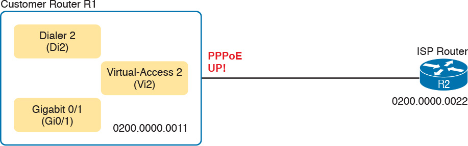
Figure 15-27 Details Found in Example 15-13 Output
Example 15-13 Connecting the Physical, Virtual-Access, Dialer, and PPPoE State
R1# show pppoe session interface gigabitEthernet 0/1
1 client session
Uniq ID PPPoE RemMAC Port VT VA State
SID LocMAC VA-st Type
N/A 1 0200.0000.0022 Gi0/1 Di2 Vi2 UP
0200.0000.0011 UP
Note that the show pppoe session command lists the same kind of information shown in Example 15-13, but for all PPPoE sessions on the router. The show pppoe session interface gigabitethernet0/1 command in the example limits the output to a message group for all PPPoE sessions off the listed interface (G0/1).
Verifying Dialer Interface Layer 3 Status
The dialer interface acts as a Layer 3 interface for the router in addition to being a configuration template for creating the virtual-access interface. So, the dialer interface should have an IP address. If learned dynamically, the address is typically learned with PPPoE, specifically by IPCP. Additionally, all routes in the IP routing table will reference the dialer interface instead of the virtual-access or Ethernet interface used by PPPoE.
In the continuing example in this section, two commands on customer router R1 confirm that the dialer has an IP address and that routes use the dialer interface. The show ip route command lists a connected route for both R1’s learned interface address of 10.1.3.2 and the neighboring ISP’s address of 10.1.3.1. PPP IPCP announces the address on the other end of the PPP link, so R1 learns R2’s IP address (10.1.3.1) and adds a connected route as shown, as shown in Example 15-14.
Example 15-14 Displaying Layer 3 Orientation of Dialer Interface
R1# show ip route
! Legend omitted for brevity
10.0.0.0/8 is variably subnetted, 4 subnets, 2 masks
C 10.1.1.0/24 is directly connected, GigabitEthernet0/2
L 10.1.1.9/32 is directly connected, GigabitEthernet0/2
C 10.1.3.1/32 is directly connected, Dialer2
C 10.1.3.2/32 is directly connected, Dialer2
R1# show ip interface brief dialer 2
Interface IP-Address OK? Method Status Protocol
Dialer2 10.1.3.2 YES IPCP up up
The second command in the example lists the one line in the show ip interface brief command output for the dialer interface. Note that it lists the address, but more importantly, it lists the method as “IPCP.” This is a confirmation that R1 learned the address through PPPoE, specifically PPP’s IPCP.
PPPoE Troubleshooting
Like many networking features, the Layer 3 features simply do not work if the Layer 2 function they rely upon has a problem. Similarly, a Layer 2 problem often cannot be noticed if the underlying Layer 1 also has problems. In most cases, if you have problems with the network, data link, and physical layers, you have to work from the lower layers up the stack to find the issues.
This troubleshooting section takes a similar approach. Trying to cover every combination of missing or incorrect PPPoE configuration, with the resulting differences in show command output, would be pretty laborious. Instead, this section takes a structured approach to rebuild the configuration shown throughout the earlier PPPoE topics, specifically as listed in Example 15-9 and repeated in Figure 15-25. By configuring a few related commands and then stopping to show and discuss the current status, you can learn about what status to expect if a configuration omits some configuration or uses the wrong parameters on some configuration.
This section builds the configuration on the dialer interface, plus on the physical interface, in three different steps, as listed here. Note that the figure organizes the configuration based on TCP/IP Layers 1, 2, and 3, as outlined earlier in Figure 15-25 (repeated here as Figure 15-28 for convenience).

Figure 15-28 PPPoE Client Configuration on Router R1 (Duplicate of Figure 15-25)
The next few topics in this chapter work through an analysis of the status of PPPoE at various stages of configuration, until the configuration is completed, based on these steps. At each step, the text makes some comments to point out the key facts about the current state.
Step 1. Add the Layer 1 configuration per Figure 15-28.
Step 2. Add the Layer 2 configuration per Figure 15-28.
Step 3. Add the Layer 3 configuration per Figure 15-28.
Step 0: Status Before Beginning the First Step
This troubleshooting scenario begins with R1 having all default configuration in relation to PPPoE, except that the configuration does begin with a few statements already on Router R1 (the customer router), as shown in Example 15-15. Note that the MAC address is set on the interface, for the sole purpose of making it easier to find in show command output. For the same reason, ISP Router R2 has been set to use MAC address 0200.0000.0022.
Example 15-15 Relevant Configuration on Customer Router (R1) at Beginning of Troubleshooting
R1# show running-config interface gigabitethernet0/1
Building configuration...
Current configuration : 202 bytes
!
interface GigabitEthernet0/1
mac-address 0200.0000.0011
no ip address
end
R1# show running-config interface Dialer2
Building configuration...
Current configuration : 55 bytes
!
interface Dialer2
no ip address
Additionally, the dialer 2 interface has been created with the interface dialer 2 command, but with no further interface configuration commands added. The reason for configuring the dialer interface first, without other configuration, is to emphasize some details about the dialer interface’s status.
The interface status of a dialer interface, before adding any configuration at all, is different than the status of most any interface on a router or switch. You could configure the dialer interface with a shutdown command, and it would have an administratively disabled line status like any other router interface. However, the dialer interface is in a no shutdown state by default.
When a dialer interface is not fully working, which is true when there are no subcommands configured on the dialer interface, both the interface and protocol status will be “up (spoofing),” as shown in Example 15-16. The show ip interface brief command will list the two status codes (the interface status and the protocol status) both as up. However, the show interfaces command lists a longer status value of up (spoofing). (Note that the show interfaces dialer 2 | include line command filters the output to list only the line with “line” in it.)
Example 15-16 Step 0: Status of Dialer 2 After Creation but with No Other Configuration
R1# show interfaces dialer 2 | include line
Dialer2 is up (spoofing), line protocol is up (spoofing)
R1# show ip interface brief dialer 2
Interface IP-Address OK? Method Status Protocol
Dialer2 unassigned YES unset up up
R1# show pppoe session
R1#
At the bottom of the output, the show pppoe session command implies that PPPoE is not working yet, because it returns no lines of output. With PPPoE working, this command lists a small group of output lines for every PPPoE session on the router.
Step 1: Status After Layer 1 Configuration
The bottom of Figure 15-28 shows commands labeled as Layer 1. This next section begins by adding those commands to the router. Specifically:
1. The dialer pool 1 command is added under the dialer interface.
2. The pppoe-client dial-pool-number 1 command is added under interface G0/1.
3. IOS automatically adds the pppoe enable command under interface G0/1.
At this point, the dialer interface has referenced a pool, and an Ethernet interface is in the pool (G0/1 in this case), so the dialer interface has a physical interface to use. Example 15-17 confirms that the dialer and physical interfaces can now work together (Layer 1), but that PPPoE (Layer 2) does not yet work. Of particular note in this case:
![]() The dialer interface state is still up (spoofing). The interface state will remain in this state until PPPoE is functional.
The dialer interface state is still up (spoofing). The interface state will remain in this state until PPPoE is functional.
![]() R1 is at least trying to create a PPPoE session because of the automatic configuration of the pppoe enable command on G0/1. Now the show pppoe session command lists some evidence of that attempt. However, if you compare the highlighted items to the working output in Example 15-12, you will see
R1 is at least trying to create a PPPoE session because of the automatic configuration of the pppoe enable command on G0/1. Now the show pppoe session command lists some evidence of that attempt. However, if you compare the highlighted items to the working output in Example 15-12, you will see
![]() The state is not up (it is PADISNT).
The state is not up (it is PADISNT).
![]() It does not list a VA (virtual-access) interface, listing instead N/A for “not applicable.”
It does not list a VA (virtual-access) interface, listing instead N/A for “not applicable.”
![]() It lists placeholders for the MAC addresses (all 0s) at this point, which are not the addresses used by the routers.
It lists placeholders for the MAC addresses (all 0s) at this point, which are not the addresses used by the routers.
Example 15-17 Status After Step 1: Layer 1 Configuration (Per Figure 15-28)
R1# show interfaces dialer 2 | include line
Dialer2 is up (spoofing), line protocol is up (spoofing)
R1# show pppoe session
1 client session
Uniq ID PPPoE RemMAC Port VT VA State
SID LocMAC VA-st Type
N/A 0 0000.0000.0000 Gi0/1 Di2 N/A PADISNT
0000.0000.0000
Also, the example does not bother to look at the Layer 3 information, like the dialer interface IP address and connected routes. Because PPPoE still does not work (Layer 2), the Layer 3 address discovery could not yet have worked either.
Step 2: Status After Layer 2 (PPP) Configuration
Per the Figure 15-28 comments about Layer 2, at this step, R1 next adds three PPP commands to the dialer interface: encapsulation ppp, ppp chap hostname Fred, and ppp chap password Barney. This new configuration completes all PPP and PPPoE configuration for R1, so the PPPoE session should work The output in Example 15-18 confirms many facts about a working PPPoE design, including:
![]() The dialer 2 interface state is up instead of up (spoofing). (The protocol state remains up (spoofing) even when all is working.)
The dialer 2 interface state is up instead of up (spoofing). (The protocol state remains up (spoofing) even when all is working.)
![]() The show pppoe session command lists a state of UP.
The show pppoe session command lists a state of UP.
![]() The show pppoe session command lists all three key interfaces: dialer 2 (Di2), virtual-access 1 (Vi1), and GigabitEthernet0/1 (Gi0/1).
The show pppoe session command lists all three key interfaces: dialer 2 (Di2), virtual-access 1 (Vi1), and GigabitEthernet0/1 (Gi0/1).
![]() The show pppoe session command lists the MAC addresses of the local and ISP router.
The show pppoe session command lists the MAC addresses of the local and ISP router.
Example 15-18 Status After Step 3: Layer 2 Configuration (Per Figure 15-28)
R1# show interfaces dialer 2 | include line
Dialer2 is up, line protocol is up (spoofing)
R1# show pppoe session interface g0/1
1 client session
Uniq ID PPPoE RemMAC Port VT VA State
SID LocMAC VA-st Type
N/A 35 0200.0000.0022 Gi0/1 Di2 Vi1 UP
0200.0000.0011 UP
Although not shown here, now that PPPoE is up, the show interfaces dialer 2 command would list two groups of messages: the first set for the dialer interface, and the second set for interface Vi1. Before the PPPoE session comes up and binds the Vi1 interface to Di2, the show interfaces dialer 2 command would list messages for dialer 2 only. (See Example 15-11 for an example of this output.)
Problems still exist. At this point, the configuration for Layers 1 and 2 has been added and the functions have been verified, but the Layer 3 configuration has not yet been added. To confirm those issues before adding the configuration, Example 15-19 shows the status of the dialer interface’s IPv4 address and the lack of associated IP routes that result. Note that the dialer interface has no IP address assigned, and there are no routes listing dialer 2 as an outgoing interface; only G0/2, an interface ignored for this lab, is listed as an outgoing interface.
Example 15-19 Layer 3 Status After Step 2, with No IP Configuration for the Dialer Interface
R1# show ip interface brief dialer 2
Interface IP-Address OK? Method Status Protocol
Dialer2 unassigned YES unset up up
R1# show ip route
! Legend omitted for brevity
10.0.0.0/8 is variably subnetted, 2 subnets, 2 masks
C 10.1.1.0/24 is directly connected, GigabitEthernet0/2
L 10.1.1.9/32 is directly connected, GigabitEthernet0/2
Step 3: Status After Layer 3 (IP) Configuration
Figure 15-28 lists three configuration commands in the Layer 3 area, with two on the dialer interface. This step adds two commands to interface dialer 2, namely the ip address negotiated and mtu 1492 commands. (The third command for Layer 3 in Figure 15-28, the no ip address command for interface G0/1, was preconfigured as noted earlier in Example 15-15.)
At this point, all should be working properly. The configuration for this troubleshooting scenario should exactly match Example 15-9 and Figure 15-28, which is the same configuration used to gather all the verification commands shown in Examples 15-11 through 15-14. Rather than repeat all those commands again, feel free to refer to those examples to review the status shown when all is working well. For the Layer 3 status, make sure and review Example 15-14, which shows the Layer 3 status on the dialer interface.
PPPoE Troubleshooting Summary
The sections about PPPoE verification and troubleshooting show a lot of command examples. This section summarizes a few suggestions for what to look for to help with review and exam preparation.
Layer 1: If the show pppoe session [interface type number] command does not list output, or does not list both the physical and dialer interfaces, check for the existence of the Layer 1 commands as noted in Figure 15-28. Check for errors in those commands as well; for instance, the dial pool numbers must match. Also check to make sure both the dialer and physical interfaces are not shut down. (See Example 15-16.)
Layer 2: If the show pppoe session [interface type number] command does list output, and lists the physical and dialer interfaces, but no Vi interface, check the Layer 2 configuration as noted in Figure 15-28. Those could be missing, or there could be mistakes. For instance, something as simple as a mistyped CHAP password ends with this result. (See Example 15-17.)
Layer 2: If the show interfaces dialer number command lists an interface status (the first status value) of up (spoofing), that is another confirmation that PPPoE is not yet working. If so, check the PPP configuration on the dialer interface, and confirm the username/password matches with what the ISP requires. (See Example 15-18.)
Layer 2: To be confident PPPoE is working, look for three items, all seen in Example 15-18’s show pppoe session command output:
![]() A status of UP
A status of UP
![]() Three interfaces listed in shorthand: the Ethernet interface (Gi0/1 in the example), the dialer interface (Di2), and the virtual-access interface (Vi1)
Three interfaces listed in shorthand: the Ethernet interface (Gi0/1 in the example), the dialer interface (Di2), and the virtual-access interface (Vi1)
![]() The MAC addresses of the two routers; check the local MAC address with a show interfaces command on the local router
The MAC addresses of the two routers; check the local MAC address with a show interfaces command on the local router
Layer 3: If the show interfaces or show ip interface brief command does not list an IP address for the dialer interface, then look for missing or incorrect Layer 3 commands per Figure 15-28.
Here are a couple of possible false positives to avoid as well:
Dialer interface status: If the show interfaces dialer number command lists a protocol status (the second status value) of up (spoofing), do not be concerned. It will always list that status, both when working and not working. (See Example 15-18.)
Physical interface IP address: The physical Ethernet interface will not have an IP address. It is used to send Ethernet frames only. So, it is appropriate with PPPoE to configure the physical Ethernet interface with the no ip address command.
Chapter Review
One key to doing well on the exams is to perform repetitive spaced review sessions. Review this chapter’s material using either the tools in the book, DVD, or interactive tools for the same material found on the book’s companion website. Refer to the “Your Study Plan” element for more details. Table 15-2 outlines the key review elements and where you can find them. To better track your study progress, record when you completed these activities in the second column.

Review All the Key Topics

Key Terms You Should Know
generic routing encapsulation (GRE)
Cisco AnyConnect Secure Mobility Client
Dynamic Multipoint VPN (DMVPN)
Next Hop Resolution Protocol (NHRP)
Command References
Tables 15-4 and 15-5 list configuration and verification commands used in this chapter. As an easy review exercise, cover the left column in a table, read the right column, and try to recall the command without looking. Then repeat the exercise, covering the right column, and try to recall what the command does.


Table 15-5 Chapter 15 EXEC Command Reference