
Chapter 1. Implementing Ethernet Virtual LANs
This chapter covers the following exam topics:
1.0 LAN Switching Technologies
1.1 Configure, verify, and troubleshoot VLANs (normal/extended range) spanning multiple switches
1.1.a Access ports (data and voice)
1.1.b Default VLAN
1.2 Configure, verify, and troubleshoot interswitch connectivity
1.2.a Add and remove VLANs on a trunk
1.2.b DTP and VTP (v1&v2)
Virtual LANs (VLAN) have an impact on many parts of a switch’s logic. Frame forwarding happens per VLAN. MAC learning adds MAC table entries, and those entries include the associated VLAN. Even Spanning Tree Protocol (STP), a big focus in Part I of this book, often happens per-VLAN.
This chapter examines how many switch core features work in the context of VLANs. The chapter breaks the topics into concepts in the first section of the chapter, with configuration and verification in the second half. The topics include VLANs, VLAN trunking, routing between VLANs, plus voice and data VLANs. (Chapter 4, “LAN Troubleshooting,” revisits some of these topics from a troubleshooting perspective.)
For you ICND1 Cert Guide readers, note that this chapter is identical to the ICND1 100-105 Cert Guide’s Chapter 11. Both the ICND1 and ICND2 exams include specific exam topics about most of the content in this chapter. By using the exact same chapter for duplicate exam topics between the two books, hopefully those of you who remember a lot about these topics can move quickly through this chapter. For those who do not remember as much, just treat it as a normal chapter.
“Do I Know This Already?” Quiz
Take the quiz (either here, or use the PCPT software) if you want to use the score to help you decide how much time to spend on this chapter. The answers are at the bottom of the page following the quiz, and the explanations are in DVD Appendix C and in the PCPT software.

1. In a LAN, which of the following terms best equates to the term VLAN?
a. Collision domain
b. Broadcast domain
c. Subnet
d. Single switch
e. Trunk
2. Imagine a switch with three configured VLANs. How many IP subnets are required, assuming that all hosts in all VLANs want to use TCP/IP?
a. 0
b. 1
c. 2
d. 3
e. You cannot tell from the information provided.
3. Switch SW1 sends a frame to switch SW2 using 802.1Q trunking. Which of the answers describes how SW1 changes or adds to the Ethernet frame before forwarding the frame to SW2?
a. Inserts a 4-byte header and does change the MAC addresses
b. Inserts a 4-byte header and does not change the MAC addresses
c. Encapsulates the original frame behind an entirely new Ethernet header
d. None of the other answers are correct.
4. Imagine that you are told that switch 1 is configured with the dynamic auto parameter for trunking on its Fa0/5 interface, which is connected to switch 2. You have to configure switch 2. Which of the following settings for trunking could allow trunking to work? (Choose two answers.)
a. on
b. dynamic auto
c. dynamic desirable
d. access
5. A switch has just arrived from Cisco. The switch has never been configured with any VLANs, but VTP has been disabled. An engineer gets into configuration mode and issues the vlan 22 command, followed by the name Hannahs-VLAN command. Which of the following are true? (Choose two answers.)
a. VLAN 22 is listed in the output of the show vlan brief command.
b. VLAN 22 is listed in the output of the show running-config command.
c. VLAN 22 is not created by this process.
d. VLAN 22 does not exist in that switch until at least one interface is assigned to that VLAN.
6. Which of the following commands identify switch interfaces as being trunking interfaces: interfaces that currently operate as VLAN trunks? (Choose two answers.)
a. show interfaces
b. show interfaces switchport
c. show interfaces trunk
d. show trunks
Answers to the “Do I Know This Already?” quiz:
1 B 2 D 3 B 4 A, C 5 A, B 6 B, C
Foundation Topics
Virtual LAN Concepts
Before understanding VLANs, you must first have a specific understanding of the definition of a LAN. For example, from one perspective, a LAN includes all the user devices, servers, switches, routers, cables, and wireless access points in one location. However, an alternative narrower definition of a LAN can help in understanding the concept of a virtual LAN:
A LAN includes all devices in the same broadcast domain.
A broadcast domain includes the set of all LAN-connected devices, so that when any of the devices sends a broadcast frame, all the other devices get a copy of the frame. So, from one perspective, you can think of a LAN and a broadcast domain as being basically the same thing.
Without VLANs, a switch considers all its interfaces to be in the same broadcast domain. That is, for one switch, when a broadcast frame entered one switch port, the switch forwarded that broadcast frame out all other ports. With that logic, to create two different LAN broadcast domains, you had to buy two different Ethernet LAN switches, as shown in Figure 1-1.

With support for VLANs, a single switch can accomplish the same goals of the design in Figure 1-1—to create two broadcast domains—with a single switch. With VLANs, a switch can configure some interfaces into one broadcast domain and some into another, creating multiple broadcast domains. These individual broadcast domains created by the switch are called virtual LANs (VLAN).
For example, in Figure 1-2, the single switch creates two VLANs, treating the ports in each VLAN as being completely separate. The switch would never forward a frame sent by Dino (in VLAN 1) over to either Wilma or Betty (in VLAN 2).

Designing campus LANs to use more VLANs, each with a smaller number of devices, often helps improve the LAN in many ways. For example, a broadcast sent by one host in a VLAN will be received and processed by all the other hosts in the VLAN—but not by hosts in a different VLAN. Limiting the number of hosts that receive a single broadcast frame reduces the number of hosts that waste effort processing unneeded broadcasts. It also reduces security risks, because fewer hosts see frames sent by any one host. These are just a few reasons for separating hosts into different VLANs. The following list summarizes the most common reasons for choosing to create smaller broadcast domains (VLANs):

![]() To reduce CPU overhead on each device by reducing the number of devices that receive each broadcast frame
To reduce CPU overhead on each device by reducing the number of devices that receive each broadcast frame
![]() To reduce security risks by reducing the number of hosts that receive copies of frames that the switches flood (broadcasts, multicasts, and unknown unicasts)
To reduce security risks by reducing the number of hosts that receive copies of frames that the switches flood (broadcasts, multicasts, and unknown unicasts)
![]() To improve security for hosts that send sensitive data by keeping those hosts on a separate VLAN
To improve security for hosts that send sensitive data by keeping those hosts on a separate VLAN
![]() To create more flexible designs that group users by department, or by groups that work together, instead of by physical location
To create more flexible designs that group users by department, or by groups that work together, instead of by physical location
![]() To solve problems more quickly, because the failure domain for many problems is the same set of devices as those in the same broadcast domain
To solve problems more quickly, because the failure domain for many problems is the same set of devices as those in the same broadcast domain
![]() To reduce the workload for the Spanning Tree Protocol (STP) by limiting a VLAN to a single access switch
To reduce the workload for the Spanning Tree Protocol (STP) by limiting a VLAN to a single access switch
This chapter does not examine all the reasons for VLANs in more depth. However, know that most enterprise networks use VLANs quite a bit. The rest of this chapter looks closely at the mechanics of how VLANs work across multiple Cisco switches, including the required configuration. To that end, the next section examines VLAN trunking, a feature required when installing a VLAN that exists on more than one LAN switch.
Creating Multiswitch VLANs Using Trunking
Configuring VLANs on a single switch requires only a little effort: You simply configure each port to tell it the VLAN number to which the port belongs. With multiple switches, you have to consider additional concepts about how to forward traffic between the switches.
When using VLANs in networks that have multiple interconnected switches, the switches need to use VLAN trunking on the links between the switches. VLAN trunking causes the switches to use a process called VLAN tagging, by which the sending switch adds another header to the frame before sending it over the trunk. This extra trunking header includes a VLAN identifier (VLAN ID) field so that the sending switch can associate the frame with a particular VLAN ID, and the receiving switch can then know in what VLAN each frame belongs.
Figure 1-3 shows an example that demonstrates VLANs that exist on multiple switches, but it does not use trunking. First, the design uses two VLANs: VLAN 10 and VLAN 20. Each switch has two ports assigned to each VLAN, so each VLAN exists in both switches. To forward traffic in VLAN 10 between the two switches, the design includes a link between switches, with that link fully inside VLAN 10. Likewise, to support VLAN 20 traffic between switches, the design uses a second link between switches, with that link inside VLAN 20.

The design in Figure 1-3 functions perfectly. For example, PC11 (in VLAN 10) can send a frame to PC14. The frame flows into SW1, over the top link (the one that is in VLAN 10) and over to SW2.
The design shown in Figure 1-3 works, but it simply does not scale very well. It requires one physical link between switches to support every VLAN. If a design needed 10 or 20 VLANs, you would need 10 or 20 links between switches, and you would use 10 or 20 switch ports (on each switch) for those links.
VLAN Tagging Concepts
VLAN trunking creates one link between switches that supports as many VLANs as you need. As a VLAN trunk, the switches treat the link as if it were a part of all the VLANs. At the same time, the trunk keeps the VLAN traffic separate, so frames in VLAN 10 would not go to devices in VLAN 20, and vice versa, because each frame is identified by VLAN number as it crosses the trunk. Figure 1-4 shows the idea, with a single physical link between the two switches.

The use of trunking allows switches to pass frames from multiple VLANs over a single physical connection by adding a small header to the Ethernet frame. For example, Figure 1-5 shows PC11 sending a broadcast frame on interface Fa0/1 at Step 1. To flood the frame, switch SW1 needs to forward the broadcast frame to switch SW2. However, SW1 needs to let SW2 know that the frame is part of VLAN 10, so that after the frame is received, SW2 will flood the frame only into VLAN 10, and not into VLAN 20. So, as shown at Step 2, before sending the frame, SW1 adds a VLAN header to the original Ethernet frame, with the VLAN header listing a VLAN ID of 10 in this case.

When SW2 receives the frame, it understands that the frame is in VLAN 10. SW2 then removes the VLAN header, forwarding the original frame out its interfaces in VLAN 10 (Step 3).
For another example, consider the case when PC21 (in VLAN 20) sends a broadcast. SW1 sends the broadcast out port Fa0/4 (because that port is in VLAN 20) and out Gi0/1 (because it is a trunk, meaning that it supports multiple different VLANs). SW1 adds a trunking header to the frame, listing a VLAN ID of 20. SW2 strips off the trunking header after determining that the frame is part of VLAN 20, so SW2 knows to forward the frame out only ports Fa0/3 and Fa0/4, because they are in VLAN 20, and not out ports Fa0/1 and Fa0/2, because they are in VLAN 10.
The 802.1Q and ISL VLAN Trunking Protocols
Cisco has supported two different trunking protocols over the years: Inter-Switch Link (ISL) and IEEE 802.1Q. Cisco created ISL long before 802.1Q, in part because the IEEE had not yet defined a VLAN trunking standard. Years later, the IEEE completed work on the 802.1Q standard, which defines a different way to do trunking. Today, 802.1Q has become the more popular trunking protocol, with Cisco not even supporting ISL in some of its newer models of LAN switches, including the 2960 switches used in the examples in this book.
While both ISL and 802.1Q tag each frame with the VLAN ID, the details differ. 802.1Q inserts an extra 4-byte 802.1Q VLAN header into the original frame’s Ethernet header, as shown at the top of Figure 1-6. As for the fields in the 802.1Q header, only the 12-bit VLAN ID field inside the 802.1Q header matters for topics discussed in this book. This 12-bit field supports a theoretical maximum of 212 (4096) VLANs, but in practice it supports a maximum of 4094. (Both 802.1Q and ISL use 12 bits to tag the VLAN ID, with two reserved values [0 and 4095].)

Cisco switches break the range of VLAN IDs (1–4094) into two ranges: the normal range and the extended range. All switches can use normal-range VLANs with values from 1 to 1005. Only some switches can use extended-range VLANs with VLAN IDs from 1006 to 4094. The rules for which switches can use extended-range VLANs depend on the configuration of the VLAN Trunking Protocol (VTP), which is discussed briefly in the section “VLAN Trunking Configuration,” later in this chapter.
802.1Q also defines one special VLAN ID on each trunk as the native VLAN (defaulting to use VLAN 1). By definition, 802.1Q simply does not add an 802.1Q header to frames in the native VLAN. When the switch on the other side of the trunk receives a frame that does not have an 802.1Q header, the receiving switch knows that the frame is part of the native VLAN. Note that because of this behavior, both switches must agree on which VLAN is the native VLAN.
The 802.1Q native VLAN provides some interesting functions, mainly to support connections to devices that do not understand trunking. For example, a Cisco switch could be cabled to a switch that does not understand 802.1Q trunking. The Cisco switch could send frames in the native VLAN—meaning that the frame has no trunking header—so that the other switch would understand the frame. The native VLAN concept gives switches the capability of at least passing traffic in one VLAN (the native VLAN), which can allow some basic functions, like reachability to telnet into a switch.
Forwarding Data Between VLANs
If you create a campus LAN that contains many VLANs, you typically still need all devices to be able to send data to all other devices. This next topic discusses some concepts about how to route data between those VLANs.
First, it helps to know a few terms about some categories of LAN switches. All the Ethernet switch functions described in the ICND1 Cert Guide use the details and logic defined by OSI Layer 2 protocols. For example, many chapters of the ICND1 Cert Guide discussed how LAN switches receive Ethernet frames (a Layer 2 concept), look at the destination Ethernet MAC address (a Layer 2 address), and forward the Ethernet frame out some other interface. This chapter has already discussed the concept of VLANs as broadcast domains, which is yet another Layer 2 concept.
While some LAN switches work just as described in the ICND1 Cert Guide, some LAN switches have even more functions. LAN switches that forward data based on Layer 2 logic often go by the name Layer 2 switch. However, some other switches can do some functions like a router, using additional logic defined by Layer 3 protocols. These switches go by the name multilayer switch, or Layer 3 switch. This section first discusses how to forward data between VLANs when using Layer 2 switches and ends with a brief discussion of how to use Layer 3 switches.
Routing Packets Between VLANs with a Router
When including VLANs in a campus LAN design, the devices in a VLAN need to be in the same subnet. Following the same design logic, devices in different VLANs need to be in different subnets. For example, in Figure 1-7, the two PCs on the left sit in VLAN 10, in subnet 10. The two PCs on the right sit in a different VLAN (20), with a different subnet (20).

Note
The figure refers to subnets somewhat generally, like “subnet 10,” just so the subnet numbers do not distract. Also, note that the subnet numbers do not have to be the same number as the VLAN numbers.
Figure 1-7 shows the switch as if it were two switches broken in two to emphasize the point that Layer 2 switches will not forward data between two VLANs. When configured with some ports in VLAN 10 and others in VLAN 20, the switch acts like two separate switches in which it will forward traffic. In fact, one goal of VLANs is to separate traffic in one VLAN from another, preventing frames in one VLAN from leaking over to other VLANs. For example, when Dino (in VLAN 10) sends any Ethernet frame, if SW1 is a Layer 2 switch, that switch will not forward the frame to the PCs on the right in VLAN 20.
The network as a whole needs to support traffic flowing into and out of each VLAN, even though the Layer 2 switch does not forward frames outside a VLAN. The job of forwarding data into and out of a VLAN falls to routers. Instead of switching Layer 2 Ethernet frames between the two VLANs, the network must route Layer 3 packets between the two subnets.
That previous paragraph has some very specific wording related to Layers 2 and 3, so take a moment to reread and reconsider it for a moment. The Layer 2 logic does not let the Layer 2 switch forward the Layer 2 protocol data unit (L2PDU), the Ethernet frame, between VLANs. However, routers can route Layer 3 PDUs (L3PDU), packets, between subnets as their normal job in life.
For example, Figure 1-8 shows a router that can route packets between subnets 10 and 20. The figure shows the same Layer 2 switch as shown in Figure 1-7, with the same perspective of the switch being split into parts with two different VLANs, and with the same PCs in the same VLANs and subnets. Now Router R1 has one LAN physical interface connected to the switch and assigned to VLAN 10, and a second physical interface connected to the switch and assigned to VLAN 20. With an interface connected to each subnet, the Layer 2 switch can keep doing its job—forwarding frames inside a VLAN, while the router can do its job—routing IP packets between the subnets.

The figure shows an IP packet being routed from Fred, which sits in one VLAN/subnet, to Betty, which sits in the other. The Layer 2 switch forwards two different Layer 2 Ethernet frames: one in VLAN 10, from Fred to R1’s F0/0 interface, and the other in VLAN 20, from R1’s F0/1 interface to Betty. From a Layer 3 perspective, Fred sends the IP packet to its default router (R1), and R1 routes the packet out another interface (F0/1) into another subnet where Betty resides.
While the design shown in Figure 1-8 works, it uses too many physical interfaces, one per VLAN. A much less expensive (and much preferred) option uses a VLAN trunk between the switch and router, requiring only one physical link between the router and switch, while supporting all VLANs. Trunking can work between any two devices that choose to support it: between two switches, between a router and a switch, or even between server hardware and a switch.
Figure 1-9 shows the same design idea as Figure 1-8, with the same packet being sent from Fred to Betty, except now R1 uses VLAN trunking instead of a separate link for each VLAN.

Note
Because the router has a single physical link connected to the LAN switch, this design is sometimes called a router-on-a-stick.
As a brief aside about terminology, many people describe the concept in Figures 1-8 and 1-9 as “routing packets between VLANs.” You can use that phrase, and people know what you mean. However, note that this phrase is not literally true, because it refers to routing packets (a Layer 3 concept) and VLANs (a Layer 2 concept). It just takes fewer words to say something like “routing between VLANs” rather than the literally true but long “routing Layer 3 packets between Layer 3 subnets, with those subnets each mapping to a Layer 2 VLAN.”
Routing Packets with a Layer 3 Switch
Routing packets using a physical router, even with the VLAN trunk in the router-on-a-stick model shown in Figure 1-9, still has one significant problem: performance. The physical link puts an upper limit on how many bits can be routed, and less expensive routers tend to be less powerful, and might not be able to route a large enough number of packets per second (pps) to keep up with the traffic volumes.
The ultimate solution moves the routing functions inside the LAN switch hardware. Vendors long ago started combining the hardware and software features of their Layer 2 LAN switches, plus their Layer 3 routers, creating products called Layer 3 switches (also known as multilayer switches). Layer 3 switches can be configured to act only as a Layer 2 switch, or they can be configured to do both Layer 2 switching as well as Layer 3 routing.
Today, many medium- to large-sized enterprise campus LANs use Layer 3 switches to route packets between subnets (VLANs) in a campus.
In concept, a Layer 3 switch works a lot like the original two devices on which the Layer 3 switch is based: a Layer 2 LAN switch and a Layer 3 router. In fact, if you take the concepts and packet flow shown in Figure 1-8, with a separate Layer 2 switch and Layer 3 router, and then imagine all those features happening inside one device, you have the general idea of what a Layer 3 switch does. Figure 1-10 shows that exact concept, repeating many details of Figure 1-8, but with an overlay that shows the one Layer 3 switch doing the Layer 2 switch functions and the separate Layer 3 routing function.

This chapter introduces the core concepts of routing IP packets between VLANs (or more accurately, between the subnets on the VLANs). Chapter 19, “IPv4 Routing in the LAN,” shows how to configure designs that use an external router with router-on-a-stick. This chapter now turns its attention to configuration and verification tasks for VLANs and VLAN trunks.
VLAN and VLAN Trunking Configuration and Verification
Cisco switches do not require any configuration to work. You can purchase Cisco switches, install devices with the correct cabling, turn on the switches, and they work. You would never need to configure the switch, and it would work fine, even if you interconnected switches, until you needed more than one VLAN. But if you want to use VLANs—and most enterprise networks do—you need to add some configuration.
This chapter separates the VLAN configuration details into two major sections. The first section looks at how to configure access interfaces, which are switch interfaces that do not use VLAN trunking. The second part shows how to configure interfaces that do use VLAN trunking.
Creating VLANs and Assigning Access VLANs to an Interface
This section shows how to create a VLAN, give the VLAN a name, and assign interfaces to a VLAN. To focus on these basic details, this section shows examples using a single switch, so VLAN trunking is not needed.
For a Cisco switch to forward frames in a particular VLAN, the switch must be configured to believe that the VLAN exists. In addition, the switch must have nontrunking interfaces (called access interfaces) assigned to the VLAN, and/or trunks that support the VLAN. The configuration steps for access interfaces are as follows, with the trunk configuration shown later in the section “VLAN Trunking Configuration”:
Step 1. To configure a new VLAN, follow these steps:
A. From configuration mode, use the vlan vlan-id command in global configuration mode to create the VLAN and to move the user into VLAN configuration mode.
B. (Optional) Use the name name command in VLAN configuration mode to list a name for the VLAN. If not configured, the VLAN name is VLANZZZZ, where ZZZZ is the four-digit decimal VLAN ID.
Step 2. For each access interface (each interface that does not trunk, but instead belongs to a single VLAN), follow these steps:
A. Use the interface type number command in global configuration mode to move into interface configuration mode for each desired interface.
B. Use the switchport access vlan id-number command in interface configuration mode to specify the VLAN number associated with that interface.
C. (Optional) Use the switchport mode access command in interface configuration mode to make this port always operate in access mode (that is, to not trunk).
While the list might look a little daunting, the process on a single switch is actually pretty simple. For example, if you want to put the switch’s ports in three VLANs—11, 12, and 13—you just add three vlan commands: vlan 11, vlan 12, and vlan 13. Then, for each interface, add a switchport access vlan 11 (or 12 or 13) command to assign that interface to the proper VLAN.
Note
The term default VLAN (as shown in the exam topics) refers to the default setting on the switchport access vlan vlan-id command, and that default is VLAN ID 1. In other words, by default, each port is assigned to access VLAN 1.
VLAN Configuration Example 1: Full VLAN Configuration
Example 1-1 shows the configuration process of adding a new VLAN and assigning access interfaces to that VLAN. Figure 1-11 shows the network used in the example, with one LAN switch (SW1) and two hosts in each of three VLANs (1, 2, and 3). The example shows the details of the two-step process for VLAN 2 and the interfaces in VLAN 2, with the configuration of VLAN 3 deferred until the next example.

Example 1-1 Configuring VLANs and Assigning VLANs to Interfaces
SW1# show vlan brief
VLAN Name Status Ports
---- -------------------------------- --------- -------------------------------
1 default active Fa0/1, Fa0/2, Fa0/3, Fa0/4
Fa0/5, Fa0/6, Fa0/7, Fa0/8
Fa0/9, Fa0/10, Fa0/11, Fa0/12
Fa0/13, Fa0/14, Fa0/15, Fa0/16
Fa0/17, Fa0/18, Fa0/19, Fa0/20
Fa0/21, Fa0/22, Fa0/23, Fa0/24
Gi0/1, Gi0/2
1002 fddi-default act/unsup
1003 token-ring-default act/unsup
1004 fddinet-default act/unsup
1005 trnet-default act/unsup
! Above, VLANs 2 and 3 do not yet exist. Below, VLAN 2 is added, with name Freds-vlan,
! with two interfaces assigned to VLAN 2.
SW1# configure terminal
Enter configuration commands, one per line. End with CNTL/Z.
SW1(config)# vlan 2
SW1(config-vlan)# name Freds-vlan
SW1(config-vlan)# exit
SW1(config)# interface range fastethernet 0/13 - 14
SW1(config-if)# switchport access vlan 2
SW1(config-if)# switchport mode access
SW1(config-if)# end
! Below, the show running-config command lists the interface subcommands on
! interfaces Fa0/13 and Fa0/14.
SW1# show running-config
! Many lines omitted for brevity
! Early in the output:
vlan 2
name Freds-vlan
!
! more lines omitted for brevity
interface FastEthernet0/13
switchport access vlan 2
switchport mode access
!
interface FastEthernet0/14
switchport access vlan 2
switchport mode access
!
SW1# show vlan brief
VLAN Name Status Ports
---- -------------------------------- --------- -------------------------------
1 default active Fa0/1, Fa0/2, Fa0/3, Fa0/4
Fa0/5, Fa0/6, Fa0/7, Fa0/8
Fa0/9, Fa0/10, Fa0/11, Fa0/12
Fa0/15, Fa0/16, Fa0/17, Fa0/18
Fa0/19, Fa0/20, Fa0/21, Fa0/22
Fa0/23, Fa0/24, Gi0/1, Gi0/2
2 Freds-vlan active Fa0/13, Fa0/14
1002 fddi-default act/unsup
1003 token-ring-default act/unsup
1004 fddinet-default act/unsup
1005 trnet-default act/unsup
SW1# show vlan id 2
VLAN Name Status Ports
---- -------------------------------- --------- -------------------------------
2 Freds-vlan active Fa0/13, Fa0/14
VLAN Type SAID MTU Parent RingNo BridgeNo Stp BrdgMode Trans1 Trans2
---- ----- ---------- ----- ------ ------ -------- ---- -------- ------ ------
2 enet 100010 1500 - - - - - 0 0
Remote SPAN VLAN
----------------
Disabled
Primary Secondary Type Ports
------- --------- ----------------- ------------------------------------------
The example begins with the show vlan brief command, confirming the default settings of five nondeletable VLANs, with all interfaces assigned to VLAN 1. (VLAN 1 cannot be deleted, but can be used. VLANs 1002–1005 cannot be deleted and cannot be used as access VLANs today.) In particular, note that this 2960 switch has 24 Fast Ethernet ports (Fa0/1–Fa0/24) and two Gigabit Ethernet ports (Gi0/1 and Gi0/2), all of which are listed as being in VLAN 1 per that first command’s output.
Next, the example shows the process of creating VLAN 2 and assigning interfaces Fa0/13 and Fa0/14 to VLAN 2. Note in particular that the example uses the interface range command, which causes the switchport access vlan 2 interface subcommand to be applied to both interfaces in the range, as confirmed in the show running-config command output at the end of the example.
After the configuration has been added, to list the new VLAN, the example repeats the show vlan brief command. Note that this command lists VLAN 2, name Freds-vlan, and the interfaces assigned to that VLAN (Fa0/13 and Fa0/14). The show vlan id 2 command that follows then confirms that ports Fa0/13 and Fa0/14 are assigned to VLAN 2.
The example surrounding Figure 1-11 uses six switch ports, all of which need to operate as access ports. That is, each port should not use trunking, but instead should be assigned to a single VLAN, as assigned by the switchport access vlan vlan-id command. However, as configured in Example 1-1, these interfaces could negotiate to later become trunk ports, because the switch defaults to allow the port to negotiate trunking and decide whether to act as an access interface or as a trunk interface.
For ports that should always act as access ports, add the optional interface subcommand switchport mode access. This command tells the switch to only allow the interface to be an access interface. The upcoming section “VLAN Trunking Configuration” discusses more details about the commands that allow a port to negotiate whether it should use trunking.
Note
The book includes a video that works through a different VLAN configuration example as well. You can find the video on the DVD and on the companion website.
VLAN Configuration Example 2: Shorter VLAN Configuration
Example 1-1 shows several of the optional configuration commands, with a side effect of being a bit longer than is required. Example 1-2 shows a much briefer alternative configuration, picking up the story where Example 1-1 ended and showing the addition of VLAN 3 (as shown in Figure 1-11). Note that SW1 does not know about VLAN 3 at the beginning of this example.
Example 1-2 Shorter VLAN Configuration Example (VLAN 3)
SW1# configure terminal
Enter configuration commands, one per line. End with CNTL/Z.
SW1(config)# interface range Fastethernet 0/15 - 16
SW1(config-if-range)# switchport access vlan 3
% Access VLAN does not exist. Creating vlan 3
SW1(config-if-range)# ^Z
SW1# show vlan brief
VLAN Name Status Ports
---- -------------------------------- --------- -------------------------------
1 default active Fa0/1, Fa0/2, Fa0/3, Fa0/4
Fa0/5, Fa0/6, Fa0/7, Fa0/8
Fa0/9, Fa0/10, Fa0/11, Fa0/12
Fa0/17, Fa0/18, Fa0/19, Fa0/20
Fa0/21, Fa0/22, Fa0/23, Fa0/24
Gi0/1, Gi0/2
2 Freds-vlan active Fa0/13, Fa0/14
3 VLAN0003 active Fa0/15, Fa0/16
1002 fddi-default act/unsup
1003 token-ring-default act/unsup
1004 fddinet-default act/unsup
1005 trnet-default act/unsup
Example 1-2 shows how a switch can dynamically create a VLAN—the equivalent of the vlan vlan-id global config command—when the switchport access vlan interface subcommand refers to a currently unconfigured VLAN. This example begins with SW1 not knowing about VLAN 3. When the switchport access vlan 3 interface subcommand was used, the switch realized that VLAN 3 did not exist, and as noted in the shaded message in the example, the switch created VLAN 3, using a default name (VLAN0003). No other steps are required to create the VLAN. At the end of the process, VLAN 3 exists in the switch, and interfaces Fa0/15 and Fa0/16 are in VLAN 3, as noted in the shaded part of the show vlan brief command output.
VLAN Trunking Protocol
Before showing more configuration examples, you also need to know something about a Cisco protocol and tool called the VLAN Trunking Protocol (VTP). VTP is a Cisco proprietary tool on Cisco switches that advertises each VLAN configured in one switch (with the vlan number command) so that all the other switches in the campus learn about that VLAN. However, for various reasons, many enterprises choose not to use VTP.
Each switch can use one of three VTP modes: server, client, or transparent. Switches use either VTP server or client mode when the switch wants to use VTP for its intended purpose of dynamically advertising VLAN configuration information. However, with many Cisco switches and IOS versions, VTP cannot be completely disabled on a Cisco switch; instead, the switch disables VTP by using VTP transparent mode.
Chapter 5, “VLAN Trunking Protocol,” discusses how to make use of VTP. Chapters 1 through 4 mostly ignore VTP. To that end, all examples in this book use switches that have been set either to use VTP transparent mode (with the vtp mode transparent global command) or to disable it (with the vtp mode off global command). Both options allow the administrator to configure both standard- and extended-range VLANs, and the switch lists the vlan commands in the running-config file.
Finally, on a practical note, if you happen to do lab exercises with real switches or with simulators, and you see unusual results with VLANs, check the VTP status with the show vtp status command. If your switch uses VTP server or client mode, you will find:
![]() The server switches can configure VLANs in the standard range only (1–1005).
The server switches can configure VLANs in the standard range only (1–1005).
![]() The client switches cannot configure VLANs.
The client switches cannot configure VLANs.
![]() Both servers and clients may be learning new VLANs from other switches, and seeing their VLANs deleted by other switches, because of VTP.
Both servers and clients may be learning new VLANs from other switches, and seeing their VLANs deleted by other switches, because of VTP.
![]() The show running-config command does not list any vlan commands.
The show running-config command does not list any vlan commands.
If possible in lab, switch to VTP transparent mode and ignore VTP for your switch configuration practice until you are ready to focus on how VTP works when studying for the ICND2 exam topics.
Note
Do not change VTP settings on any switch that also connects to the production network until you know how VTP works as explained in Chapter 5.
VLAN Trunking Configuration
Trunking configuration between two Cisco switches can be very simple if you just statically configure trunking. For example, if two Cisco 2960 switches connect to each other, they support only 802.1Q and not ISL. You could literally add one interface subcommand for the switch interface on each side of the link (switchport mode trunk), and you would create a VLAN trunk that supported all the VLANs known to each switch.
However, trunking configuration on Cisco switches includes many more options, including several options for dynamically negotiating various trunking settings. The configuration can either predefine different settings or tell the switch to negotiate the settings, as follows:
![]() The type of trunking: IEEE 802.1Q, ISL, or negotiate which one to use
The type of trunking: IEEE 802.1Q, ISL, or negotiate which one to use
![]() The administrative mode: Whether to always trunk, always not trunk, or negotiate
The administrative mode: Whether to always trunk, always not trunk, or negotiate
First, consider the type of trunking. Cisco switches that support ISL and 802.1Q can negotiate which type to use, using the Dynamic Trunking Protocol (DTP). If both switches support both protocols, they use ISL; otherwise, they use the protocol that both support. Today, many Cisco switches do not support the older ISL trunking protocol. Switches that support both types of trunking use the switchport trunk encapsulation {dot1q | isl | negotiate} interface subcommand to either configure the type or allow DTP to negotiate the type.
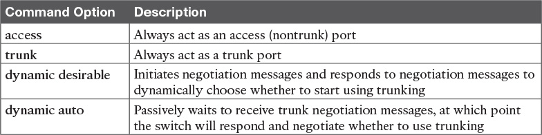
DTP can also negotiate whether the two devices on the link agree to trunk at all, as guided by the local switch port’s administrative mode. The administrative mode refers to the configuration setting for whether trunking should be used. Each interface also has an operational mode, which refers to what is currently happening on the interface, and might have been chosen by DTP’s negotiation with the other device. Cisco switches use the switchport mode interface subcommand to define the administrative trunking mode, as listed in Table 1-2.
For example, consider the two switches shown in Figure 1-12. This figure shows an expansion of the network shown in Figure 1-11, with a trunk to a new switch (SW2) and with parts of VLANs 1 and 3 on ports attached to SW2. The two switches use a Gigabit Ethernet link for the trunk. In this case, the trunk does not dynamically form by default, because both (2960) switches default to an administrative mode of dynamic auto, meaning that neither switch initiates the trunk negotiation process. By changing one switch to use dynamic desirable mode, which does initiate the negotiation, the switches negotiate to use trunking, specifically 802.1Q because the 2960s support only 802.1Q.

Example 1-3 begins by showing the two switches in Figure 1-12 with the default configuration so that the two switches do not trunk.
Example 1-3 Initial (Default) State: Not Trunking Between SW1 and SW2
SW1# show interfaces gigabit 0/1 switchport
Name: Gi0/1
Switchport: Enabled
Administrative Mode: dynamic auto
Operational Mode: static access
Administrative Trunking Encapsulation: dot1q
Operational Trunking Encapsulation: native
Negotiation of Trunking: On
Access Mode VLAN: 1 (default)
Trunking Native Mode VLAN: 1 (default)
Administrative Native VLAN tagging: enabled
Voice VLAN: none
Access Mode VLAN: 1 (default)
Trunking Native Mode VLAN: 1 (default)
Administrative Native VLAN tagging: enabled
Voice VLAN: none
Administrative private-vlan host-association: none
Administrative private-vlan mapping: none
Administrative private-vlan trunk native VLAN: none
Administrative private-vlan trunk Native VLAN tagging: enabled
Administrative private-vlan trunk encapsulation: dot1q
Administrative private-vlan trunk normal VLANs: none
Administrative private-vlan trunk private VLANs: none
Operational private-vlan: none
Trunking VLANs Enabled: ALL
Pruning VLANs Enabled: 2-1001
Capture Mode Disabled
Capture VLANs Allowed: ALL
Protected: false
Unknown unicast blocked: disabled
Unknown multicast blocked: disabled
Appliance trust: none
! Note that the next command results in a single empty line of output.
SW1# show interfaces trunk
SW1#
First, focus on the highlighted items from the output of the show interfaces switchport command at the beginning of Example 1-3. The output lists the default administrative mode setting of dynamic auto. Because SW2 also defaults to dynamic auto, the command lists SW1’s operational status as “access,” meaning that it is not trunking. (“Dynamic auto” tells both switches to sit there and wait on the other switch to start the negotiations.) The third shaded line points out the only supported type of trunking (802.1Q) on this 2960 switch. (On a switch that supports both ISL and 802.1Q, this value would by default list “negotiate,” to mean that the type of encapsulation is negotiated.) Finally, the operational trunking type is listed as “native,” which is a reference to the 802.1Q native VLAN.
The end of the example shows the output of the show interfaces trunk command, but with no output. This command lists information about all interfaces that currently operationally trunk; that is, it lists interfaces that currently use VLAN trunking. With no interfaces listed, this command also confirms that the link between switches is not trunking.
Next, consider Example 1-4, which shows the new configuration that enables trunking. In this case, SW1 is configured with the switchport mode dynamic desirable command, which asks the switch to both negotiate as well as to begin the negotiation process, rather than waiting on the other device. As soon as the command is issued, log messages appear showing that the interface goes down and then back up again, which happens when the interface transitions from access mode to trunk mode.
Example 1-4 SW1 Changes from Dynamic Auto to Dynamic Desirable
SW1# configure terminal
Enter configuration commands, one per line. End with CNTL/Z.
SW1(config)# interface gigabit 0/1
SW1(config-if)# switchport mode dynamic desirable
SW1(config-if)# ^Z
SW1#
%LINEPROTO-5-UPDOWN: Line protocol on Interface GigabitEthernet0/1, changed state to
down
%LINEPROTO-5-UPDOWN: Line protocol on Interface GigabitEthernet0/1, changed state to
up
SW1# show interfaces gigabit 0/1 switchport
Name: Gi0/1
Switchport: Enabled
Administrative Mode: dynamic desirable
Operational Mode: trunk
Administrative Trunking Encapsulation: dot1q
Operational Trunking Encapsulation: dot1q
Negotiation of Trunking: On
Access Mode VLAN: 1 (default)
Trunking Native Mode VLAN: 1 (default)
! lines omitted for brevity
! The next command formerly listed a single empty line of output; now it lists
! information about the 1 operational trunk.
SW1# show interfaces trunk
Port Mode Encapsulation Status Native vlan
Gi0/1 desirable 802.1q trunking 1
Port Vlans allowed on trunk
Gi0/1 1-4094
Port Vlans allowed and active in management domain
Gi0/1 1-3
Port Vlans in spanning tree forwarding state and not pruned
Gi0/1 1-3
SW1# show vlan id 2
VLAN Name Status Ports
---- -------------------------------- --------- -------------------------------
2 Freds-vlan active Fa0/13, Fa0/14, G0/1
VLAN Type SAID MTU Parent RingNo BridgeNo Stp BrdgMode Trans1 Trans2
---- ----- ---------- ----- ------ ------ -------- ---- -------- ------ ------
2 enet 100010 1500 - - - - - 0 0
Remote SPAN VLAN
----------------
Disabled
Primary Secondary Type Ports
------- --------- ----------------- ------------------------------------------
To verify whether trunking is working now, the middle of Example 1-4 lists the show interfaces switchport command. Note that the command still lists the administrative settings, which denote the configured values along with the operational settings, which list what the switch is currently doing. In this case, SW1 now claims to be in an operational mode of trunk, with an operational trunking encapsulation of dot1Q.
The end of the example shows the output of the show vlan id 2 command, which now lists G0/1, confirming that G0/1 is now operationally trunking. The next section discusses the meaning of the output of this command.
For the exams, you should be ready to interpret the output of the show interfaces switchport command, realize the administrative mode implied by the output, and know whether the link should operationally trunk based on those settings. Table 1-3 lists the combinations of the trunking administrative modes and the expected operational mode (trunk or access) resulting from the configured settings. The table lists the administrative mode used on one end of the link on the left, and the administrative mode on the switch on the other end of the link across the top of the table.

Finally, before leaving the discussion of configuring trunks, Cisco recommends disabling trunk negotiation on most ports for better security. The majority of switch ports on most switches will be used to connect to users. As a matter of habit, you can disable DTP negotiations altogether using the switchport nonegotiate interface subcommand.
Implementing Interfaces Connected to Phones
This next topic is a strange topic, at least in the context of access links and trunk links. In the world of IP telephony, telephones use Ethernet ports to connect to an Ethernet network so they can use IP to send and receive voice traffic sent via IP packets. To make that work, the switch’s Ethernet port acts like an access port—but at the same time, the port acts like a trunk in some ways. This last topic of the chapter works through those main concepts.
Data and Voice VLAN Concepts
Before IP telephony, a PC could sit on the same desk as a phone. The phone happened to use UTP cabling, with that phone connected to some voice device (often called a voice switch or a private branch exchange [PBX]). The PC, of course, connected using an unshielded twisted-pair (UTP) cable to the usual LAN switch that sat in the wiring closet—sometimes in the same wiring closet as the voice switch. Figure 1-13 shows the idea.

The term IP telephony refers to the branch of networking in which the telephones use IP packets to send and receive voice as represented by the bits in the data portion of the IP packet. The phones connect to the network like most other end-user devices, using either Ethernet or Wi-Fi. These new IP phones did not connect via cable directly to a voice switch, instead connecting to the IP network using an Ethernet cable and an Ethernet port built in to the phone. The phones then communicated over the IP network with software that replaced the call setup and other functions of the PBX. (The current product from Cisco that perform this IP telephony control function is called Cisco Unified Communications Manager.)
The migration from using the already-installed telephone cabling, to these new IP phones that needed UTP cables that supported Ethernet, caused some problems in some offices. In particular:
![]() The older non-IP phones used a category of UTP cabling that often did not support 100-Mbps or 1000-Mbps Ethernet.
The older non-IP phones used a category of UTP cabling that often did not support 100-Mbps or 1000-Mbps Ethernet.
![]() Most offices had a single UTP cable running from the wiring closet to each desk, but now two devices (the PC and the new IP phone) both needed a cable from the desktop to the wiring closet.
Most offices had a single UTP cable running from the wiring closet to each desk, but now two devices (the PC and the new IP phone) both needed a cable from the desktop to the wiring closet.
![]() Installing a new cable to every desk would be expensive, plus you would need more switch ports.
Installing a new cable to every desk would be expensive, plus you would need more switch ports.
To solve this problem, Cisco embedded small three-port switches into each phone.
IP telephones have included a small LAN switch, on the underside of the phone, since the earliest IP telephone products. Figure 1-14 shows the basic cabling, with the wiring closet cable connecting to one physical port on the embedded switch, the PC connecting with a short patch cable to the other physical port, and the phone’s internal CPU connecting to an internal switch port.

Sites that use IP telephony, which includes most every company today, now have two devices off each access port. In addition, Cisco best practices for IP telephony design tell us to put the phones in one VLAN, and the PCs in a different VLAN. To make that happen, the switch port acts a little like an access link (for the PC’s traffic), and a little like a trunk (for the phone’s traffic). The configuration defines two VLANs on that port, as follows:
Data VLAN: Same idea and configuration as the access VLAN on an access port, but defined as the VLAN on that link for forwarding the traffic for the device connected to the phone on the desk (typically the user’s PC).
Voice VLAN: The VLAN defined on the link for forwarding the phone’s traffic. Traffic in this VLAN is typically tagged with an 802.1Q header.
Figure 1-15 illustrates this design with two VLANs on access ports that support IP telephones.

Data and Voice VLAN Configuration and Verification
Configuring a switch port to support IP phones, once you know the planned voice and data VLAN IDs, is easy. Making sense of the show commands once they are configured can be a challenge. The port acts like an access port in many ways. However, with most configuration options, the voice frames flow with an 802.1Q header, so that the link supports frames in both VLANs on the link. But that makes for some different show command output.
Example 1-5 shows an example. In this case, all four switch ports F0/1–F0/4 begin with default configuration. The configuration adds the new data and voice VLANs. The example then configures all four ports as access ports, and defines the access VLAN, which is also called the data VLAN when discussing IP telephony. Finally, the configuration includes the switchport voice vlan 11 command, which defines the voice VLAN used on the port. The example matches Figure 1-15, using ports F0/1–F0/4.
Example 1-5 Configuring the Voice and Data VLAN on Ports Connected to Phones
SW1# configure terminal
Enter configuration commands, one per line. End with CNTL/Z.
SW1(config)# vlan 10
SW1(config-vlan)# vlan 11
SW1(config-vlan)# interface range FastEthernet0/1 - 4
SW1(config-if)# switchport mode access
SW1(config-if)# switchport access vlan 10
SW1(config-if)# switchport voice vlan 11
SW1(config-if)#^Z
SW1#
Note
CDP, discussed in the ICND1 book’s Chapter 33, “Device Management Protocols,” must be enabled on an interface for a voice access port to work with Cisco IP Phones. CDP is enabled by default, so its configuration is not shown here.
The following list details the configuration steps for easier review and study:
Step 1. Use the vlan vlan-id command in global configuration mode to create the data and voice VLANs if they do not already exist on the switch.
Step 2. Configure the data VLAN like an access VLAN, as usual:
A. Use the interface type number command in global configuration mode to move into interface configuration mode.
B. Use the switchport access vlan id-number command in interface configuration mode to define the data VLAN.
C. Use the switchport mode access command in interface configuration mode to make this port always operate in access mode (that is, to not trunk).
Step 3. Use the switchport voice vlan id-number command in interface configuration mode to set the voice VLAN ID.
Verifying the status of a switch port configured like Example 1-5 shows some different output compared to the pure access port and pure trunk port configurations seen earlier in this chapter. For example, the show interfaces switchport command shows details about the operation of an interface, including many details about access ports. Example 1-6 shows those details for port F0/4 after the configuration in Example 1-5 was added.
Example 1-6 Verifying the Data VLAN (Access VLAN) and Voice VLAN
SW1# show interfaces FastEthernet 0/4 switchport
Name: Fa0/4
Switchport: Enabled
Administrative Mode: static access
Operational Mode: static access
Administrative Trunking Encapsulation: dot1q
Operational Trunking Encapsulation: native
Negotiation of Trunking: Off
Access Mode VLAN: 10 (VLAN0010)
Trunking Native Mode VLAN: 1 (default)
Administrative Native VLAN tagging: enabled
Voice VLAN: 11 (VLAN0011)
! The rest of the output is omitted for brevity
Working through the first three highlighted lines in the output, all those details should look familiar for any access port. The switchport mode access configuration command statically configures the administrative mode to be an access port, so the port of course operates as an access port. Also, as shown in the third highlighted line, the switchport access vlan 10 configuration command defined the access mode VLAN as highlighted here.
The fourth highlighted line shows the one small new piece of information: the voice VLAN ID, as set with the switchport voice vlan 11 command in this case. This small line of output is the only piece of information in the output that differs from the earlier access port examples in this chapter.
These ports act more like access ports than trunk ports. In fact, the show interfaces type number switchport command boldly proclaims, “Operational Mode: static access.” However, one other show command reveals just a little more about the underlying operation with 802.1Q tagging for the voice frames.
As mentioned earlier, the show interfaces trunk command—that is, the command that does not include a specific interface in the middle of the command—lists the operational trunks on a switch. With IP telephony ports, the ports do not show up in the list of trunks either—providing evidence that these links are not treated as trunks. Example 1-7 shows just such an example.
However, the show interfaces trunk command with the interface listed in the middle of the command, as is also shown in Example 1-7, does list some additional information. Note that in this case, the show interfaces F0/4 trunk command lists the status as not-trunking, but with VLANs 10 and 11 allowed on the trunk. (Normally, on an access port, only the access VLAN is listed in the “VLANs allowed on the trunk” list in the output of this command.)
Example 1-7 Allowed VLAN List and the List of Active VLANs
SW1# show interfaces trunk
SW1# show interfaces F0/4 trunk
Port Mode Encapsulation Status Native vlan
Fa0/4 off 802.1q not-trunking 1
Port Vlans allowed on trunk
Fa0/4 10-11
Port Vlans allowed and active in management domain
Fa0/4 10-11
Port Vlans in spanning tree forwarding state and not pruned
Fa0/4 10-11
Summary: IP Telephony Ports on Switches
It might seem like this short topic about IP telephony and switch configuration includes a lot of small twists and turns and trivia, and it does. The most important items to remember are as follow:
![]() Configure these ports like a normal access port to begin: Configure it as a static access port and assign it an access VLAN.
Configure these ports like a normal access port to begin: Configure it as a static access port and assign it an access VLAN.
![]() Add one more command to define the voice VLAN (switchport voice vlan vlan-id).
Add one more command to define the voice VLAN (switchport voice vlan vlan-id).
![]() Look for the mention of the voice VLAN ID, but no other new facts, in the output of the show interfaces type number switchport command.
Look for the mention of the voice VLAN ID, but no other new facts, in the output of the show interfaces type number switchport command.
![]() Look for both the voice and data (access) VLAN IDs in the output of the show interfaces type number trunk command.
Look for both the voice and data (access) VLAN IDs in the output of the show interfaces type number trunk command.
![]() Do not expect to see the port listed in the list of operational trunks as listed by the show interfaces trunk command.
Do not expect to see the port listed in the list of operational trunks as listed by the show interfaces trunk command.
Chapter Review
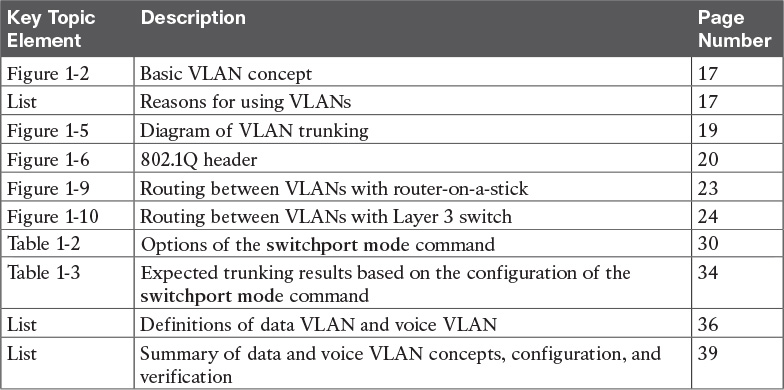
One key to doing well on the exams is to perform repetitive spaced review sessions. Review this chapter’s material using either the tools in the book, DVD, or interactive tools for the same material found on the book’s companion website. Refer to the “Your Study Plan” element for more details. Table 1-4 outlines the key review elements and where you can find them. To better track your study progress, record when you completed these activities in the second column.

Review All the Key Topics
Command References
Tables 1-6 and 1-7 list configuration and verification commands used in this chapter, respectively. As an easy review exercise, cover the left column in a table, read the right column, and try to recall the command without looking. Then repeat the exercise, covering the right column, and try to recall what the command does.

Table 1-6 Chapter 1 Configuration Command Reference

Table 1-7 Chapter 1 EXEC Command Reference