
The following objectives for Exam CX-310-200 are covered in this chapter:
Explain disk architecture including the UFS file system capabilities and naming conventions for devices for SPARC, x64, and x86-based systems.
![]() Device drivers control every device connected to your system, and some devices use multiple device drivers. This chapter explains device drivers so that you can recognize and verify all devices connected to your system. In addition, the Solaris operating system accesses devices, such as disks and tape drives, through device and path names. The system administrator must be familiar with the various path names that point to each piece of hardware connected to the system.
Device drivers control every device connected to your system, and some devices use multiple device drivers. This chapter explains device drivers so that you can recognize and verify all devices connected to your system. In addition, the Solaris operating system accesses devices, such as disks and tape drives, through device and path names. The system administrator must be familiar with the various path names that point to each piece of hardware connected to the system.
Explain when and how to list devices, reconfigure devices, perform disk partitioning, and relabel a disk in a Solaris operating environment using the appropriate files, commands, options, menus, and/or tables.
![]() The system administrator is responsible for adding and configuring new hardware on the system. This chapter describes how new devices are configured into the Solaris operating environment. You’ll need to describe disk architecture and understand naming conventions for disk devices as used in the Solaris operating environment.
The system administrator is responsible for adding and configuring new hardware on the system. This chapter describes how new devices are configured into the Solaris operating environment. You’ll need to describe disk architecture and understand naming conventions for disk devices as used in the Solaris operating environment.
![]() You’ll need to know how to set up the disks and disk partitions when installing the Solaris operating environment. However, to properly set up a disk, you first need to understand the concepts behind disk storage and partitioning. You then need to determine how you want data stored on your system’s disks.
You’ll need to know how to set up the disks and disk partitions when installing the Solaris operating environment. However, to properly set up a disk, you first need to understand the concepts behind disk storage and partitioning. You then need to determine how you want data stored on your system’s disks.
Explain the Solaris 10 OS file system, including disk-based, distributed, devfs, and memory file systems related to SMF, and create a new UFS file system using options for <1Tbyte and> 1Tbyte file systems.
![]() You’ll need to understand all of the file systems that are available in the Solaris operating environment. In addition, you’ll need to know when to use each type of file system.
You’ll need to understand all of the file systems that are available in the Solaris operating environment. In addition, you’ll need to know when to use each type of file system.
Explain when and how to create a new UFS using the newfs command, check the file system using fsck, resolve file system inconsistencies, and monitor file system usage using associated commands.
![]() You’ll need to be familiar with all of the commands used to create, check, and repair file systems. The system administrator needs to know how to use these tools and understand the effect that the various command options will have on performance and functionality.
You’ll need to be familiar with all of the commands used to create, check, and repair file systems. The system administrator needs to know how to use these tools and understand the effect that the various command options will have on performance and functionality.
Describe the purpose, features, and functions of root subdirectories, file components, file types, and hard links in the Solaris directory hierarchy.
Explain how to create and remove hard links in a Solaris directory.
![]() You’ll need to know how to create, remove, and identify a hard link and understand why they are used in the Solaris operating environment. You’ll need to be able to identify and describe all of the file types available in the Solaris operating environment. You’ll need to understand the purpose of each subdirectory located in the root file system and the type of information that is stored in these subdirectories.
You’ll need to know how to create, remove, and identify a hard link and understand why they are used in the Solaris operating environment. You’ll need to be able to identify and describe all of the file types available in the Solaris operating environment. You’ll need to understand the purpose of each subdirectory located in the root file system and the type of information that is stored in these subdirectories.
Explain the purpose and function of the vfstab file in mounting UFS file systems, and the function of the mnttab file system in tracking current mounts.
![]() You’ll need to maintain the table of file system defaults as you configure file systems to mount automatically at bootup. You’ll also need to understand the function of the mounted file system table (mnttab) and the entries made in this file.
You’ll need to maintain the table of file system defaults as you configure file systems to mount automatically at bootup. You’ll also need to understand the function of the mounted file system table (mnttab) and the entries made in this file.
Explain how to perform mounts and unmounts, and either access or restrict access to mounted diskettes and CD-ROMs.
![]() Each file system type supports options that control how the file system will function and perform. You’ll need to understand all of these custom file system parameters. The system administrator needs to be familiar with mounting and unmounting file systems and all of the options associated with the process.
Each file system type supports options that control how the file system will function and perform. You’ll need to understand all of these custom file system parameters. The system administrator needs to be familiar with mounting and unmounting file systems and all of the options associated with the process.
The following study strategies will help you prepare for the exam:
![]() This chapter introduces many new terms that you must know well enough to match to a description if they were to appear on the exam. Know the terms I’ve provided in the “Key Terms” section at the end of this chapter.
This chapter introduces many new terms that you must know well enough to match to a description if they were to appear on the exam. Know the terms I’ve provided in the “Key Terms” section at the end of this chapter.
![]() Understand what a device driver is and the various device driver names. They are rather difficult to remember, but keep going over them until you can describe them from memory. Many questions on the exam refer to the various types of device names.
Understand what a device driver is and the various device driver names. They are rather difficult to remember, but keep going over them until you can describe them from memory. Many questions on the exam refer to the various types of device names.
![]() Practice all the commands and step by steps until you can describe and perform them from memory. The best way to memorize them is to practice them repeatedly on a Solaris system.
Practice all the commands and step by steps until you can describe and perform them from memory. The best way to memorize them is to practice them repeatedly on a Solaris system.
![]() As with every chapter of this book, you’ll need a Solaris 10 system on which to practice. Practice every step-by-step example that is presented until you can perform the steps from memory. Also, as you practice creating file systems, you’ll need some unused disk space with which to practice. I recommend an empty, secondary disk drive for this purpose.
As with every chapter of this book, you’ll need a Solaris 10 system on which to practice. Practice every step-by-step example that is presented until you can perform the steps from memory. Also, as you practice creating file systems, you’ll need some unused disk space with which to practice. I recommend an empty, secondary disk drive for this purpose.
![]() Familiarize yourself with the various types of file systems described in this chapter, but specifically, pay close attention to the UFS type and UFS parameters. Most questions on the exam revolve around the UFS. In addition, make sure you understand the Solaris Volume Manager. You don’t need to know how to use it—just understand what it does and why you would use it.
Familiarize yourself with the various types of file systems described in this chapter, but specifically, pay close attention to the UFS type and UFS parameters. Most questions on the exam revolve around the UFS. In addition, make sure you understand the Solaris Volume Manager. You don’t need to know how to use it—just understand what it does and why you would use it.
![]() Make sure that you practice disk slicing. Understand how to create and delete disk slices and pay close attention to the limitations inherent with standard disk slices. Practice partitioning a disk using the
Make sure that you practice disk slicing. Understand how to create and delete disk slices and pay close attention to the limitations inherent with standard disk slices. Practice partitioning a disk using the format utility and SMC GUI tools until you have the process memorized.
![]() Finally, understand how to mount and unmount a file system as well as how to configure the /etc/vfstab file. Make sure that you understand all of the commands described in this chapter that are used to manage and display information about file systems, such as
Finally, understand how to mount and unmount a file system as well as how to configure the /etc/vfstab file. Make sure that you understand all of the commands described in this chapter that are used to manage and display information about file systems, such as df, fsck, and prtvtoc.
Before we can describe file systems, it’s important that you understand how Solaris views the disk drives and various other hardware components on your system. In particular, you need to understand how these devices are configured and named before you can create a file system on them or install the Solaris operating environment.
Device management in the Solaris 10 environment includes adding and removing peripheral devices from a system, such as tape drives, disk drives, printers, and modems. Device management also involves adding a third-party device driver to support a device if the device driver is not available in Sun’s distribution of the Solaris operating environment. System administrators need to know how to specify device names if using commands to manage disks, file systems, and other devices.
This chapter describes disk device management in detail. It also describes disk device naming conventions as well as adding, configuring, and displaying information about disk devices attached to your system.
Objective:
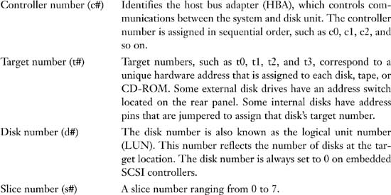
Describe the basic architecture of a local disk and the naming conventions for disk devices as used in the Solaris operating environment.
Explain when and how to list and reconfigure devices.
A computer typically uses a wide range of peripheral and mass-storage devices such as a small computer system interface (SCSI) disk drive, a keyboard, a mouse, and some kind of magnetic backup medium. Other commonly used devices include CD-ROM drives, printers, and various Universal Serial Bus (USB) devices. Solaris communicates with peripheral devices through device files or drivers. A device driver is a low-level program that allows the kernel to communicate with a specific piece of hardware. The driver serves as the operating system’s “interpreter” for that piece of hardware. Before Solaris can communicate with a device, the device must have a device driver.
When a system is started for the first time, the kernel creates a device hierarchy to represent all the devices connected to the system. This is the autoconfiguration process, which is described later in this chapter. If a driver is not loaded for a particular peripheral, that device is not functional. In Solaris, each disk device is described in three ways, using three distinct naming conventions:
![]() Physical device name—Represents the full device pathname in the device information hierarchy.
Physical device name—Represents the full device pathname in the device information hierarchy.
![]() Instance name—Represents the kernel’s abbreviation name for every possible device on the system.
Instance name—Represents the kernel’s abbreviation name for every possible device on the system.
![]() Logical device name—Used by system administrators with most file system commands to refer to devices.
Logical device name—Used by system administrators with most file system commands to refer to devices.
System administrators need to understand these device names when using commands to manage disks and file systems. We discuss these device names throughout this chapter.
Exam Alert
Memorize these device names. You’ll encounter them in several questions and it’s important that you understand when and where each name is used. Make sure you can identify a particular device driver name when it is presented as a filename.
Before the operating system is loaded, the system locates a particular device through the device tree, also called the full device pathname. Full device pathnames are described in Chapter 3, “Perform System Boot and Shutdown Procedures.” After the kernel is loaded, however, a device is located by its physical device pathname. Physical device names represent the full device pathname for a device. Note that the two names have the same structure. For example, the full device pathname for a SCSI disk at target 0 on a Sun Ultra 450 system is as follows:
/pci@1f,4000/scsi@3/disk@0,0
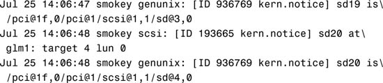
Now let’s look at the corresponding physical device name from the operating system level. Use the dmesg command, described later in this section, to obtain information about devices connected to your system. By typing dmesg at the command prompt, you’ll receive the following information about SCSI disks 3 and 4:
This same information is also available in the /var/adm/messages file.
The physical device pathnames for disks 3 and 4 are as follows:

As you can see, the physical device name and the full device name are the same. The difference is that the full device pathname is simply a path to a particular device. The physical device is the actual driver used by Solaris to access that device from the operating system.
Physical device files are found in the /devices directory. The content of the /devices directory is controlled by the devfs file system. The entries in the /devices directory dynamically represent the current state of accessible devices in the kernel and require no administration. New device entries are added when the devices are detected and added to the kernel. The physical device files for SCSI disks 3 and 4 would be
/devices/pci@1f,0/pci@1/scsi@1,1/sd@3,0:<#>
/devices/pci@1f,0/pci@1/scsi@1,1/sd@4,0:<#>
for the block device and
/devices/pci@1f,0/pci@1/scsi@1,1/sd@3,0:<#>,raw
/devices/pci@1f,0/pci@1/scsi@1,1/sd@4,0:<#>,raw
for the character (raw) device, where <#> is a letter representing the disk slice. Block and character devices are described later in this chapter in the section titled “Block and Raw Devices.”
The system commands used to provide information about physical devices are described in Table 1.1.

Note
prtconf Output The output produced by the prtconf command can vary depending on the version of the system’s PROM.
prtconf
The following output is displayed:


Use the -v option to display detailed information about devices such as information about the attached SCSI disks:
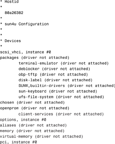
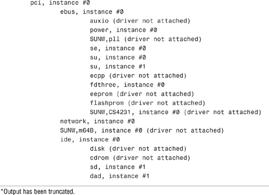
Next is an example of the output displayed by the sysdef command. Type the sysdef command:
sysdef
The following output is displayed:
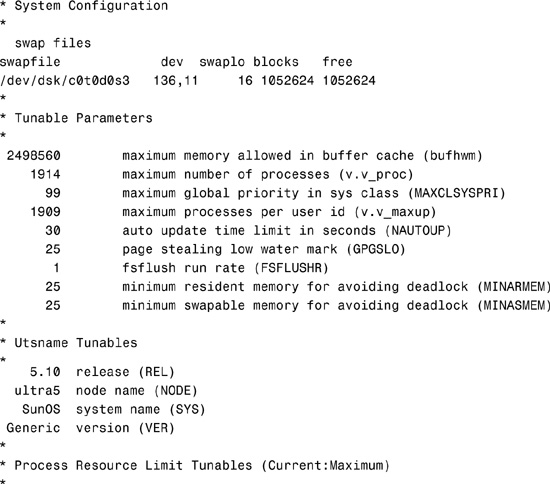
0x0000000000000100:0x0000000000010000 file descriptors
*
* Streams Tunables
*
9 maximum number of pushes allowed (NSTRPUSH)
65536 maximum stream message size (STRMSGSZ)
1024 max size of ctl part of message (STRCTLSZ)
*
* IPC Messages module is not loaded
*
*
* IPC Semaphores module is not loaded
*
*
* IPC Shared Memory module is not loaded
*
*
* Time Sharing Scheduler Tunables
*
60 maximum time sharing user priority (TSMAXUPRI)
SYS system class name (SYS_NAME)
*Output has been truncated.
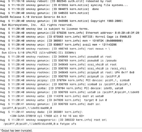
Finally, here’s an example of the device information for an Ultra system displayed using the dmesg command:
dmesg
The following output is displayed:
Use the output of the prtconf command to identify which disk, tape, and CD-ROM devices are connected to the system. As shown in the preceding prtconf and sysdef example, some devices display the driver not attached message next to the device instance. This message does not always mean that a driver is unavailable for this device. It means that no driver is currently attached to the device instance because there is no device at this node or the device is not in use. The operating system automatically loads drivers when the device is accessed, and it unloads them when it is not in use.
The system determines what devices are attached to it at startup. This is why it is important to have all peripherals powered on at startup, even if they are not currently being used. During startup, the kernel configures itself dynamically, loading needed modules into memory. Device drivers are loaded when devices, such as disk and tape devices, are accessed for the first time. This process is called autoconfiguration because all kernel modules are loaded automatically if needed. As described in Chapter 3, the system administrator can customize the way in which kernel modules are loaded by modifying the /etc/system file.
Autoconfiguration offers many advantages over the manual configuration method used in earlier versions of Unix, in which device drivers were manually added to the kernel, the kernel was recompiled, and the system had to be restarted. Now, with autoconfiguration, the administrator simply connects the new device to the system and performs a reconfiguration startup. To perform a reconfiguration startup, follow the steps in Step by Step 1.1.
STEP BY STEP
1.1 Performing a Reconfiguration Startup
1. Create the /reconfigure file with the following command:
touch /reconfigure
The /reconfigure file causes the Solaris software to check for the presence of any newly installed devices the next time you turn on or start up your system.
2. Shut down the system using the shutdown procedure described in Chapter 3.
If you need to connect the device, turn off power to the system and all peripherals after Solaris has been properly shut down.
After the new device is connected, restore power to the peripherals first and then to the system. Verify that the peripheral device has been added by attempting to access it.
Note
Automatic Removal of /reconfigure The file named /reconfigure automatically gets removed during the bootup process.
An optional method of performing a reconfiguration startup is to type boot -r at the OpenBoot prompt.
Note
Specify a Reconfiguration Reboot As root, you can also issue the reboot -- -r command from the Unix shell. The -- -r passes the -r to the boot command.
During a reconfiguration restart, a device hierarchy is created in the /devices file system to represent the devices connected to the system. The kernel uses this to associate drivers with their appropriate devices.
Autoconfiguration offers the following benefits:
![]() Main memory is used more efficiently because modules are loaded as needed.
Main memory is used more efficiently because modules are loaded as needed.
![]() There is no need to reconfigure the kernel if new devices are added to the system. When you add devices such as disks or tape drives other than USB and hot-pluggable devices, the system needs to be shut down before you connect the hardware so that no damage is done to the electrical components.
There is no need to reconfigure the kernel if new devices are added to the system. When you add devices such as disks or tape drives other than USB and hot-pluggable devices, the system needs to be shut down before you connect the hardware so that no damage is done to the electrical components.
![]() Drivers can be loaded and tested without having to rebuild the kernel and restart the system.
Drivers can be loaded and tested without having to rebuild the kernel and restart the system.
Note
devfsadm Another option used to automatically configure devices on systems that must remain running 24×7, and one that does not require a reboot, is the devfsadm command.
Occasionally, you might install a new device for which Solaris does not have a supporting device driver. Always check with the manufacturer to make sure any device you plan to add to your system has a supported device driver. If a driver is not included with the standard Solaris release, the manufacturer should provide the software needed for the device to be properly installed, maintained, and administered.
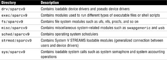
Third-party device drivers are installed as software packages using the pkgadd command. At a minimum, this software includes a device driver and its associated configuration (.conf) file. The .conf file resides in the /kernel/drv directory. Table 1.2 describes the contents of the module subdirectories located in the /kernel directory.
Universal Serial Bus (USB) devices were developed to provide a method to attach peripheral devices such as keyboards, printers, cameras, and disk drives using a common connector and interface. Furthermore, USB devices are hot-pluggable, which means they can be connected or disconnected while the system is running. The operating system automatically detects when a USB device has been connected and automatically configures the operating environment to make it available.
The Solaris 10 operating environment supports USB devices on Sun Blade, Netra, Sunfire, and x86/x64-based system. In addition, a USB interface can be added to Sun systems that may not already have one.
When hot-plugging a USB device, the device is immediately displayed in the device hierarchy. For example, a full device pathname for a USB Zip drive connected to an Ultra system would appear as follows:
/pci@1f,4000/usb@5/storage@1
A printer would look like this:
/pci@1f,4000/usb@5/hub@3/printer@1
Be careful when removing USB devices, however. If the device is being used when it is disconnected, you will get I/O errors and possible data errors. When this happens, you’ll need to plug the device back in, stop the application that is using the device, and then unplug the device.
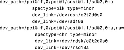
As stated in the “Volume Management” section later in this chapter, removable media such as floppy diskettes and CD-ROMs can be inserted and automatically mounted. When attaching a hot-pluggable device, it’s best to restart vold after attaching the USB device as follows: pkill -HUP vold
Once vold identifies that the device has been connected, you’ll see device names set up as follows:
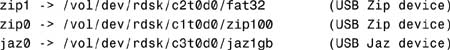
When disconnecting a USB device such as a Zip drive, unmount the device, stop vold, disconnect the device, and then restart vold as follows:
1. Stop any application that is using the device.
2. Unmount the USB device using the volrmmount command as follows:
volrmmount -e zip0
or the eject command as follows:
eject zip0
zip0 is a nickname for the Zip device. The following nicknames are recognized:
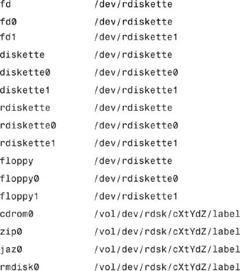
The -e option simulates the ejection of the media. For a more up-to-date listing of nicknames that might have been added since this writing, consult the volrmmount man page.
3. As root, stop vold:
/etc/init.d/volmgt stop
4. Disconnect the USB device.
5. Start vold:
/etc/init.d/volmgt start
For more information on vold and USB devices, see the section titled “Volume Management” later in this chapter.
The instance name represents the kernel’s abbreviated name for every possible device on the system. For example, on an Ultra system, dad0 represents the instance name of the IDE disk drive, sd0 represents a SCSI disk, and hme0 is the instance name for the network interface. Instance names are mapped to a physical device name in the /etc/path_to_inst file. The following shows the contents of a path_to_inst file:
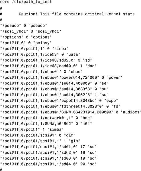
Although instance names can be displayed using the commands dmesg, sysdef, and prtconf, the only command that shows the mapping of the instance name to the physical device name is the dmesg command. For example, you can determine the mapping of an instance name to a physical device name by looking at the dmesg output, as shown in the following example from an Ultra system:
sd19 is /pci@1f,0/pci@1/scsi@1,1/sd@3,0
dad1 is /pci@1f,0/pci@1,1/ide@3/dad@0,0
In the first example, sd19 is the instance name and /pci@1f,0/pci@1/scsi@1,1/sd@3,0 is the physical device name. In the second example, dad1 is the instance name and /pci@1f,0/pci@1,1/ide@3/dad@0,0 is the physical device name. After the instance name has been assigned to a device, it remains mapped to that device. To keep instance numbers consistent across restarts, the system records them in the /etc/path_to_inst file. This file is only read at startup, and it is updated by the devfsadmd daemon described later in this section.
Devices already existing on a system are not rearranged when new devices are added, even if new devices are added to pci slots that are numerically lower than those occupied by existing devices. In other words, the /etc/path_to_inst file is appended to, not rewritten, when new devices are added.
It is generally not necessary for the system administrator to change the path_to_inst file because the system maintains it. The system administrator can, however, change the assignment of instance numbers by editing this file and doing a reconfiguration startup. However, any changes made in this file are lost if the devfsadm command is run before the system is restarted.
Note
Resolving Problems with /etc/path_to_inst If you can’t start up from the startup disk because of a problem with the /etc/path_to_inst file, you should start up from the CD-ROM (boot cdrom -s) and remove the /etc/path_to_inst file from the startup disk. To do this, start up from the CD-ROM using boot cdrom -s at the OpenBoot prompt. Use the rm command to remove the file named /a/etc/path_to_inst. The path_to_inst file will automatically be created the next time the system boots.
You can add new devices to a system without requiring a reboot. It’s all handled by the devfsadmd daemon that transparently builds the necessary configuration entries for those devices capable of notifying the kernel when the device is added (such as USB, FC-AL, disks, and so on). Before Solaris 7, you needed to run several devfs administration tools such as drvconfig, disks, tapes, ports, and devlinks to add in the new device and create the /dev and /devices entries necessary for the Solaris operating environment to access the new device. These tools are still available but only for compatibility purposes; drvconfig and the other link generators are symbolic links to the devfsadm utility. Furthermore, these older commands are not aware of hot-pluggable devices, nor are they flexible enough for devices with multiple instances. The devfsadm command should now be used in place of all these commands; however, devfsadmd, the devfsadm daemon, automatically detects device configuration changes, so there should be no need to run this command interactively unless the device is unable to notify the kernel that it has been added to the system.
An example of when to use the devfsadm command would be if the system had been started but the power to the CD-ROM or tape drive was not turned on. During startup, the system did not detect the device; therefore, its drivers were not installed. This can be verified by issuing the sysdef command and examining the output for sd6, the SCSI target ID normally used for the external CD-ROM:
sd, instance #6 (driver not attached)
To gain access to the CD-ROM, you could halt the system, turn on power to the CD-ROM, and start the system backup, or you could simply turn on power to the CD-ROM and issue the following command at the command prompt:
devfsadm
When used without any options, devfsadm will attempt to load every driver in the system and attach each driver to its respective device instances. You can restrict devfsadm to only look at specific devices using the -c option as follows:
devfsadm -c disk -c tape
This restricts the devfsadm command to devices of class disk and tape. As shown, the -c option can be used more than once to specify more than one device class.
Now, if you issue the sysdef command, you’ll see the following output for the CD-ROM:
sd, instance #6
You can also use the devfsadm command to configure only the devices for a specific driver such as “st” by using the -i option as follows:
devfsadm -i st
The devfsadm command will only configure the devices for the driver named “st.”
Each device has a major and minor device number assigned to it. These numbers identify the proper device location and device driver to the kernel. This number is used by the operating system to key into the proper device driver whenever a physical device file corresponding to one of the devices it manages is opened. The major device number maps to a device driver such as sd, st, or hme. The minor device number indicates the specific member within that class of devices. All devices managed by a given device driver contain a unique minor number. Some drivers of pseudo devices (software entities set up to look like devices) create new minor devices on demand. Together, the major and minor numbers uniquely define a device and its device driver.
Physical device files have a unique output when listed with the ls -l command, as shown in the following example:
The system responds with this:
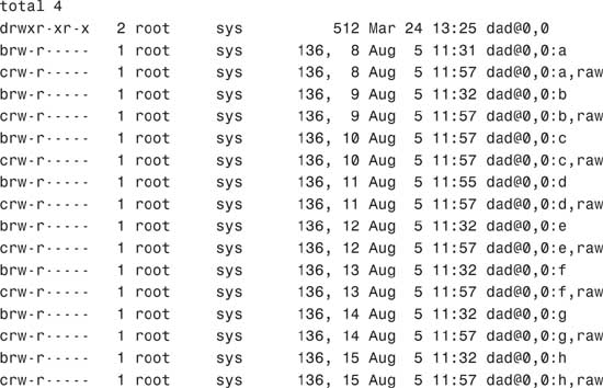
This long listing includes columns showing major and minor numbers for each device. The dad driver manages all the devices listed in the previous example, which have a major number of 136. Minor numbers are listed after the comma.
During the process of building the /devices directory, major numbers are assigned based on the kernel module attached to the device. Each device is assigned a major device number by using the name-to-number mappings held in the /etc/name_to_major file. This file is maintained by the system and is undocumented. The following is a sample of the /etc/name_to_major file:
more /etc/name_to_major
cn 0
rootnex 1
pseudo 2
ip 3
logindmux 4
icmp 5
fas 6
hme 7
p9000 8
p9100 9
sp 10
clone 11
sad 12
mm 13
iwscn 14
wc 15
conskbd 16
consms 17
ipdcm 18
dump 19
se 20
log 21
sy 22
ptm 23
pts 24
ptc 25
ptsl 26
bwtwo 27
audio 28
zs 29
cgthree 30
cgtwo 31
sd 32
st 33
...
...
envctrl 131
cvc 132
cvcredir 133
eide 134
hd 135
tadbat 136
ts102 137
simba 138
uata 139
dad 140
atapicd 141
To create the minor device entries, the devfsadmd daemon uses the information placed in the dev_info node by the device driver. Permissions and ownership information are kept in the /etc/minor_perm file.
The final stage of the autoconfiguration process involves the creation of the logical device name to reflect the new set of devices on the system. To see a list of logical device names for the disks connected to a SPARC system, execute a long listing on the /dev/dsk directory, as follows:
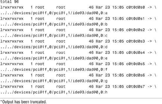
On the second line of output from the ls -l command, notice that the logical device name c0t0d0s0 is linked to the physical device name, as shown in the following:
../../devices/pci@1f,0/pci@1,1/ide@3/dad@0,0:a
On Sun SPARC systems, you’ll see an eight string logical device name for each disk slice that contains the controller number, the target number, the disk number, and the slice number (c#t#d#s#).
X86-based Solaris systems have a different disk naming convention, but before describing the logical device name for a disk on an x86-based system, it’s worth pointing out a fundamental difference between disk slicing on a SPARC system and disk slicing on an x86-based system. Disk partitioning on the Solaris for the x86 platform has one more level than that of Solaris for SPARC. On Solaris for SPARC, slices and partitions are one and the same; on Solaris for x86, slices are “subpartitions” of a PC partition. This was done to allow Solaris to coexist with other PC operating systems, such as for dual boot configurations.
This difference in slicing brings some differences in the naming of disk devices on a Solaris x86-based PC. Slices are created in the first Solaris partition on a drive and, for SCSI disks, are named the same as on the Solaris for SPARC (c#t#d0s#). However, because slices are within a PC partition, the PC partitions have their own device names. The entire drive is named c#t#d0p0, and the PC partitions (maximum of 4) are c#t#d0p1 through c#t#d0p4. To support the x86 environment, the format utility also has an added command called fdisk to deal with the PC partitions.
Solaris x86-based systems have 16 slices versus 8 for SPARC. On the x86 PC, slice 8 is used to hold boot code and slice 9 is used for alternate sectors on some types of disks. Higher slices are available for use, but not supported by format at this time.
The major differences between the logical device names used on SPARC-based systems versus x86-based systems are as follows:
![]() c is the controller number.
c is the controller number.
![]() t is the SCSI target number.
t is the SCSI target number.
![]() s is the slice number.
s is the slice number.
![]() p represents the
p represents the fdisk partition (not slice partition).
![]() d is the LUN number or IDE Drive Number.
d is the LUN number or IDE Drive Number.
If an IDE drive is used, d is used to determine MASTER or SLAVE and the t is not used for IDE drives. For example, two controllers are installed on an x86 PC:
![]() c0 is an IDE controller.
c0 is an IDE controller.
![]() c1 is a SCSI controller.
c1 is a SCSI controller.
On an x86-based Solaris system, the following devices are listed in the /dev/dsk directory:

It’s easy to see which devices are IDE disks because they do not have a “t” in the logical device name, while the SCSI disks with “c1” have a target number listed. This system has one IDE drive and five SCSI drives listed, targets 0, 1, 2, 5, and 6 (t6 is typically the CD-ROM).
Note
In this text and in the examples, unless otherwise noted, I will be using SPARC-based logical device names.
On both SPARC-based and x86-based systems, the logical device name is the name that the system administrator uses to refer to a particular device when running various Solaris file system commands. For example, if running the mount command, use the logical device name /dev/dsk/c0t0d0s7 to mount the file system /home:
mount /dev/dsk/c0t0d0s7 /home
Logical device files in the /dev directory are symbolically linked to physical device files in the /devices directory. Logical device names are used to access disk devices if you do any of the following:
![]() Add a new disk to the system.
Add a new disk to the system.
![]() Move a disk from one system to another.
Move a disk from one system to another.
![]() Access (or mount) a file system residing on a local disk.
Access (or mount) a file system residing on a local disk.
![]() Back up a local file system.
Back up a local file system.
![]() Repair a file system.
Repair a file system.
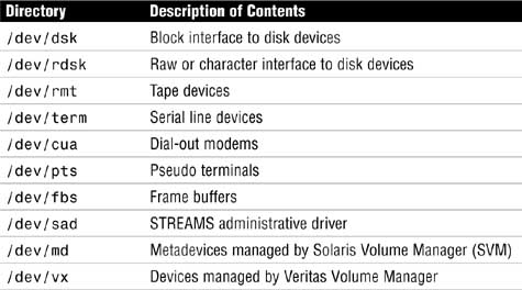
Logical devices are organized in subdirectories under the /dev directory by their device types, as shown in Table 1.3.
Disk drives have an entry under both the /dev/dsk and /dev/rdsk directories. The /dsk directory refers to the block or buffered device file, and the /rdsk directory refers to the character or raw device file. The “r” in rdsk stands for “raw.” You may even hear these devices referred to as “cooked” and “uncooked” devices. If you are not familiar with these devices, refer to Chapter 2, “Installing the Solaris 10 Operating Environment,” where block and character devices are described.
The /dev/dsk directory contains the disk entries for the block device nodes in /devices, as shown in the following command output:

The /dev/rdsk directory contains the disk entries for the character device nodes in /devices, as shown in the following command:
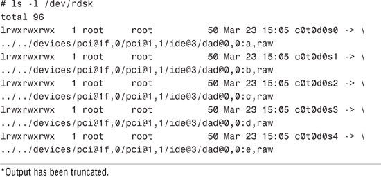
*Output has been truncated.
You should now have an understanding of how Solaris identifies disk drives connected to the system. The remainder of this chapter describes how to create file systems on these devices. It will also describe how to manage file systems and monitor disk space usage, some of the fundamental concepts you’ll need for the first exam.
Exam Alert
Make sure you understand when to use a raw device and when to use a buffered device. You’ll encounter several questions on the exam where you will need to select either the raw or buffered device for a particular command.
A file system is a collection of files and directories stored on disk in a standard Unix file system (UFS) format. All disk-based computer systems have a file system. In Unix, file systems have two basic components: files and directories. A file is the actual information as it is stored on the disk, and a directory is a list of the filenames. In addition to keeping track of filenames, the file system must keep track of files’ access dates, permissions, and ownership. Managing file systems is one of the system administrator’s most important tasks. Administration of the file system involves the following:
![]() Ensuring that users have access to data. This means that systems are up and operational, file permissions are set up properly, and data is accessible.
Ensuring that users have access to data. This means that systems are up and operational, file permissions are set up properly, and data is accessible.
![]() Protecting file systems against file corruption and hardware failures. This is accomplished by checking the file system regularly and maintaining proper system backups.
Protecting file systems against file corruption and hardware failures. This is accomplished by checking the file system regularly and maintaining proper system backups.
![]() Securing file systems against unauthorized access. Only authorized users should have access to files.
Securing file systems against unauthorized access. Only authorized users should have access to files.
![]() Providing users with adequate space for their files.
Providing users with adequate space for their files.
![]() Keeping the file system clean. In other words, data in the file system must be relevant and not wasteful of disk space. Procedures are needed to make sure that users follow proper naming conventions and that data is stored in an organized manner.
Keeping the file system clean. In other words, data in the file system must be relevant and not wasteful of disk space. Procedures are needed to make sure that users follow proper naming conventions and that data is stored in an organized manner.
You’ll see the term file system used in several ways. Usually, file system describes a particular type of file system (disk-based, network based, or virtual). It might also describe the entire file tree from the root directory downward. In another context, the term file system might be used to describe the structure of a disk slice, described later in this chapter.
The Solaris system software uses the virtual file system (VFS) architecture, which provides a standard interface for different file system types. The VFS architecture lets the kernel handle basic operations, such as reading, writing, and listing files, without requiring the user or program to know about the underlying file system type. Furthermore, Solaris provides file system administrative commands that enable you to maintain file systems.
Before creating a file system on a disk, you need to understand the basic geometry of a disk drive. Disks come in many shapes and sizes. The number of heads, tracks, and sectors and the disk capacity vary from one model to another. Basic disk terminology is described in Table 1.4.
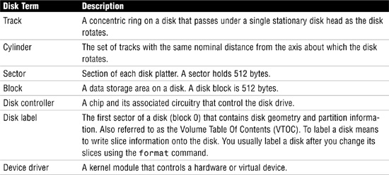
A hard disk consists of several separate disk platters mounted on a common spindle. Data stored on each platter surface is written and read by disk heads. The circular path that a disk head traces over a spinning disk platter is called a track.
Each track is made up of a number of sectors laid end to end. A sector consists of a header, a trailer, and 512 bytes of data. The header and trailer contain error-checking information to help ensure the accuracy of the data. Taken together, the set of tracks traced across all the individual disk platter surfaces for a single position of the heads is called a cylinder.
Associated with every disk is a controller, an intelligent device responsible for organizing data on the disk. Some disk controllers are located on a separate circuit board, such as SCSI. Other controller types are integrated with the disk drive, such as Integrated Device Electronics (IDE) and Enhanced IDE (EIDE).
Disks might contain areas where data cannot be written and retrieved reliably. These areas are called defects. The controller uses the error-checking information in each disk block’s trailer to determine whether a defect is present in that block. When a block is found to be defective, the controller can be instructed to add it to a defect list and avoid using that block in the future. The last two cylinders of a disk are set aside for diagnostic use and for storing the disk defect list.
A special area of every disk is set aside for storing information about the disk’s controller, geometry, and slices. This information is called the disk’s label or volume table of contents (VTOC).
To label a disk means to write slice information onto the disk. You usually label a disk after defining its slices. If you fail to label a disk after creating slices, the slices will be unavailable because the operating system has no way of knowing about them.
Solaris supports two types of disk labels, the VTOC disk label and the EFI disk label. Solaris 10 (and later versions of Solaris 9) provides support for disks that are larger than 1 terabyte on systems that run a 64-bit Solaris kernel. The acronym EFI stands for Extensible Firmware Interface and this new label format is REQUIRED for all devices over 1TB in size, and cannot be converted back to VTOC.
The EFI label provides support for physical disks and virtual disk volumes. Solaris 10 also includes updated disk utilities for managing disks greater than 1 terabyte. The UFS file system is compatible with the EFI disk label, and you can create a UFS file system greater than 1 terabyte.
The traditional VTOC label is still available for disks less than 1 terabyte in size. If you are only using disks smaller than 1 terabyte on your systems, managing disks will be the same as in previous Solaris releases. In addition, you can use the format-e command to label a disk less than 1TB with an EFI label.
The advantages of the EFI disk label over the VTOC disk label are as follows:
![]() Provides support for disks greater than 1 terabyte in size.
Provides support for disks greater than 1 terabyte in size.
![]() Provides usable slices 0–6, where slice 2 is just another slice.
Provides usable slices 0–6, where slice 2 is just another slice.
![]() Partitions (or slices) cannot overlap with the primary or backup label, nor with any other partitions. The size of the EFI label is usually 34 sectors, so partitions start at sector 34. This feature means that no partition can start at sector zero (0).
Partitions (or slices) cannot overlap with the primary or backup label, nor with any other partitions. The size of the EFI label is usually 34 sectors, so partitions start at sector 34. This feature means that no partition can start at sector zero (0).
![]() No cylinder, head, or sector information is stored in the EFI label. Sizes are reported in blocks.
No cylinder, head, or sector information is stored in the EFI label. Sizes are reported in blocks.
![]() Information that was stored in the alternate cylinders area, the last two cylinders of the disk, is now stored in slice 8.
Information that was stored in the alternate cylinders area, the last two cylinders of the disk, is now stored in slice 8.
![]() If you use the
If you use the format utility to change partition sizes, the unassigned partition tag is assigned to partitions with sizes equal to zero. By default, the format utility assigns the usr partition tag to any partition with a size greater than zero. You can use the partition change menu to reassign partition tags after the partitions are changed.
![]() Solaris ZFS (zettabyte file system) uses EFI labels by default. As of this writing, ZFS file systems are not implemented but are expected in a future Solaris 10 update.
Solaris ZFS (zettabyte file system) uses EFI labels by default. As of this writing, ZFS file systems are not implemented but are expected in a future Solaris 10 update.
The following lists restrictions of the EFI disk label:
![]() The SCSI driver, ssd or sd, currently supports only up to 2 terabytes. If you need greater disk capacity than 2 terabytes, use a disk and storage management product such as Solaris Volume Manager to create a larger device.
The SCSI driver, ssd or sd, currently supports only up to 2 terabytes. If you need greater disk capacity than 2 terabytes, use a disk and storage management product such as Solaris Volume Manager to create a larger device.
![]() Layered software products intended for systems with EFI-labeled disks might be incapable of accessing a disk without an EFI disk label.
Layered software products intended for systems with EFI-labeled disks might be incapable of accessing a disk without an EFI disk label.
![]() You cannot use the
You cannot use the fdisk command on a disk with an EFI label that is greater than 1 terabyte in size.
![]() A disk with an EFI label is not recognized on systems running previous Solaris releases.
A disk with an EFI label is not recognized on systems running previous Solaris releases.
![]() The EFI disk label is not supported on IDE disks.
The EFI disk label is not supported on IDE disks.
![]() You cannot boot from a disk with an EFI disk label.
You cannot boot from a disk with an EFI disk label.
![]() You cannot use the Solaris Management Console’s Disk Manager tool to manage disks with EFI labels. Use the format utility to partition disks with EFI labels. Then, you can use the Solaris Management Console’s Enhanced Storage Tool to manage volumes and disk sets with EFI-labeled disks.
You cannot use the Solaris Management Console’s Disk Manager tool to manage disks with EFI labels. Use the format utility to partition disks with EFI labels. Then, you can use the Solaris Management Console’s Enhanced Storage Tool to manage volumes and disk sets with EFI-labeled disks.
![]() The EFI specification prohibits overlapping slices. The entire disk is represented by c#t#d#.
The EFI specification prohibits overlapping slices. The entire disk is represented by c#t#d#.
![]() The EFI disk label provides information about disk or partition sizes in sectors and blocks, but not in cylinders and heads.
The EFI disk label provides information about disk or partition sizes in sectors and blocks, but not in cylinders and heads.
![]() The following
The following format options are either not supported or are not applicable on disks with EFI labels:
![]() The
The save option is not supported because disks with EFI labels do not need an entry in the format.dat file.
![]() The
The backup option is not applicable because the disk driver finds the primary label and writes it back to the disk.
An important part of the disk label is the partition table, which identifies a disk’s slices, the slice boundaries (in cylinders), and the total size of the slices. A disk’s partition table can be displayed by using the format utility described in the “Disk Slices” section later in this chapter.
Objective:
Describe the purpose, features, and functions of disk-based, networked, and pseudo file systems in a Solaris operating environment, and explain the differences among these file system types.
Solaris file systems can be put into three categories: disk-based, network-based, and virtual.
Disk-based file systems reside on the system’s local disk. As of this writing, the following are four types of disk-based file systems found in Solaris 10:
![]() UFS (Unix File System)—The Unix file system, which is based on the BSD FFS Fast file system (the traditional Unix file system). The UFS is the default disk-based file system used in Solaris.
UFS (Unix File System)—The Unix file system, which is based on the BSD FFS Fast file system (the traditional Unix file system). The UFS is the default disk-based file system used in Solaris.
![]() HSFS (High Sierra File System)—The High Sierra and ISO 9660 file system, which supports the Rock Ridge extensions. The HSFS file system is used on CD-ROMs and is a read-only file system.
HSFS (High Sierra File System)—The High Sierra and ISO 9660 file system, which supports the Rock Ridge extensions. The HSFS file system is used on CD-ROMs and is a read-only file system.
![]() PCFS (PC File System)—The PC file system, which allows read/write access to data and programs on DOS-formatted disks written for DOS-based personal computers.
PCFS (PC File System)—The PC file system, which allows read/write access to data and programs on DOS-formatted disks written for DOS-based personal computers.
![]() UDF (Universal Disk Format)—The Universal Disk Format file system. UDF is the new industry-standard format for storing information on optical media technology called DVD (digital versatile disc).
UDF (Universal Disk Format)—The Universal Disk Format file system. UDF is the new industry-standard format for storing information on optical media technology called DVD (digital versatile disc).
![]() Not in Solaris 10 as of this writing, but worth noting is the zettabyte file system (ZFS), scheduled for a future Solaris 10 update, incorporating advanced data security and protection features, eliminating the need for
Not in Solaris 10 as of this writing, but worth noting is the zettabyte file system (ZFS), scheduled for a future Solaris 10 update, incorporating advanced data security and protection features, eliminating the need for fsck or other recovery mechanisms. By redefining file systems as virtualized storage, Solaris ZFS will enable virtually unlimited scalability.
Network-based file systems are file systems accessed over the network. Typically, they reside on one system and are accessed by other systems across the network.
The network file system (NFS) or remote file systems are file systems made available from remote systems. NFS is the only available network-based file system bundled with the Solaris operating environment. NFS is discussed in detail in Chapter 9, “Virtual File Systems, Swap Space, and Core Dumps.”
Virtual file systems, previously called pseudo file systems, are virtual or memory-based file systems that create duplicate paths to other disk-based file systems or provide access to special kernel information and facilities. Most virtual file systems do not use file system disk space, although a few exceptions exist. Cache file systems, for example, use a disk-based file system to contain the cache.
Some virtual file systems, such as the temporary file system, might use the swap space on a physical disk. The following is a list of some of the more common types of virtual file systems:
![]() SWAPFS (Swap File System)—A file system used by the kernel for swapping. Swap space is used as a virtual memory storage area when the system does not have enough physical memory to handle current processes.
SWAPFS (Swap File System)—A file system used by the kernel for swapping. Swap space is used as a virtual memory storage area when the system does not have enough physical memory to handle current processes.
![]() PROCFS (Process File System)—The Process File System resides in memory. It contains a list of active processes, by process number, in the
PROCFS (Process File System)—The Process File System resides in memory. It contains a list of active processes, by process number, in the /proc directory. Commands such as ps use information in the /proc directory. Debuggers and other development tools can also access the processes’ address space by using file system calls.
![]() LOFS (Loopback File System)—The Loopback File System lets you create a new virtual file system, which can provide access to existing files using alternate pathnames. Once the virtual file system is created, other file systems can be mounted within it, without affecting the original file system.
LOFS (Loopback File System)—The Loopback File System lets you create a new virtual file system, which can provide access to existing files using alternate pathnames. Once the virtual file system is created, other file systems can be mounted within it, without affecting the original file system.
![]() CacheFS (Cache File System)—The Cache File System lets you use disk drives on local workstations to store frequently used data from a remote file system or CD-ROM. The data stored on the local disk is the cache.
CacheFS (Cache File System)—The Cache File System lets you use disk drives on local workstations to store frequently used data from a remote file system or CD-ROM. The data stored on the local disk is the cache.
![]() TMPFS (Temporary File System)—The Temporary File System uses local memory for file system reads and writes. Because TMPFS uses physical memory and not the disk, access to files in a TMPFS is typically much faster than to files in a UFS. Files in the temporary file system are not permanent; they are deleted when the file system is unmounted and when the system is shut down or rebooted. TMPFS is the default file system type for the
TMPFS (Temporary File System)—The Temporary File System uses local memory for file system reads and writes. Because TMPFS uses physical memory and not the disk, access to files in a TMPFS is typically much faster than to files in a UFS. Files in the temporary file system are not permanent; they are deleted when the file system is unmounted and when the system is shut down or rebooted. TMPFS is the default file system type for the /tmp directory in the SunOS system software. You can copy or move files into or out of the /tmp directory just as you would in a UFS /tmp. When memory is insufficient to hold everything in the temporary file system, the TMPFS uses swap space as a temporary backing store, as long as adequate swap space is present.
![]() MNTFS—The MNTFS type maintains information about currently mounted file systems. MNTFS is described later in this chapter.
MNTFS—The MNTFS type maintains information about currently mounted file systems. MNTFS is described later in this chapter.
![]() CTFS (Contract File System)—The CTFS is associated with the
CTFS (Contract File System)—The CTFS is associated with the /system/contract directory and is the interface for creating, controlling, and observing contracts. The service management facility (SMF) uses process contracts (a type of contract) to track the processes which compose a service.
![]() DEVFS (Device file System)—The DEVFS is used to manage the namespace of all devices on the system. This file system is used for the
DEVFS (Device file System)—The DEVFS is used to manage the namespace of all devices on the system. This file system is used for the /devices directory. The devfs file system is new in Solaris 10 and increases system boot performance because only device entries that are needed to boot the system are attached. New device entries are added as the devices are accessed.
![]() FDFS (File Descriptor File System)—The FDFS provides explicit names for opening files by using file descriptors.
FDFS (File Descriptor File System)—The FDFS provides explicit names for opening files by using file descriptors.
![]() OBJFS (Object File System)—The OBJFS (object) file system describes the state of all modules currently loaded by the kernel. This file system is used by debuggers to access information about kernel symbols without having to access the kernel directly.
OBJFS (Object File System)—The OBJFS (object) file system describes the state of all modules currently loaded by the kernel. This file system is used by debuggers to access information about kernel symbols without having to access the kernel directly.
Objective:
Perform disk partitioning and relabel a disk in a Solaris operating environment using the appropriate files, commands, options, menus, and/or tables.
Disks are divided into regions called disk slices or disk partitions. A slice is composed of a single range of contiguous blocks. It is a physical subset of the disk (except for slice 2, which represents the entire disk). A Unix file system or the swap area is built within these disk slices. The boundaries of a disk slice are defined when a disk is partitioned using the Solaris format utility or the Solaris Management Console Disks Tool, and the slice information for a particular disk can be viewed by using the prtvtoc command. Each disk slice appears to the operating system (and to the system administrator) as though it were a separate disk drive.
Disk slicing differs between the SPARC and the x86 platforms. On the SPARC platform, the entire disk is devoted to the Solaris OS; the disk can be divided into 8 slices, numbered 0–7. On the x86 platform, the disk is divided into fdisk partitions using the fdisk command. The Solaris fdisk partition is divided into 10 slices, numbered 0–9.
Note
Slices Versus Partitions Solaris device names use the term slice (and the letter s in the device name) to refer to the slice number. Slices were called partitions in SunOS 4.x. This book attempts to use the term slice whenever possible; however, certain interfaces, such as the format and prtvtoc commands, refer to slices as partitions.
A physical disk consists of a stack of circular platters, as shown in Figure 1.1. Data is stored on these platters in a cylindrical pattern. Cylinders can be grouped and isolated from one another. A group of cylinders is referred to as a slice. A slice is defined with start and end points, defined from the center of the stack of platters, which is called the spindle.
Disk slices are defined by an offset and a size in cylinders. The offset is the distance from cylinder 0. To define a slice, the administrator provides a starting cylinder and an ending cylinder. A disk can have up to eight slices, named 0 to 7, but it is uncommon to use partition 2 as a file system. (See Chapter 2 for a discussion of disk-storage systems and sizing partitions.)
Note
Using Slice 2 As a Partition Sometimes a relational database uses an entire disk and requires one single raw partition. It’s convenient in this circumstance to use slice 2, as it represents the entire disk, but is not recommended because you would be using cylinder 0. You should start your database partition on cylinder 1 so that you don’t risk overwriting the disk’s VTOC. UFS file systems are smart enough not to touch the VTOC, but some databases have proven to be not so friendly.
When setting up slices, remember these rules:
![]() Each disk slice holds only one file system.
Each disk slice holds only one file system.
![]() No file system can span multiple slices.
No file system can span multiple slices.
![]() After a file system is created, its size cannot be increased or decreased without repartitioning and destroying the partition directly before or after it.
After a file system is created, its size cannot be increased or decreased without repartitioning and destroying the partition directly before or after it.
![]() Slices cannot span multiple disks; however, multiple swap slices on separate disks are allowed.
Slices cannot span multiple disks; however, multiple swap slices on separate disks are allowed.
When we discuss logical volumes later in this chapter, you’ll learn how to get around some of these limitations in file systems.
Also follow these guidelines when planning the layout of file systems:
![]() Distribute the workload as evenly as possible among different I/O systems and disk drives. Distribute
Distribute the workload as evenly as possible among different I/O systems and disk drives. Distribute /home and swap directories evenly across disks. A single disk has limitations on how quickly data can be transferred. By spreading this load across more than one disk, you can improve performance exponentially. This concept is described in Chapter 10, “Managing Storage Volumes,” where I describe striping using the Solaris Volume Manager.
![]() Keep projects or groups within their own file system. This enables you to keep better track of data for backups, recovery, and security reasons. Some disks might have better performance than others. For multiple projects, you could create multiple file systems and distribute the I/O workload by putting high-volume projects on separate physical disks.
Keep projects or groups within their own file system. This enables you to keep better track of data for backups, recovery, and security reasons. Some disks might have better performance than others. For multiple projects, you could create multiple file systems and distribute the I/O workload by putting high-volume projects on separate physical disks.
![]() Use the faster drives for file systems that need quick access and the slower drives for data that might not need to be retrieved as quickly. Some systems have drives that were installed as original hardware along with newer, better performing, drives that were added on some time later. Maybe you have a database dedicated to a high-volume project. This would be a perfect candidate to put on the newer, faster disk while a less accessed project could go on the slower disk drive.
Use the faster drives for file systems that need quick access and the slower drives for data that might not need to be retrieved as quickly. Some systems have drives that were installed as original hardware along with newer, better performing, drives that were added on some time later. Maybe you have a database dedicated to a high-volume project. This would be a perfect candidate to put on the newer, faster disk while a less accessed project could go on the slower disk drive.
![]() It is not important for most sites to be concerned about keeping similar types of user files in the same file system.
It is not important for most sites to be concerned about keeping similar types of user files in the same file system.
![]() Occasionally, you might have some users who consistently create small or large files. You might consider creating a separate file system with more inodes for users who consistently create small files. (See the section titled “The inode” later in this chapter for more information on inodes.)
Occasionally, you might have some users who consistently create small or large files. You might consider creating a separate file system with more inodes for users who consistently create small files. (See the section titled “The inode” later in this chapter for more information on inodes.)
We discuss disk slices again in Chapter 2, where we describe setting up disk storage and planning the layout of your disk slices.
As described earlier, disk configuration information is stored in the disk label. If you know the disk and slice number, you can display information for a disk by using the print volume table of contents (prtvtoc) command. You can specify the volume by specifying any slice defined on the disk (for example, /dev/rdsk/c0t3d0s2 or /dev/rdsk/c0t3d0s*). Regardless of which slice you specify, all slices defined on the disk will be displayed. If you know the target number of the disk but do not know how it is divided into slices, you can show information for the entire disk by specifying either slice 2 or s*. Step by Step 1.2 shows how you can examine information stored on a disk’s label by using the prtvtoc command.
STEP BY STEP
1.2 Examining a Disk’s Label Using the prtvtoc Command
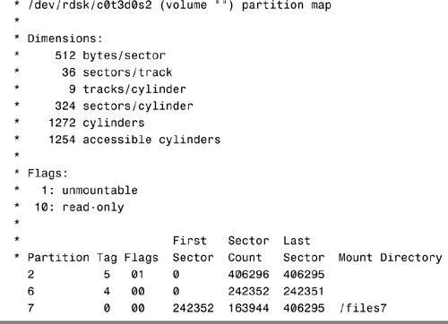
The prtvtoc command shows the number of cylinders and heads, as well as how the disk’s slices are arranged.
The following is an example of running the prtvtoc command on a SCSI disk with an EFI label:

Before you can create a file system on a disk, the disk must be formatted, and you must divide it into slices by using the Solaris format utility. Formatting involves two separate processes:
![]() Writing format information to the disk
Writing format information to the disk
![]() Completing a surface analysis, which compiles an up-to-date list of disk defects
Completing a surface analysis, which compiles an up-to-date list of disk defects
When a disk is formatted, header and trailer information is superimposed on the disk. When the format utility runs a surface analysis, the controller scans the disk for defects. It should be noted that defects and formatting information reduce the total disk space available for data. This is why a new disk usually holds only 90–95% of its capacity after formatting. This percentage varies according to disk geometry and decreases as the disk ages and develops more defects.
The need to perform a surface analysis on a disk drive has dropped as more manufacturers ship their disk drives formatted and partitioned. You should not need to perform a surface analysis within the format utility when adding a disk drive to an existing system unless you think disk defects are causing problems. The primary reason that you would use format is if you want to view or change the partitioning scheme on a disk.
Caution
Always Back Up Your Data Formatting and creating slices is a destructive process, so make sure user data is backed up before you start.
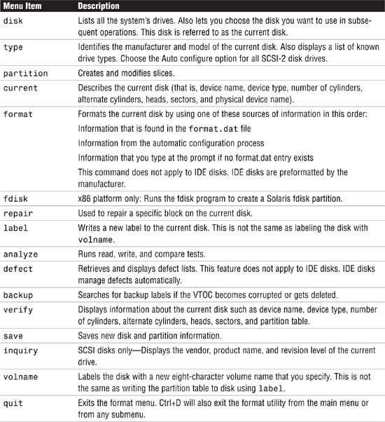
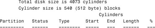
The format utility searches your system for all attached disk drives and reports the following information about the disk drives it finds:
In addition, the format utility is used in disk repair operations to do the following:
![]() Retrieve disk labels
Retrieve disk labels
![]() Repair defective sectors
Repair defective sectors
![]() Format and analyze disks
Format and analyze disks
![]() Partition disks
Partition disks
![]() Label disks (write the disk name and configuration information to the disk for future retrieval)
Label disks (write the disk name and configuration information to the disk for future retrieval)
The Solaris installation program partitions and labels disk drives as part of installing the Solaris release. However, you might need to use the format utility when doing the following:
![]() Displaying slice information
Displaying slice information
![]() Dividing a disk into slices
Dividing a disk into slices
![]() Formatting a disk drive when you think disk defects are causing problems
Formatting a disk drive when you think disk defects are causing problems
![]() Repairing a disk drive
Repairing a disk drive
The main reason a system administrator uses the format utility is to divide a disk into disk slices.
Exam Alert
format Utility Pay close attention to each menu item in the format utility and understand what task each performs. Expect to see several questions pertaining to the format utility menus on Exam CX-310-200. Along with adding slices, make sure you know how to remove or resize slices. You may see a scenario where a production system is running out of swap and you need to go into the format utility and add another swap slice.
The process of creating slices is outlined in Step by Step 1.3.
Note
If you are using Solaris on an x86 or x64-based PC system, refer to the next Step by Step to create an FDISK partition before creating the slices.
STEP BY STEP
1.3 Formatting a Disk
1. Become superuser.
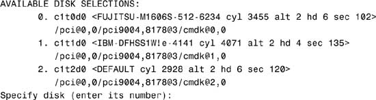
2. Type format.
The system responds with this:
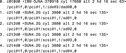
Searching for disks...done
AVAILABLE DISK SELECTIONS:
3. Specify the disk (enter its number).
The system responds with the format main menu:
FORMAT MENU:
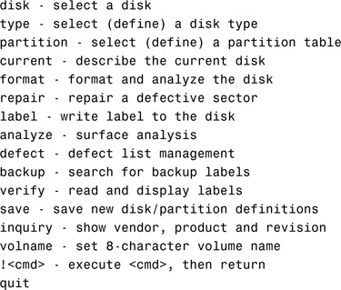
Table 1.5. describes the format main menu items.
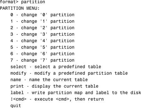
4. Type partition at the format prompt. The partition menu is displayed.
Note
Using Shortcuts in the format Utility It is unnecessary to type the entire command. After you type the first two characters of a command, the format utility recognizes the entire command.
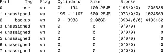
5. Type print to display the current partition map.
The system responds with this:
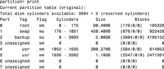
The columns displayed with the partition table are
![]() Part—The slice number (0–7).
Part—The slice number (0–7).
![]() Tag—This is an optional value that indicates how the slice is being used. The value can be any of the following names that best fits the function of the file system you are creating:
Tag—This is an optional value that indicates how the slice is being used. The value can be any of the following names that best fits the function of the file system you are creating:
unassigned, boot, root, swap, usr, backup, stand, var, home, alternates, reserved
You may also see tags labeled public or private, which represent Sun StorEdge Volume Manager tags:
![]() Flag—Values in this column can be
Flag—Values in this column can be
![]() wm—The disk slice is writable and mountable.
wm—The disk slice is writable and mountable.
![]() wu—The disk slice is writable and unmountable (such as a swap slice).
wu—The disk slice is writable and unmountable (such as a swap slice).
![]() rm—The disk slice is read-only and mountable.
rm—The disk slice is read-only and mountable.
![]() ru—The disk slice is read-only and unmountable.
ru—The disk slice is read-only and unmountable.
![]() Cylinders—The starting and ending cylinder number for the disk slice.
Cylinders—The starting and ending cylinder number for the disk slice.
![]() Size—The slice size specified as
Size—The slice size specified as
![]() mb—megabytes
mb—megabytes
![]() gb—gigabytes
gb—gigabytes
![]() b—blocks
b—blocks
![]() c—cylinders
c—cylinders
![]() Blocks—The total number of cylinders and the total number of sectors per slice.
Blocks—The total number of cylinders and the total number of sectors per slice.
Note
Wasted Disk Space Wasted disk space occurs during partitioning when one or more cylinders have not been allocated to a disk slice. This may happen intentionally or accidentally. If there are unallocated slices available, then wasted space can possibly be assigned to a slice later on.
You can use the name and save commands in the partition menu to name and save a newly created partition table to a file that can be referenced by name later, when you want to use this same partition scheme on another disk. When issuing the name command, you’ll provide a unique name for this partition scheme and then issue the save command to save the information to the ./format.dat file. Normally this file is located in the /etc directory, so provide the full pathname for /etc/format.dat to update the master file.
6. After you partition the disk, you must label it by typing label at the partition prompt:
partition> label
You are asked for confirmation on labeling the disk as follows:
Ready to label disk, continue?
Enter Y to continue.
Note
Label Your Drive To label a disk means to write slice information onto the disk. If you don’t label the drive when exiting the format utility, your partition changes will not be retained. Get into the habit of labeling at the partition submenu, but you can also label at the format utility main menu as well—you get two chances to remember before exiting the utility.
7. After labeling the disk, type quit to exit the partition menu:
partition> quit
8. Type quit again to exit the format utility:
format> quit
It’s important to point out a few undesirable things that can happen when defining disk partitions with the format utility if you’re not careful. First, be careful not to waste disk space. Wasted disk space can occur when you decrease the size of one slice and do not adjust the starting cylinder number of the adjoining disk slice.
Second, don’t overlap disk slices. Overlapping occurs when one or more cylinders are allocated to more than one disk slice. For example, increasing the size of one slice without decreasing the size of the adjoining slice will create overlapping partitions. The format utility will not warn you of wasted disk space or overlapping partitions.
As described earlier in this chapter, Solaris on x86-based PCs treats disk drives slightly differently than on the SPARC-based systems. On an x86 system, once a disk drive has been physically installed and verified as working, you’ll use the format command to slice the disk, but first an fdisk partition must be created on the new drive. Use the format command as follows:
STEP BY STEP
1.4 Using the format Command
1. As root, type format to get into the format utility.
format
The following menu appears:
2. Enter the number corresponding to the new drive and the following menu will be displayed:

3. Select the fdisk option and the following menu appears:
The recommended default partitioning for your disk is:
a 100% "SOLARIS System" partition.
To select this, please type "y". To partition your disk
differently, type "n" and the "fdisk" program will let you
select other partitions.
4. If you wish to use the entire drive for Solaris enter y. This will return to the format menu. If n is chosen, the fdisk menu will be displayed.
THERE ARE NO PARTITIONS CURRENTLY DEFINED
SELECT ONE OF THE FOLLOWING:
1. Create a partition
2. Change Active (Boot from) partition
3. Delete a partition
4. Exit (Update disk configuration and exit)
5. Cancel (Exit without updating disk configuration)
Enter Selection:
5. Choose 1 to create a Solaris FDISK partition. This is not the same as a Solaris slice.
6. After creating the partition, choose 4 to exit and save. The format menu will return.
7. Choose partition and follow the Step by Step 1.3 procedure described earlier for formatting a disk, beginning at step number 4.
One more item of note: On standard UFS file systems, don’t change the size of disk slices that are currently in use. When a disk with existing slices is repartitioned and relabeled, any existing data will be lost. Before repartitioning a disk, first copy all the data to tape or to another disk.
When using the format utility to change the size of disk slices, a temporary slice is automatically designated that expands and shrinks to accommodate the slice resizing operations. This temporary slice is referred to as the free hog, and it represents the unused disk space on a disk drive. If a slice is decreased, the free hog expands. The free hog is then used to allocate space to slices that have been increased. It does not, however, prevent the overlapping of disk slices as described in the previous section.
The free hog slice exists only when you run the format utility. It is not saved as a permanent slice.
If you need to change the size of slices on a particular disk, you can either re-create the disk slices as outlined in the previous section or use the modify option of the format utility.
Caution
Copy Your Data to Avoid Loss You will lose all data when changing partition sizes. Make sure that you copy your data either to another disk or to tape before continuing.
The modify option allows the root to create slices by specifying the size of each slice without having to keep track of starting cylinder boundaries. It also keeps track of any excess disk space in the temporary free hog slice. To modify a disk slice, follow the process outlined in Step by Step 1.5.
STEP BY STEP
1.5 Modifying a Disk Slice
1. Make a backup of your data. This process destroys the data on this disk slice.
2. As root, enter the partition menu of the format utility, as described in Step by Step 1.3.
3. After printing the existing partition scheme, type modify and press Enter.
Note
Mounted Partitions If you try to modify mounted partitions, you receive an error that states “Cannot modify disk partitions while it has mounted partitions.”
When typing modify, you’ll see the following output on a disk that does not have mounted partitions:
Select partitioning base:
0. Current partition table (original)
1. All Free Hog
Choose base (enter number) [0]?
4. Press Enter to select the default selection. The following is displayed:
Do you wish to continue creating a new partition
table based on above table[yes]?
5. Press Enter to select the default selection. The following message is displayed:
Free Hog partition[6]?
6. Press Enter to select the default selection. If all the disk space is in use, the following message is displayed:
Warning: No space available from Free Hog partition.
Continue[no]?
7. Type yes. You’ll be prompted to type the new size for each partition:
Enter size of partition '0' [205335b,195c,100.26mb,0.10gb]: 90m
Enter size of partition '1' [1024569b,973c,500.28mb 0.49gb]:450m
Enter size of partition '3' [0b, 0c, 0.00mb, 0.00gb]: <cr>
Enter size of partition '4' [0b, 0c, 0.00mb, 0.00gb]: <cr>
Enter size of partition '5' [0b, 0c, 0.00mb, 0.00gb]: <cr>
Enter size of partition '7' [0b, 0c, 0.00mb, 0.00gb]: <cr>
Note
Temporary Free Hog Slice 6 is not displayed because that is the temporary free hog.
When you are finished resizing the last partition, the following is displayed, showing you the revised partition map:
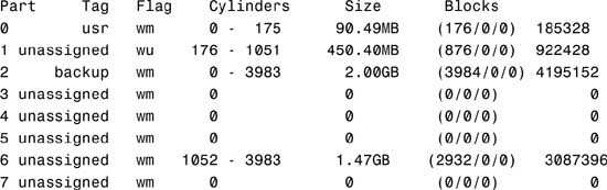
Okay to make this the current partition table[yes]?
Note
The Free Hog Slice 6, the free hog, represents the unused disk space. You might want to allocate this space to another partition so that it does not go unused, or you can save it and allocate it another time to an unused partition.
8. Press Enter to confirm your modified partition map. You’ll see the following message displayed:
Enter table name (remember quotes):
9. Name the modified partition table and press Enter:
Enter table name (remember quotes): c0t3d0.2gb
10. After you enter the name, the following message is displayed:
Ready to label disk, continue?
11. Type yes and press Enter to continue.
12. Type quit (or q) and press Enter to exit the partition menu. The main menu is displayed.
13. Type quit and press Enter to exit the format utility.
You can also partition a disk and view a disk’s partition information by using the graphical interface provided by the Solaris Management Console (SMC) Disks Tool. To view partition information, follow the procedure outlined in Step by Step 1.6.
STEP BY STEP
1.6 Viewing a Disk’s Partition Information Using Disks Tool
1. As root, start up the SMC by typing
smc &
2. In the left navigation window, select the This Computer icon, then click on the Storage icon as shown in Figure 1.2.
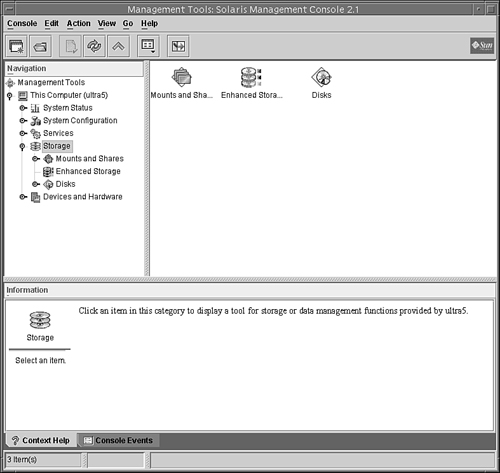
3. From the SMC Main window, select the Disks icon as shown in Figure 1.3.
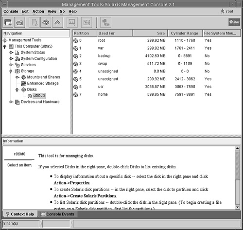
The disk drives connected to your system will be displayed in the main window as shown in Figure 1.4.
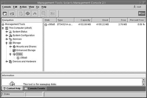
4. Select the disk that you wish to view and the partition information for that disk will be displayed as shown in Figure 1.5.
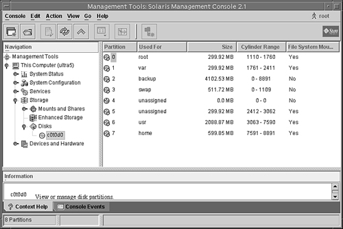
You can use the SMC Disks Tool to perform the following tasks:
![]() Display information about a specific disk.
Display information about a specific disk.
![]() Create Solaris disk partitions.
Create Solaris disk partitions.
![]() List partitions.
List partitions.
![]() Copy the layout of one disk to another disk of the same type.
Copy the layout of one disk to another disk of the same type.
![]() Change the disk’s label.
Change the disk’s label.
To partition a disk using the SMC Disks Tool, follow the steps outlined in Step by Step 1.6. After selecting the disk that you want to partition, select the Create Solaris Partitions option from the pull-down Action menu as shown in Figure 1.6.

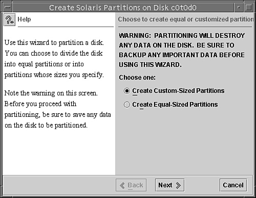
Click on the Next button and follow the prompts in each window to partition your disk. To partition a disk using the Disks Tool, follow the procedure outlined in Step by Step 1.7.
STEP BY STEP
1.7 Partitioning the Disk Using the SMC Disks Tool
1. In the window shown in Figure 1.7, specify whether you want to create custom-sized partitions or equal-sized partitions, then click the Next button. For this example, we are going to create custom-sized partitions. The window shown in Figure 1.8 will be displayed prompting you to specify the number of partitions to create.
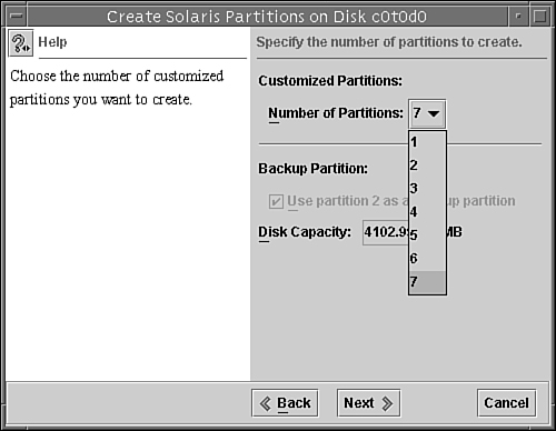
2. For this example, I selected 7 partitions and clicked on the Next button to continue. The next window prompts you to specify the size and use of the partition, as shown in Figure 1.9.
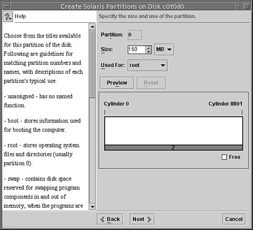
3. Next to the Size field, I selected MB and entered 150 into the Size field. Options for specifying size are MB (megabytes) or % (percentage of total disk).
For the Used For field, I selected root because this is going to be the root partition. Options are unassigned, boot, root, swap, usr, stand, var, or home. Select the option that matches the function of the file system that you are creating. These options are described in the “Using the format Utility to Create Slices” section of this chapter.
When you’ve made all of your selections, you can click on the Preview button to see a graphical layout of the disk. Click on the Next button when you are finished making all of your selections and you’ll be asked to specify the size and use of the next partition. Continue sizing each partition. For this example, I left the remaining slices at 0 MB.
4. When you are finished sizing all of your partitions, you’ll see a window summarizing all of your selections. Click Next and you’ll see a warning window displayed as shown in Figure 1.10.
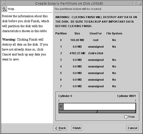
5. If you are satisfied with the partitions, click Finish. The new partitioning information is written and the newfs utility builds the partitions and creates each new file system.
It’s always a good idea to save a disk’s VTOC to a file using the prtvtoc command described earlier. This information can then be used later to restore the disk label if your current VTOC becomes corrupted or accidentally changed, or if you need to replace the disk drive.
Note
The disk label (VTOC) is stored in block 0 of each disk. The UFS file systems are smart enough not to touch the disk label, but be careful of any third party applications that create raw data slices. Ensure that these applications do not start at block 0; otherwise the disk label will be overwritten and the data on the disk will become inaccessible. I’ve seen some administrators start their raw slice at cylinder 2 or 3 just to ensure the disk label does not accidentally get overwritten.
By saving the output from the prtvtoc command into a file on another disk, you can reference it when running the fmthard command. The fmthard command updates the VTOC on hard disks. To recover a VTOC using fmthard, follow Step by Step 1.8.
STEP BY STEP
1.8 Recovering a VTOC
1. Run the format utility on the disk and label it with the default partition table.
2. Use the fmthard command to write the backup VTOC information back to the disk drive. The following example uses the fmthard command to recover a corrupt label on a disk named
/dev/rdsk/c0t3d0s2. The backup VTOC information is in a file named c0t3d0 in the /vtoc directory:
fmthard -s /vtoc/c0t3d0 /dev/rdsk/c0t3d0s2
Another use for the fmthard command is partitioning several disks with the same partitioning scheme. Get the VTOC information from the disk you want to copy (c0t0d0), and write the information to the new disk (c1t0d0) as follows:
prtvtoc /dev/rdsk/c0t0d0s0 | fmthard -s - /dev/rdsk/c1t0d0s2
On a large server with many disk drives, standard methods of disk slicing are inadequate and inefficient. File systems cannot span multiple disks, and the size of the file system is limited to the size of the disk. Another problem with standard file systems is that they cannot be increased in size without destroying data on the file system.
Sun has addressed these issues with two software packages: the Solaris Volume Manager (SVM), called Solstice DiskSuite in previous Solaris releases, and the Veritas Volume Manager (VxVM). Both packages allow file systems to span multiple disks and provide for improved I/O and reliability compared to the standard Solaris file system. We refer to these types of file systems as logical volumes (LVMs).
SVM is now part of Solaris 10. The Veritas Volume Manager is purchased separately and is not part of the standard Solaris operating system distribution. SVM is a lower cost solution and typically, SVM is used on Sun’s multipacks and for mirroring the OS drives, whereas the Veritas Volume Manager package is used on the larger SPARC storage arrays. LVMs, the SVM, and the Veritas Volume Manager are described in Chapter 10.
Tip
File Systems Although this section doesn’t apply to any specific exam objective, the information is provided to help you better understand file systems in general.
UFS is the default disk-based file system used by the Solaris operating environment. It provides the following features:
![]() State flags—These show the state of the file system as clean, stable, active, or unknown. These flags eliminate unnecessary file system checks. If the file system is clean or stable,
State flags—These show the state of the file system as clean, stable, active, or unknown. These flags eliminate unnecessary file system checks. If the file system is clean or stable, fsck (file system check) is not run when the system boots.
![]() Extended fundamental types (EFT)—These include a 32-bit user ID (UID), a group ID (GID), and device numbers.
Extended fundamental types (EFT)—These include a 32-bit user ID (UID), a group ID (GID), and device numbers.
![]() Large file systems—A UFS can be as large as 1 terabyte (TB) and can have regular files up to 2 gigabytes (GB). By default, the Solaris system software does not provide striping, which is required to make a logical slice large enough for a 1TB file system. However, the Solaris Volume Manager described in Chapter 10, provides this capability.
Large file systems—A UFS can be as large as 1 terabyte (TB) and can have regular files up to 2 gigabytes (GB). By default, the Solaris system software does not provide striping, which is required to make a logical slice large enough for a 1TB file system. However, the Solaris Volume Manager described in Chapter 10, provides this capability.
![]() By default, a UFS can have regular files larger than 2GB—You must explicitly use the
By default, a UFS can have regular files larger than 2GB—You must explicitly use the nolargefiles mount option to enforce a 2GB maximum file size limit.
![]() Logging—UFS logging is the process of writing file system updates to a log before applying the updates to a UFS file system.
Logging—UFS logging is the process of writing file system updates to a log before applying the updates to a UFS file system.
![]() Multiterabyte file systems—A multiterabyte file system enables creation of a UFS file system with up to approximately 16 terabytes of usable space, minus approximately one percent overhead. The system must be booted under a 64-bit kernel to support a multiterabyte file system. Systems booted under a 32-bit kernel are limited to a 1 TB file system.
Multiterabyte file systems—A multiterabyte file system enables creation of a UFS file system with up to approximately 16 terabytes of usable space, minus approximately one percent overhead. The system must be booted under a 64-bit kernel to support a multiterabyte file system. Systems booted under a 32-bit kernel are limited to a 1 TB file system.
During the installation of the Solaris software, several UFS file systems are created on the system disk. These are Sun’s default file systems. Their contents are described in Table 1.6.
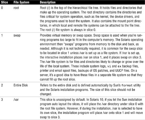

Slice Numbers and Their Location on Disk
Although root may be located on slice 0, it doesn’t necessarily mean that it is located first on the disk. For example, note the following partition scheme:

Notice how slice 3 starts at cylinder 0 and ends at cylinder 257. This puts slice 3 first on the disk. root is located on slice 0, which starts after slice 3 at cylinder 258. When using the interactive installation program to install the operating system, the swap partition is placed at the start of the disk beginning at cylinder 0 and the root partition is placed after the swap partition. A marginal performance increase is achieved by putting swap at the starting cylinder because of the faster rotation speeds on the outside perimeter of the disk. The interactive installation program is described in Chapter 2, “Installing the Solaris 10 Operating Environment.”
You need to create (or re-create) a UFS only when you do the following:
![]() Add or replace disks.
Add or replace disks.
![]() Change the slices of an existing disk.
Change the slices of an existing disk.
![]() Do a full restore on a file system.
Do a full restore on a file system.
![]() Change the parameters of a file system, such as block size or free space.
Change the parameters of a file system, such as block size or free space.
Objective:
Describe the purpose, features, and functions of root subdirectories, file components, file types, and hard links in the Solaris directory hierarchy.
Solaris comes with many file systems already created. These file systems were described earlier in this chapter. One of the most important file systems is the root file system. This file system is important because it is the first file system that is mounted when the system begins to boot. It is the file system that contains the kernel and all of the bootup scripts and programs. Without this file system, the system will not boot.
Furthermore, the root file system is at the top of the hierarchy of all file systems and contains all of the directory mount points for the other file systems. Taking a closer look at the contents of the root file system, we see that it contains many important directories, which are described in Table 1.7.
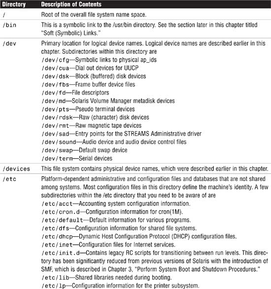

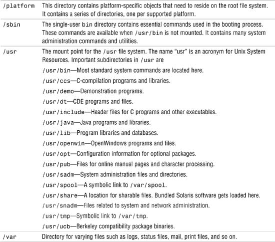
In addition, Solaris 10 introduces additional in-memory system directories and subdirectories that are described in Table 1.8. These in-memory directories are maintained by the kernel and system services. With the exception of /tmp, do not attempt to manually create, alter, or remove files from these directories.
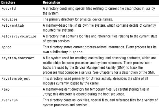
As you browse the directories in the root file system, you’ll notice many file types. The file type can usually be identified by looking at the first character of the first column of information displayed when issuing the ls -l command.
A typical listing may look like this when listing the contents of the /etc directory:
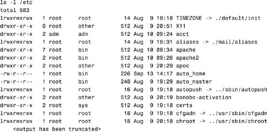
The information displayed in the long listing is in the form of columns and is as follows (reading from left to right):
![]() Column 1—Ten characters that describe the mode of the file. The first character displays the file type where
Column 1—Ten characters that describe the mode of the file. The first character displays the file type where
|
d |
The entry is a directory. |
|
D |
The entry is a door. |
|
l |
The entry is a symbolic link. |
|
b |
The entry is a block special file. |
|
c |
The entry is a character special file. |
|
p |
The entry is a FIFO (or “named pipe”) special file. |
|
s |
The entry is an AF_UNIX address family socket. |
|
- |
The entry is an ordinary file. |
The next nine characters in column one describe the file’s permission mode, which is described in detail in Chapter 4.
![]() Column 2—Displays the number of links to the file
Column 2—Displays the number of links to the file
![]() Column 3—Displays the file’s owner
Column 3—Displays the file’s owner
![]() Column 4—Displays the file’s group
Column 4—Displays the file’s group
![]() Column 5—Displays the file size in bytes
Column 5—Displays the file size in bytes
![]() Column 6—Date/Time of the file’s last modification
Column 6—Date/Time of the file’s last modification
![]() Column 7—File name
Column 7—File name
The -> after a file name denotes a symbolic link, as follows:
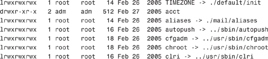
A link is a pointer to another file or directory. Links provide a mechanism for multiple file names to reference the same data on disk. In Solaris, there are two types of links:
Both of these are discussed in the following sections.
Sometimes symbolic links are used for shortcuts; other times we use them to link to a filename from each user’s home directory to a centralized location or file. For example, perhaps we want to have a common directory named documents where every user stores their documents. This directory exists as /export/data/documents. In each user’s directory, we create a link named documents that points to /export/data/documents. As a user, whenever I store something in the directory named $HOME/documents, the file actually gets directed to /export/data/documents. We can identify links when we perform a long listing on a directory as follows:
Note
Notice the use of the -i option used with the ls command and the results displayed. This option is used to display the inode number (in the left column of the output) that has been assigned to each file and directory. I’ll describe why this inode number is relevant to links later in this section when I describe hard links.

Notice the file that has an l as the first character of column 2. This is a soft or symbolic link. The sixth field shows a file size of 22 bytes and the last field shows which file or directory this link is pointing to. Each file has a unique inode number identified in column 1; the importance of this column is discussed later in this chapter.
When storing a file in $HOME/documents, the system is redirecting it to be stored in /export/data/documents. Now when changing to the /export/data directory and issuing the ls -li command:
cd /export/data
ls -li
The system displays the following:
![]()
Notice that the file that has a d as the first character of column 2. This is the directory that the $HOME/documents link points to. The first column shows the inode number, and the sixth column shows the file size as 512 bytes.
Symbolic links can point to files anywhere on the network. The file or directory could exist in another file system, on another disk, or on another system on the network.
The syntax for creating a symbolic link is as follows:
ln -s source-file link-name
For example, you might have a file named file1 that has the following contents:
This is the contents of file1
To create a symbolic link named link1, which will be linked to the existing file named file1, you issue the following command:
ln -s file1 link1
Now when you list the contents of the directory you see two files:
![]()
See the link named link1 pointing to file1? If you display the contents of link1, it shows the following:
This is the contents of file1
If you remove file1, the source file, link1 will still exist, but it points to a file that does not exist. Type the following:
cat link1
The cat command can’t print out the contents of the file, so you get this message:
cat: Cannot open link1
When you re-create file1, link1 will contain data again.
Objective:
Explain how to create and remove hard links in a Solaris directory.
A hard link is more difficult to determine, because they are not so obvious when viewed with the ls -li command. For example, when you go to the /etc/rc2.d directory and type
ls -li
the system displays the following:

The first character in the second column of information displays the file type as a regular file (-). The third column, link count, shows a number greater than 1. It displays the number of links used by this inode number. These are hard links, but they are not identified as links and the display does not show which file they are linked to.
Think of a hard link as a file that has many names. In other words, they all share the same inode number. As described in the section titled “The inode” later in this chapter, a file system identifies a file not by its name, but by its inode number. Looking at the file named S90wbem in the previous listing, we see an inode number of 1898. List all file names in this file system that share this inode number as follows:
find / -mount -inum 1898 -ls
The system displays the following list of files:
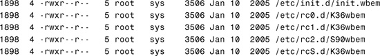
All six of these files have the same inode number; therefore, they are the same file. You can delete any one of the filenames, and the data will still exist.
In this example, the file is named file1 in $HOME:
![]()
The contents of this file are displayed with the cat command:
This is the contents of file1
The syntax for creating a hard link is as follows:
ln source-file link-name
To create a hard link named link1, which will be linked to the existing file named file1, issue the following command:
ln file1 link1
Now when I list the contents of the directory, I see two files:
![]()
Both files share the same inode number, the number of links is two, and the file size is 30 bytes. If I display the contents of link1, it shows the following:
This is the content of file1
If I remove file1, the source file, link1 still exists and still contains the data. The data will not be deleted until I destroy the last file that shares this inode number.
A hard link cannot span file systems; it can only point to another file located within its file system. The reason is that hard links all share an inode number. Each file system has its own set of inode numbers; therefore, a file with inode number 3588 in the /export/home file system may not even exist in the /var file system.
An advantage of a symbolic link over a hard link is that you can create a symbolic link to a file that does not yet exist. You cannot create a hard link unless the source file already exists. Here’s what happens when you create a symbolic link to a file that does not exist:
ln -s nonexistentfile link5
When you list the file:
ls -l link5
The system responds with
lrwxrwxrwx 1 bcalkins staff 14 Jun 17 18:24 link5 -> nonexistentfile
Now, here’s what happens when you create a hard link to a file that does not exist:
ln noexistentfile link6
The system responds with
ln: cannot access noexistentfile
Remove a link using the rm command as follows:
rm <linkname>
For example, to remove the link named link1, type
rm link1
Note
Removing Files and Links When you remove a file, it’s always a good idea to remove the symbolic links that pointed to that file, unless you plan to use them again if the file gets re-created.
Another advantage of symbolic links over hard links is that a symbolic link can link directories or files, whereas a hard link can link only files.
When you create a UFS, the disk slice is divided into cylinder groups. The slice is then divided into blocks to control and organize the structure of the files within the cylinder group. Each block performs a specific function in the file system. A UFS has the following four types of blocks:
![]() Boot block—Stores information used when booting the system
Boot block—Stores information used when booting the system
![]() Superblock—Stores much of the information about the file system
Superblock—Stores much of the information about the file system
![]() Cylinder Group—File systems are divided into cylinder groups to improve disk access.
Cylinder Group—File systems are divided into cylinder groups to improve disk access.
![]() Inode—Stores all information about a file except its name
Inode—Stores all information about a file except its name
![]() Storage or data block—Stores data for each file
Storage or data block—Stores data for each file
The boot block stores the code used in booting the system. Without a boot block, the system does not boot. Each file system has 15 sectors of space (sectors 1–15) allocated at the beginning for a boot block; however, if a file system is not to be used for booting, the boot block is left blank. The boot block appears only in the first cylinder group (cylinder group 0) and is the first 8KB in a slice.
The superblock resides in the 16 sectors (sectors 16–31) following the boot block and stores much of the information about the file system. Following are a few of the more important items contained in a superblock:
![]() Size and status of the file system
Size and status of the file system
![]() Label (file system name and volume name)
Label (file system name and volume name)
![]() Size of the file system’s logical block
Size of the file system’s logical block
![]() Date and time of the last update
Date and time of the last update
![]() Cylinder group size
Cylinder group size
![]() Number of data blocks in a cylinder group
Number of data blocks in a cylinder group
![]() Summary data block
Summary data block
![]() File system state (clean, stable, or active)
File system state (clean, stable, or active)
![]() Pathname of the last mount point
Pathname of the last mount point
Without a superblock, the file system becomes unreadable. Because it contains critical data, the superblock is replicated in each cylinder group and multiple superblocks are made when the file system is created.
A copy of the superblock for each file system is kept up-to-date in memory. If the system gets halted before a disk copy of the superblock gets updated, the most recent changes are lost and the file system becomes inconsistent. The sync command saves every superblock in memory to the disk. The file system check program fsck can fix problems that occur when the sync command hasn’t been used before a shutdown.
A summary information block is kept with the superblock. It is not replicated but is grouped with the first superblock, usually in cylinder group 0. The summary block records changes that take place as the file system is used, listing the number of inodes, directories, fragments, and storage blocks within the file system.
Each file system is divided into cylinder groups with a minimum default size of 16 cylinders per group. Cylinder groups improve disk access. The file system constantly optimizes disk performance by attempting to place a file’s data into a single cylinder group, which reduces the distance a head has to travel to access the file’s data.
An inode contains all the information about a file except its name, which is kept in a directory. A filename is associated with an inode, and the inode provides access to data blocks. An inode is 128 bytes. The inode information is kept in the cylinder information block and contains the following:
![]() The type of the file (regular, directory, block special, character special, link, and so on)
The type of the file (regular, directory, block special, character special, link, and so on)
![]() The mode of the file (the set of read/write/execute permissions)
The mode of the file (the set of read/write/execute permissions)
![]() The number of hard links to the file
The number of hard links to the file
![]() The user ID of the file’s owner
The user ID of the file’s owner
![]() The group ID to which the file belongs
The group ID to which the file belongs
![]() The number of bytes in the file
The number of bytes in the file
![]() An array of 15 disk-block addresses
An array of 15 disk-block addresses
![]() The date and time the file was last accessed
The date and time the file was last accessed
![]() The date and time the file was last modified
The date and time the file was last modified
![]() The date and time the file was created
The date and time the file was created
inodes are numbered and each file system maintains its own list of inodes. inodes are created for each file system when the file system is created. The maximum number of files per UFS is determined by the number of inodes allocated for a file system. The number of inodes depends on the amount of disk space that is allocated for each inode and the total size of the file system. Table 1.9 displays the default number of inodes created by the newfs command based on the size of the file system.
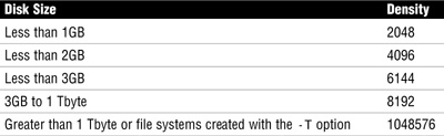
You can change the default allocation by using the -i option of the newfs command. Also, the number of inodes will increase if a file system is expanded with the growfs command. The newfs command is described later in this chapter and growfs is described in Chapter 10, “Managing Storage Volumes.”
Storage blocks, also called data blocks, occupy the rest of the space allocated to the file system. The size of these storage blocks is determined at the time a file system is created. Storage blocks are allocated, by default, in two sizes: an 8KB logical block size and a 1KB fragmentation size.
For a regular file, the storage blocks contain the contents of the file. For a directory, the storage blocks contain entries that give the inode number and the filename of the files in the directory.
Objective:
Explain when and how to create a new UFS using the newfs command, check the file system using fsck, resolve file system inconsistencies, and monitor file system usage using associated commands.
Use the newfs command to create UFS file systems. newfs is a convenient front end to the mkfs command, the program that creates the new file system on a disk slice.
On Solaris 10 systems, information used to set some of the parameter defaults, such as number of tracks per cylinder and number of sectors per track, is read from the disk label. newfs determines the file system parameters to use, based on the options you specify and information provided in the disk label. Parameters are then passed to the mkfs (make file system) command, which builds the file system. Although you can use the mkfs command directly, it’s more difficult to use and you must supply many of the parameters manually. (The use of the newfs command is discussed more in the next section.)
You must format the disk and divide it into slices before you can create a file system on it. newfs makes existing data on the disk slice inaccessible and creates the skeleton of a directory structure, including a directory named lost+found. After you run newfs, the slice is ready to be mounted as a file system.
Caution
Cleaning Sensitive Data from a Disk Removing a file system using the newfs or rm commands, or simply formatting the disk, is not sufficient to completely remove data bits from the disk. In order to wipe a hard disk clean of sensitive information, so that the data is beyond the recovery limits of any data recovery software or utility, use the analyze option within the format utility’s main menu. When the analyze menu appears, select the purge option. Purging data from the disk complies with Department of Defense (DoD) wipe disk standards for completely removing data bits from a disk. This procedure destroys all the file systems on the disk.
To create a UFS on a formatted disk that has already been divided into slices, you need to know the raw device filename of the slice that will contain the file system (see Step by Step 1.9). If you are re-creating or modifying an existing UFS, back up and unmount the file system before performing these steps.
STEP BY STEP
1.9 Creating a UFS
1. Become superuser.
2. Type newfs /dev/rdsk/<device-name> and press Enter. You are asked if you want to proceed. The newfs command requires the use of the raw device name, not the buffered device name. If the buffered device name is used, it will be converted to a raw device name. For more information on raw (character) and buffered (block) devices, refer to the “Block and Raw Devices” section that appeared earlier in this chapter.
Caution
Prevent Yourself from Erasing the Wrong Slice Be sure you have specified the correct device name for the slice before performing the next step. The newfs command is destructive and you will erase the contents of the slice when the new file system is created. Be careful not to erase the wrong slice.
3. Type y to confirm.
The following example creates a file system on /dev/rdsk/c2t1d0s1:
1. Become superuser by typing su, and enter the root password.
2. Type newfs /dev/rdsk/c2t1d0s1.
The system responds with this:

The newfs command uses conservative and safe default values to create the file system. We describe how to modify these values later in this chapter. Here are the default parameters used by the newfs command:
![]() The file system block size is 8192.
The file system block size is 8192.
![]() The file system fragment size (the smallest allocable unit of disk space) is 1024 bytes.
The file system fragment size (the smallest allocable unit of disk space) is 1024 bytes.
![]() The percentage of free space is now calculated as follows: (64MB/partition size) × 100, rounded down to the nearest integer and limited to between 1% and 10%, inclusive.
The percentage of free space is now calculated as follows: (64MB/partition size) × 100, rounded down to the nearest integer and limited to between 1% and 10%, inclusive.
![]() The number of inodes allocated to a file system (see Table 1.9, titled “Default Number of inodes”).
The number of inodes allocated to a file system (see Table 1.9, titled “Default Number of inodes”).
Before you choose to alter the default file system parameters assigned by the newfs command, you need to understand them. This section describes each of these parameters:
![]() Fragment size
Fragment size
![]() Minimum free space
Minimum free space
![]() Rotational delay (gap)
Rotational delay (gap)
![]() Optimization type
Optimization type
![]() Number of inodes and bytes per inode
Number of inodes and bytes per inode
The logical block size is the size of the blocks that the Unix kernel uses to read or write files. The logical block size is usually different from the physical block size (usually 512 bytes), which is the size of the smallest block that the disk controller can read or write.
You can specify the logical block size of the file system. After the file system is created, you cannot change this parameter without rebuilding the file system. You can have file systems with different logical block sizes on the same disk.
By default, the logical block size is 8192 bytes (8KB) for UFS file systems. The UFS supports block sizes of 4096 or 8192 bytes (4KB or 8KB, with 8KB being the recommended logical block size).
To choose the best logical block size for your system, consider both the performance desired and the available space. For most UFS systems, an 8KB file system provides the best performance, offering a good balance between disk performance and use of space in primary memory and on disk.
Note
sun4u Only The sun4u architecture does not support the 4KB block size.
As a general rule, a larger logical block size increases efficiency for file systems in which most of the files are large. Use a smaller logical block size for file systems in which most of the files are small. You can use the quot -c file system command on a file system to display a complete report on the distribution of files by block size.
As files are created or expanded, they are allocated disk space in either full logical blocks or portions of logical blocks called fragments. When disk space is needed to hold data for a file, full blocks are allocated first, and then one or more fragments of a block are allocated for the remainder. For small files, allocation begins with fragments.
The capability to allocate fragments of blocks to files rather than whole blocks saves space by reducing the fragmentation of disk space that results from unused holes in blocks.
You define the fragment size when you create a UFS. The default fragment size is 1KB. Each block can be divided into one, two, four, or eight fragments, resulting in fragment sizes from 512 bytes (for 4KB file systems) to 8192 bytes (for 8KB file systems only). The lower boundary is actually tied to the disk sector size, typically 512 bytes.
Note
Fragment Size for Large Files The upper boundary might equal the full block size, in which case the fragment is not a fragment at all. This configuration might be optimal for file systems with large files when you are more concerned with speed than with space.
When choosing a fragment size, look at the trade-off between time and space: A small fragment size saves space but requires more time to allocate. As a general rule, a larger fragment size increases efficiency for file systems in which most of the files are large. Use a smaller fragment size for file systems in which most of the files are small.
The minimum free space is the percentage of the total disk space held in reserve when you create the file system. Before Solaris 7, the default reserve was always 10%. Since Solaris 7, the minimum free space is automatically determined. This new method of calculating free space results in less wasted disk space on large file systems.
Free space is important because file access becomes less efficient as a file system gets full. As long as the amount of free space is adequate, UFS file systems operate efficiently. When a file system becomes full, using up the available user space, only root can access the reserved free space.
Commands such as df report the percentage of space available to users, excluding the percentage allocated as the minimum free space. When the command reports that more than 100% of the disk space in the file system is in use, some of the reserve has been used by root.
If you impose quotas on users, the amount of space available to the users does not include the free space reserve. You can change the value of the minimum free space for an existing file system by using the tunefs command.
The optimization type is either space or time. When you select space optimization, disk blocks are allocated to minimize fragmentation and optimize disk use.
When you select time optimization, disk blocks are allocated as quickly as possible, with less emphasis on their placement. With enough free space, the disk blocks can be allocated effectively with minimal fragmentation. Time is the default.
You can change the value of the optimization type parameter for an existing file system by using the tunefs command.
The number of inodes determines the number of files you can have in the file system because each file has one inode. The number of bytes per inode determines the total number of inodes created when the file system is made: the total size of the file system divided by the number of bytes per inode.
A file system with many symbolic links will have a lower average file size and the file system will require more inodes than a file system with a few very large files. If your file system will have many small files, you can use the -i option with newfs to specify the number of bytes per inode, which will determine the number of inodes in the file system. For a file system with very large files, give this parameter a lower value.
Note
Number of inodes Having too many inodes is much better than running out of them. If you have too few inodes, you could reach the maximum number of files on a disk slice that is practically empty.
Exam Alert
Expect to see several questions on creating, fixing, and managing file systems. All questions related to creating file systems will use newfs. It’s important to understand the file system options described in this mkfs section, but don’t be too concerned about understanding the mkfs method of creating file systems. Most system administrators use newfs and that is what you will be tested on.
Although it’s highly recommended that the newfs command be used to create file systems, it’s also important to see what is happening “behind the scenes” with the mkfs utility. The syntax for mkfs is as follows:
/usr/sbin/mkfs <options> <character device name>
The mkfs options are described in Table 1.10.
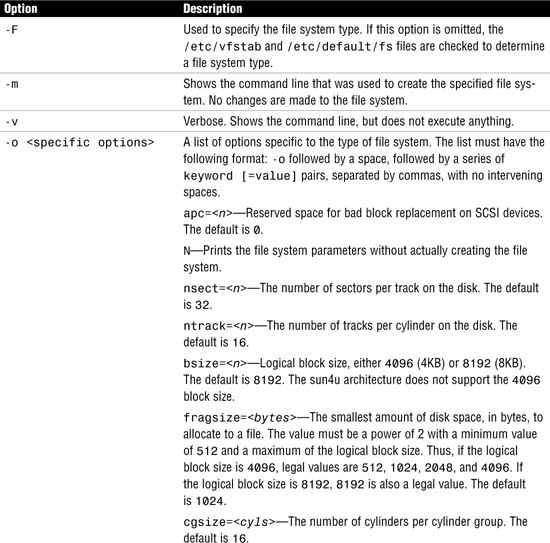
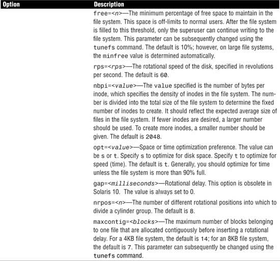
mkfs constructs a file system on the character (or raw) device found in the /dev/rdsk directory. Again, it is highly recommended that you do not run the mkfs command directly, but instead use the friendlier newfs command, which automatically determines all the necessary parameters required by mkfs to construct the file system. In the following example, the -v option to the newfs command outputs all the parameters passed to the mkfs utility. Type the following:
newfs -v /dev/rdsk/c2t4d0s1
The system outputs the following information and creates a new file system on /dev/rdsk/c2t4d0s1:
newfs: construct a new file system /dev/rdsk/c2t4d0s1: (y/n)? y
The following output appears on the screen:
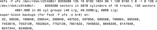
You’ll see in the output that all the mkfs parameters used to create the file system are displayed. The second line of output describes the disk. The third line describes the UFS file system being created. The remaining lines of output list the beginning sector locations of the backup superblocks.
The newfs command also creates a lost+found directory for the UFS file system. This directory is used by the fsck command and described later in this chapter.
A good command to use to view file system parameters is the fstyp command. Use the -v option to obtain a full listing of a file system’s parameters:
fstyp -v /dev/rdsk/c0t0d0s6
The system responds with this:
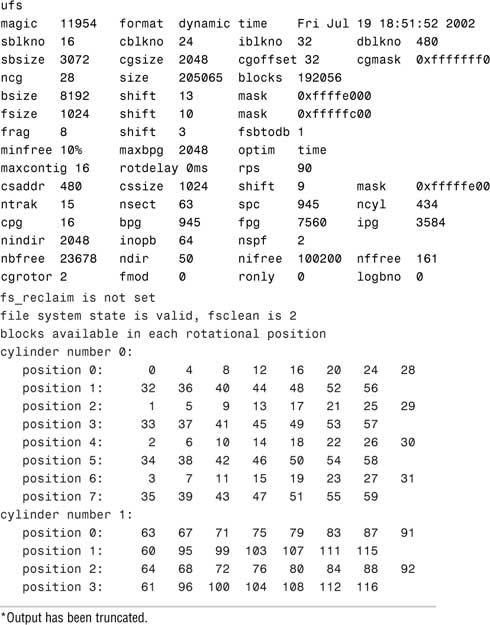
Note
Copy the mkfs Options It’s always a good idea to print the mkfs options used on a file system along with information provided by the prtvtoc command. Put the printout in your system log so that if you ever need to rebuild a file system because of a hard drive failure, you can re-create it exactly as it was before.
This section describes the Solaris utilities used for creating, checking, repairing, and mounting file systems. Use these utilities to make file systems available to the user and to ensure their reliability.
The UFS file system relies on an internal set of tables to keep track of inodes as well as used and available blocks. When a user performs an operation that requires data to be written to the disk, the data to be written is first copied into a buffer in the kernel. Normally, the disk update is not handled until long after the write operation has returned. At any given time, the file system, as it resides on the disk, might lag behind the state of the file system represented by the buffers located in physical memory (RAM). The internal tables finally get updated when the buffer is required for another use or when the kernel automatically runs the fsflush daemon (at 30-second intervals).
If the system is halted without writing out the memory-resident information, the file system on the disk will be in an inconsistent state. If the internal tables are not properly synchronized with data on the disk, inconsistencies result, data may be lost, and file systems will need repairing. File systems can be damaged or become inconsistent because of abrupt termination of the operating system in these ways:
![]() Experiencing power failure
Experiencing power failure
![]() Accidentally unplugging the system
Accidentally unplugging the system
![]() Turning off the system without the proper shutdown procedure
Turning off the system without the proper shutdown procedure
![]() Performing a Stop+A (L1+A)
Performing a Stop+A (L1+A)
![]() Encountering a software error in the kernel
Encountering a software error in the kernel
![]() Encountering a hardware failure that halts the system unexpectedly
Encountering a hardware failure that halts the system unexpectedly
To prevent unclean halts, the current state of the file system must be written to disk (that is, synchronized) before you halt the CPU or take a disk offline.
Exam Alert
Understand all aspects of repairing a file system. Know everything from unmounting a faulty file system, checking a file system, creating a new file system, and restoring data to that file system.
During normal operation, files are created, modified, and removed. Each time a file is modified, the operating system performs a series of file system updates. When a system is booted, a file system consistency check is automatically performed. Most of the time, this file system check repairs any problems it encounters. File systems are checked with the fsck (file system check) command.
Caution
Never run the fsck command on a mounted file system. This could leave the file system in an unstable state and could result in the loss of data. Because the / (root), /usr, and /var file systems cannot be unmounted, these file systems should only have fsck run on them while in single-user mode.
Reboot the system immediately after running the fsck on these mounted file systems.
The Solaris fsck command uses a state flag, which is stored in the superblock, to record the condition of the file system. Following are the possible state values:
![]()
FSCLEAN—If the file system was unmounted properly, the state flag is set to FSCLEAN. Any file system with an FSCLEAN state flag is not checked when the system is booted.
![]()
FSSTABLE—On a mounted file system, this state indicates that the file system has not changed since the last sync or fsflush. File systems marked as FSSTABLE can skip fsck before mounting.
![]()
FSACTIVE—The state flag gets set to FSACTIVE when a file system is mounted and modified. The FSACTIVE flag goes into effect before any modifications are written to disk, however. The exception is when a file system is mounted with UFS logging and the flag is set to FSLOG, as described later. When a file system is unmounted properly, the state flag is then set to FSCLEAN. A file system with the FSACTIVE flag must be checked by fsck because it might be inconsistent. The system does not mount a file system for read/write unless its state is FSCLEAN, FSLOG, or FSSTABLE.
![]()
FSBAD—If the root file system is mounted when its state is not FSCLEAN or FSSTABLE, the state flag is set to FSBAD. A root file system flagged as FSBAD as part of the boot process is mounted as read-only. You can run fsck on the raw root device and then remount the root file system as read/write.
![]()
FSLOG—If the file system was mounted with UFS logging, the state flag is set to FSLOG. Any file system with an FSLOG state flag is not checked when the system is booted. See the section titled “Mounting a File System with UFS Logging Enabled,” where I describe mounting a file system from the command line later in this chapter.
fsck is a multipass file system check program that performs successive passes over each file system, checking blocks and sizes, pathnames, connectivity, reference counts, and the map of free blocks (possibly rebuilding it). fsck also performs cleanup. The phases (passes) performed by the UFS version of fsck are described in Table 1.11.
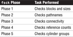
Normally, fsck is run noninteractively at bootup to preen the file systems after an abrupt system halt in which the latest file system changes were not written to disk. Preening automatically fixes any basic file system inconsistencies but does not try to repair more serious errors. While preening a file system, fsck fixes the inconsistencies it expects from such an abrupt halt. For more serious conditions, the command reports the error and terminates. It then tells the operator to run fsck manually.
File systems must be checked periodically for inconsistencies to avoid unexpected loss of data. As stated earlier, checking the state of a file system is automatically done at bootup; however, it is not necessary to reboot a system to check whether the file systems are stable as described in Step by Step 1.10.
STEP BY STEP
1.10 Determining the Current State of the File System
1. Become a superuser.
2. Type fsck -m /dev/rdsk/ cntndnsn and press Enter. The state flag in the superblock of the file system you specify is checked to see whether the file system is clean or requires checking. If you omit the device argument, all the UFS file systems listed in /etc/vfstab with an fsck pass value of greater than 0 are checked.
In the following example, the first file system needs checking, but the second file system does not:
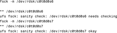
You might need to manually check file systems when they cannot be mounted or when you’ve determined that the state of a file system is unclean. Good indications that a file system might need to be checked are error messages displayed in the console window or system crashes that occur for no apparent reason.
When you run fsck manually, it reports each inconsistency found and fixes innocuous errors. For more serious errors, the command reports the inconsistency and prompts you to choose a response. Sometimes corrective actions performed by fsck result in some loss of data. The amount and severity of data loss can be determined from the fsck diagnostic output. The procedure outlined in Step by Step 1.11 describes how to check a file system by running the fsck command manually.
STEP BY STEP
1.11 Manually Checking File Systems
1. Log in as root and unmount the file system.
2. After the file system is unmounted, type fsck /dev/rdsk/<device> and press Enter.
If you do not specify a device, all file systems in the /etc/vfstab file with entries greater than 0 in the fsck pass field are checked, including root (/). As stated earlier, you must be in single-user mode to run fsck on root. You can also specify the mount point directory as an argument to fsck, and as long as the mount point has an entry in the /etc/vfstab file, fsck will be able to resolve the path to the raw device. The fsck command requires the raw device filename.
3. Any inconsistency messages are displayed. The only way to successfully change the file system and correct the problem is to answer yes to these messages.
Note
Supply an Automatic Yes Response to fsck The fsck command has a -y option that automatically answers yes to every question. But be careful: If fsck asks to delete a file, it will answer yes and you will have no control over it. If it doesn’t delete the file, however, the file system remains unclean and cannot be mounted.
4. If you corrected any errors, type fsck /dev/rdsk/<device> and press Enter. fsck might not be capable of fixing all errors in one execution. If you see the message FILE SYSTEM STATE NOT SET TO OKAY, run the command again and continue to run fsck until it runs clean with no errors.
5. Rename and move any files put in lost+found. Individual files put in the lost+found directory by fsck are renamed with their inode numbers, so figuring out what they were named originally can be difficult. If possible, rename the files and move them where they belong. You might be able to use the grep command to match phrases with individual files and use the file command to identify file types, ownership, and so on. When entire directories are dumped into lost+found, it is easier to figure out where they belong and move them back.
Note
Locating the Alternate Superblock Occasionally the file system’s superblock can become corrupted and fsck will ask you for the location of an alternate superblock. This information can be obtained by typing
newfs -Nv <raw device name>
After you create the file system with newfs, you can use the labelit utility to write or display labels on unmounted disk file systems. The syntax for labelit is as follows:
labelit <-F <fstype>> <-V> <special> <fsname volume>
Labeling a file system is optional. It’s required only if you’re using a program such as volcopy, which will be covered soon. The labelit command is described in Table 1.12.
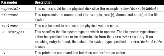
Note
View Current Labels If fsname and volume are not specified, labelit prints the current values of these labels. Both fsname and volume are limited to six or fewer characters.
The following is an example of how to label a disk partition using the labelit command. Type the following:
labelit -F ufs /dev/rdsk/c0t0d0s6 disk1 vol1
The system responds with this:
fsname: disk1
volume: vol1
The administrator (root) can use the volcopy command to make a copy of a labeled file system. This command works with UFS file systems, but the file system must be labeled with the labelit utility before the volcopy command is issued. To determine whether a file system is a UFS, issue this command:
fstyp /dev/rdsk/c0t0d0s6
The system responds with this:
ufs
The volcopy command can be used to copy a file system from one disk to another.
The syntax for volcopy is as follows:
volcopy <options> <fsname> <srcdevice> <volname1> <destdevice> <volname2>
volcopy is described in Table 1.13.
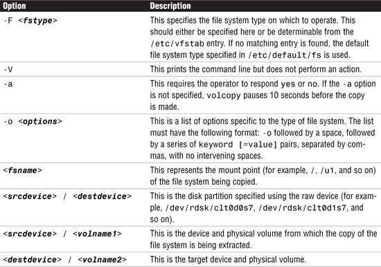
Note
fsname and volname Limits fsname and volname are limited to six or fewer characters and are recorded in the superblock. volname can be a dash (-) to use the existing volume name.
The following example copies the contents of /home1 (/dev/rdsk/c0t0d0s6) to /home2 (/dev/rdsk/c0t1d0s6):
volcopy -F ufs home1 /dev/rdsk/c0t0d0s6 home2 /dev/rdsk/c0t1d0s6 vol2
Other commands can also be used to copy file systems—ufsdump, cpio, tar, and dd, to name a few. These commands are discussed in Chapter 7, “Performing System Backups and Restorations.”
A situation might arise in which you want to change some of the parameters that were set when you originally created the file system. Perhaps you want to change the minfree value to free some additional disk space on a large disk drive. Using the tunefs command, you can modify the following file system parameters:
![]()
maxcontig
![]()
rotdelay
![]()
maxbpg
![]()
minfree
![]()
optimization
See Table 1.14 for a description of these options.
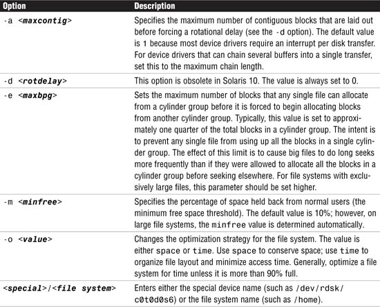
Caution
tunefs can destroy a file system in seconds. Always back up the entire file system before using tunefs.
The syntax for tunefs is as follows:
![]()
The tunefs command is described in Table 1.14.
The file system does not need to be unmounted before using tunefs.
To change the minimum free space (minfree) on a file system from 10% to 5%, type the following:
tunefs -m5 /dev/rdsk/c0t0d0s6
minimum percentage of free space changes from 10% to 5%
The manual page of tunefs recommends that minfree be set at 10%; if you set the value under that, you lose performance. This means that 10% of the disk is unusable. This might not have been too bad in the days when disks were a couple hundred megabytes in size, but on a 9GB disk, you’re losing 900MB of disk space. The mention of loss of performance in the manual page is misleading. With such large disk drives, you can afford to have minfree as low as 1%. This has been found to be a practical and affordable limit. In addition, performance does not become an issue because locating free blocks even within a 90MB area is efficient.
A rule of thumb is to use the default 10% minfree value for file systems up to 1GB and then adjust the minfree value so that your minfree area is no larger than 100MB. As for performance, applications do not complain about the lower minfree value. The one exception is the root (/) file system, in which the system administrator can use his judgment to allow more free space just to be conservative, in case root (/) ever becomes 100% full.
Note
Viewing the minfree Value On large file systems, the minfree is automatically determined so that disk space is not wasted. Use the mkfs -m command described next if you want to see the actual minfree value that newfs used.
Later, if you want to see what parameters were used when creating a file system, issue the mkfs command:
mkfs -m /dev/rdsk/c2t1d0s1
The system responds with this:
![]()
Objective:
Explain how to perform mounts and unmounts.
File systems can be mounted from the command line by using the mount command. The commands in Table 1.15 are used from the command line to mount and unmount file systems.

Note
/sbin/mountall is actually a shell script that first checks the state of each file system specified in the /etc/vfstab file before issuing the mount -a command. If the file system flag indicates that the file system is not mountable, mountall will prompt for the root password on the console and try to fix the file system with fsck before running the mount -a command.
After you create a file system, you need to make it available. You make file systems available by mounting them. Using the mount command, you attach a file system to the system directory tree at the specified mount point, and it becomes available to the system. The root file system is mounted at boot time and cannot be unmounted. Any other file system can be mounted or unmounted from the root file system with few exceptions.
The syntax for mount is as follows:
![]()
Table 1.16 describes options to the mount command.

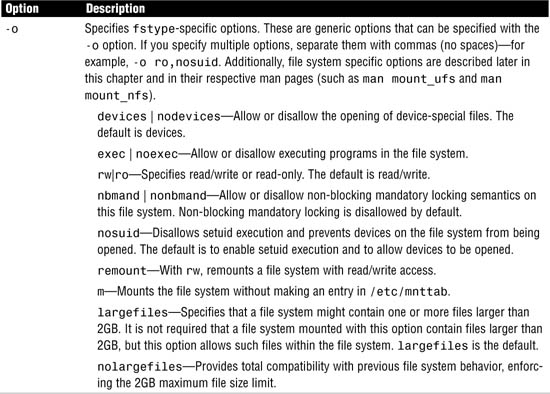
Note
Determining a File System’s Type Because the mount commands need the file system type to function properly, the file system type must be explicitly specified with the -F option or determined by searching the following files:
/etc/vfstab—Search the FS type field for the file system type.
/etc/default/fs—Search for a local file system type.
/etc/dfs/fstypes—Search for a remote file system type.
If the file system type is not found in any of these locations, the system will report an error.
Exam Alert
Be very familiar with the mount options for a UFS file system along with the defaults used when an option is not specified. The exam has several questions related to creating and repairing file systems. You need to know all aspects of mounting and unmounting a file system on a production (active) system.
The following examples illustrate the options described in Table 1.16.
A file system has been created on disk c0t0d0 on slice s0. The directory to be mounted on this disk slice is /home2. To mount the file system, first create the directory called /home2 and then type the following:
mount /dev/dsk/c0t0d0s0 /home2
If the file system has been mounted, you return to a command prompt. No other message is displayed.
When the UFS file system is mounted with no options, a default set of file system specific options are used—they are explained in Table 1.17. Options specific to the UFS file system are also described in the mount_ufs man pages.
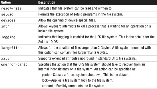
In the next example, the -v option is used with the mount command to display a list of all mounted file systems:
mount -v
The system responds with this:
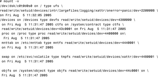

The following example mounts a file system as read-only:
mount -o ro /dev/dsk/c0t0d0s0 /home2
The next example uses the mount command to mount a directory to a file system as read/writeable, disallow setuid execution, and allow the creation of large files:
mount -o rw,nosuid,largefiles /dev/dsk/c0t0d0s0 /home2
Type mount with no options to verify that the file system has been mounted and to review the mount options that were used:
mount
The system responds with information about all mounted file systems, including /home2:
/home2 on /dev/dsk/c0t0d0s0 read/write/nosuid/largefiles on
Tue Jul 16 06:56:33 2005
Note
Using SMC to View Current Mounts You can also use the SMC Mounts Tool to view information about mounted file systems. The information provided is similar to the information displayed when you issue the mount command with no options. To access the Mounts Tool, follow the Step by Step procedure for using the SMC Usage Tool described in the section titled “Displaying a File System’s Disk Space Usage.”
On a Solaris system, a large file is a regular file whose size is greater than or equal to 2GB. A small file is a regular file whose size is less than 2GB. Some utilities can handle large files, and others cannot. A utility is called large file–aware if it can process large files in the same manner that it does small files. A large file–aware utility can handle large files as input and can generate large files as output. The newfs, mkfs, mount, umount, tunefs, labelit, and quota utilities are all large file–aware for UFS file systems.
Note
Due to file system overhead, the largest file size that can be created on a multiterabyte file system is approximately 1 Tbyte. The data capacity of a 1 Tbyte file system is approximately 1 Tbyte minus 0.5% overhead and the recommended 1% free space.
On the other hand, a utility is called large file–safe if it causes no data loss or corruption when it encounters a large file. A utility that is large file–safe cannot properly process a large file, so it returns an appropriate error. Some examples of utilities that are not large file–aware but are large file–safe include the vi editor and the mailx and lp commands. A full list of commands that are large file–aware and large file–safe can be found in the online manual pages.
The largefiles mount option lets users mount a file system containing files larger than 2GB. The largefiles mount option is the default state for the Solaris 10 environment. The largefiles option means that a file system mounted with this option might contain one or more files larger than 2GB.
You must explicitly use the nolargefiles mount option to disable this behavior. The nolargefiles option provides total compatibility with previous file system behavior, enforcing the 2GB maximum file size limit.
Note
Mounting Largefile File Systems After you mount a file system with the default largefiles option and large files have been created, you cannot remount the file system with the nolargefiles option until you remove any large files and run fsck to reset the state to nolargefiles.
The UFS logging feature eliminates file system inconsistency, which can significantly reduce the time of system reboots. UFS logging is the default in Solaris 10 and does not need to be specified when mounting a file system. Use the nologging option in the /etc/vfstab file or as an option to the mount command to disable UFS logging on a file system.
UFS logging is the process of storing file system operations to a log before the transactions are applied to the file system. Because the file system can never become inconsistent, fsck can usually be bypassed, which reduces the time to reboot a system if it crashes or after an unclean halt.
The UFS log is allocated from free blocks on the file system. It is sized at approximately 1MB per 1GB of file system, up to a maximum of 64MB. The default is logging for all UFS file systems.
Note
fsck on Logged File Systems Is it ever necessary to run fsck on a file system that has UFS logging enabled? The answer is yes. It is usually unnecessary to run fsck on a file system that has UFS logging enabled. The one exception to this is when the log is bad. An example of this is when a media failure causes the log to become unusable. In this case, logging puts the file system in an error state, and you cannot mount it and use it until fsck is run. The safest option is to always run fsck. It will quit immediately if logging is there and the file system is not in an error state.
Unmounting a file system removes it from the file system mount point and deletes the entry from /etc/mnttab. Some file system administration tasks, such as labelit and fsck, cannot be performed on mounted file systems. You should unmount a file system if any of the following three conditions exist:
![]() The file system is no longer needed or has been replaced by a file system that contains software that is more current.
The file system is no longer needed or has been replaced by a file system that contains software that is more current.
![]() When you check and repair it by using the
When you check and repair it by using the fsck command.
![]() When you are about to do a complete backup of it.
When you are about to do a complete backup of it.
To unmount a file system, use the umount command:
umount <mount-point>
<mount-point> is the name of the file system you want to unmount. This can be either the directory name in which the file system is mounted or the device name path of the file system. For example, to unmount the /home2 file system, type the following:
umount /home2
Alternatively, you can specify the device name path for the file system:
umount /dev/dsk/c0t0d0s0
Note
Shutting Down the System File systems are automatically unmounted as part of the system shutdown procedure.
Before you can unmount a file system, you must be logged in as the administrator (root) and the file system must not be busy. A file system is considered busy if a user is in a directory in the file system or if a program has a file open in that file system. You can make a file system available for unmounting by changing to a directory in a different file system or by logging out of the system. If something is causing the file system to be busy, you can use the fuser command, described in Table 1.18, to list all the processes that are accessing the file system and to stop them if necessary.

Note
Informing Users Always notify users before unmounting a file system.
The syntax for fuser is as follows:
/usr/sbin/fuser [options] <file>|<file system>
Replace <file> with the filename you are checking, or replace <file system> with the name of the file system you are checking.
The following example uses the fuser command to find out why /home2 is busy:
fuser -cu /home2
The system displays each process and user login name that is using this file system:
/home2: 8448c(root) 8396c(root)
The following command stops all processes that are using the /home2 file system by sending a SIGKILL to each one. Don’t use it without first warning the users:
fuser -c -k /home2
Using the fuser command as described is the preferred method for determining who is using a file system before unmounting it. Added in Solaris 8 was another, less desirable method for unmounting a file system, using the umount command with the -f option, as follows:
umount -f /home2
The -f option forcibly unmounts a file system. Using this option can cause data loss for open files and programs that access files after the file system has been unmounted; it returns an error (EIO). The -f option should be used only as a last resort.
You can also use the fuser command to check on any device such as the system console. By typing:
fuser /dev/console
The system displays the processes associated with that device as follows:
/dev/console: 459o 221o
When a file system is mounted, an entry is maintained in the mounted file system table called /etc/mnttab. The file /etc/mnttab is really a file system that provides read-only access to the table of mounted file systems for the current host. The mount command adds entries to this table, and umount removes entries from this table. The kernel maintains the list in order of mount time. For example, the first mounted file system is first in the list, and the most recently mounted file system is last. When mounted on a mount point, the file system appears as a regular file containing the current mnttab information. Each entry in this table is a line of fields separated by spaces in this form:
<special> <mount_point> <fstype> <options> <time>
Table 1.19 describes each field.

Following is a sample /etc/mnttab file:
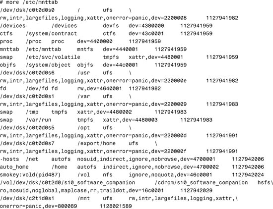
Before Solaris 8, the /etc/mnttab file was a text file. The downside of being a text file was that it could get out of sync with the actual state of mounted file systems, or it could be manually edited. Now this file is a mntfs file system that provides read-only information directly from the kernel about mounted file systems for the local hosts.
You can display the contents of the mount table by using the cat or more commands, but you cannot edit them.
You can also view a mounted file system by typing /sbin/mount from the command line as shown earlier in this section.
Objective:
Explain the purpose and function of the vfstab file in mounting UFS file systems, and the function of the mnttab file system in tracking current mounts.
The /etc/vfstab (virtual file system table) file contains a list of file systems, with the exception of the /etc/mnttab and /var/run, to be automatically mounted when the system is booted to the multiuser state. The system administrator places entries in the file, specifying what file systems are to be mounted at bootup. The following is an example of the /etc/vfstab file:

Exam Alert
You’ll need to make entries in the vfstab file on the exam. Understand the syntax and know how to create a new line in this file for both a UFS file system and swap.
Each column of information follows this format:
![]() device to mount—The buffered device that corresponds to the file system being mounted.
device to mount—The buffered device that corresponds to the file system being mounted.
![]() device to
device to fsck—The raw (character) special device that corresponds to the file system being mounted. This determines the raw interface used by fsck. Use a dash (-) when there is no applicable device, such as for swap, /proc, tmp, or a network-based file system.
![]() mount point—The default mount point directory.
mount point—The default mount point directory.
![]() FS type—The type of file system.
FS type—The type of file system.
![]()
fsck pass—The pass number used by fsck to decide whether to check a file. When the field contains a 0 or a non-numeric value, the file system is not checked. When the field contains a value of 1, the fsck utility gets started for that entry and runs to completion. When the field contains a value greater than 1, that device is added to the list of devices to have the fsck utility run. The fsck utility can run on up to eight devices in parallel. This field is ignored by the mountall command.
![]() mount at boot—Specifies whether the file system should be automatically mounted when the system is booted. These file systems get mounted when SMF starts up the
mount at boot—Specifies whether the file system should be automatically mounted when the system is booted. These file systems get mounted when SMF starts up the svc:/system/file system service instances.
Note
vfstab Entries for root (/), /usr, and /var For root (/), /usr, and /var file systems (if they are separate file systems), the mount at boot field option is no. The kernel mounts these file systems as part of the boot sequence before the mountall command is run. The mount command explicitly mounts the file systems root (/), /usr, and /var when SMF starts up the svc:/system/file system service instances.
![]()
mount options—A list of comma-separated options (with no spaces) used when mounting the file system. Use a dash (-) to use default mount options.
Type the mount command with the -p option to display a list of mounted file systems in /etc/vfstab format:
mount -p
The system responds with this:
/dev/dsk/c0t0d0s0 - / ufs - no rw,intr,largefiles,logging,xattr,onerror=panic
/devices - /devices devfs - no
ctfs - /system/contract ctfs - no
proc - /proc proc - no
mnttab - /etc/mnttab mntfs - no
swap - /etc/svc/volatile tmpfs - no xattr
objfs - /system/object objfs - no
/dev/dsk/c0t0d0s6 - /usr ufs - no rw,intr,largefiles,logging,xattr,onerror=panic
fd - /dev/fd fd - no rw
/dev/dsk/c0t0d0s1 - /var ufs - no rw,intr,largefiles,logging,xattr,onerror=panic
swap - /tmp tmpfs - no xattr
swap - /var/run tmpfs - no xattr
/dev/dsk/c0t0d0s4 - /data ufs - no rw,intr,largefiles,logging,xattr,onerror=panic
/dev/dsk/c0t0d0s5 - /opt ufs - no rw,intr,largefiles,logging,xattr,onerror=panic
/dev/dsk/c0t0d0s7 - /export/home ufs - no rw,intr,largefiles,logging,xattr,
onerror=panic
The -p option is useful for obtaining the correct settings if you’re making an entry in the /etc/vfstab file.
Objective:
Explain how to perform access or restrict access to mounted diskettes and CD-ROMs.
Volume management (not to be confused with Solaris Volume Manager [SVM] described in Chapter 10) with the vold daemon is the mechanism that manages removable media, such as the CD-ROM and floppy disk drives.
Mounting and unmounting a file system requires root privileges. How do you let users insert, mount, and unmount CD-ROMs and USB flash disks without being the administrator (root)? After a file system has been mounted and you remove the medium, what happens to the mount? Usually when you disconnect a disk drive while it is mounted, the system begins displaying error messages. The same thing happens if you remove a flash disk or CD-ROM while it is mounted.
Volume manager, with its vold daemon, provides assistance to overcome these problems. The vold daemon simplifies the use of disks and CDs by automatically mounting them. Volume manager provides three major benefits:
![]() By automatically mounting removable disks and CDs, volume management simplifies their use.
By automatically mounting removable disks and CDs, volume management simplifies their use.
![]() Volume manager enables the user to access removable disks and CDs without having to be logged in as root.
Volume manager enables the user to access removable disks and CDs without having to be logged in as root.
![]() Volume manager lets the administrator (root) give other systems on the network automatic access to any removable disks and CDs that the users insert into your system.
Volume manager lets the administrator (root) give other systems on the network automatic access to any removable disks and CDs that the users insert into your system.
To begin, let’s look at the two devices that the system administrator needs to manage: the floppy disk drive and the CD-ROM. Volume manager provides access to both devices through the /vol/dev directory. In addition, Volume Manager creates links to the removable disk, CD-ROM, and USB devices through various directories, as shown in Table 1.20.
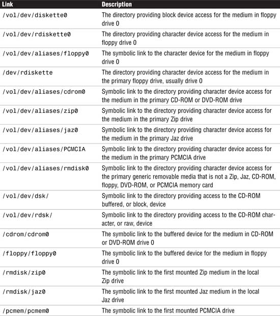
The vold daemon automatically creates the mount point and mounts file systems when removable media containing recognizable file systems are inserted into the devices. For example, when a CD is inserted, vold automatically creates a mount point in the /cdrom directory and mounts the CD-ROM file system onto this mount point. It then creates a symbolic link to /vol/dev/aliases/cdrom0 and /cdrom/cdrom0 as described in the previous table.
Note
Most CDs and DVDs are formatted to the ISO 9660 standard, which is portable. So, most CDs and DVDs can be mounted by volume management. However, CDs or DVDs with UFS file systems are not portable between architectures. So, they must be used on the architecture for which they were designed. For example, a CD or DVD with a UFS file system for a SPARC platform cannot be recognized by an x86 platform. Likewise, an x86 UFS CD cannot be mounted by volume management on a SPARC platform. The same limitation generally applies to diskettes. However, some architectures share the same bit structure, so occasionally a UFS format specific to one architecture will be recognized by another architecture. Still, the UFS file system structure was not designed to guarantee this compatibility.
With a removable disk, however, the file system is not automatically mounted until you issue the volcheck command. The volcheck command instructs vold to look at each device and determine whether new media has been inserted into the drive. On some removable disks such as floppy disks, vold cannot continually poll the disk drive like it does on a CD because of the hardware limitation in these removable drives. Continuously polling a removable disk for media causes a mechanical action in the disk drive and causes the drive to wear out prematurely.
All USB devices are hot-pluggable, which means that the device is added and removed without shutting down the OS or the power. USB storage devices will be mounted by vold without any user interaction. When you hot-plug a USB device, the device is immediately seen in the system’s device hierarchy, as displayed in the prtconf command output. When you remove a USB device, the device is removed from the system’s device hierarchy, unless the device is in use.
If the USB device is in use when it is removed, the device node remains, but the driver controlling this device stops all activity on the device. Any new I/O activity issued to this device is returned with an error. In this situation, the system prompts you to plug in the original device. If the device is no longer available, stop the applications. After a few seconds, the port becomes available again.
The rmformat command is used to format, label, partition, and perform various functions on removable media such as USB storage devices. For example, to use the rmformat command to format a Zip drive, type the following:
rmformat -F quick /vol/dev/aliases/zip0
The system displays the following information:
Formatting will erase all the data on disk.
Do you want to continue? (y/n) y
...........................................
The -F option is used with one of the following options:
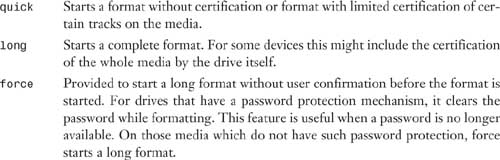
After formatting the device, you can use the newfs command to create a file system on the device as follows:
/usr/sbin/newfs -v /vol/dev/aliases/zip0
You can also use the rmformat -l command to list the removable media devices on the system. Using this command provides detailed information about the device, such as the name used by vold and both the logical and physical device names as follows:
rmformat -l
The system displays the following information:
Looking for devices...
1. Volmgt Node: /vol/dev/aliases/rmdisk1
Logical Node: /dev/rdsk/c5t0d0s2
Physical Node: /pci@1e,600000/usb@b/hub@2/storage@4/disk@0,0
Connected Device: TEAC FD-05PUB 1026
Device Type: Floppy drive
The vold daemon is the workhorse behind Volume Manager. It is automatically started by the /etc/init.d/volmgt script. vold reads the /etc/vold.conf configuration file at startup. The vold.conf file contains the Volume Manager configuration information. This information includes the database to use, labels that are supported, devices to use, actions to take if certain media events occur, and the list of file systems that are unsafe to eject without unmounting. The vold.conf file looks like this:
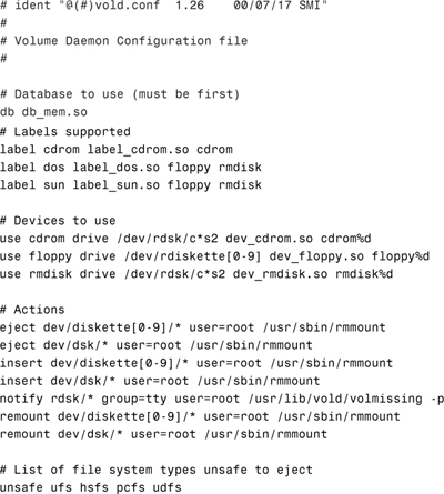
Each section in the vold.conf file is labeled with its function. Of these sections, you can safely modify the devices to use, which are described in Table 1.21, and actions, which are described in Table 1.22.
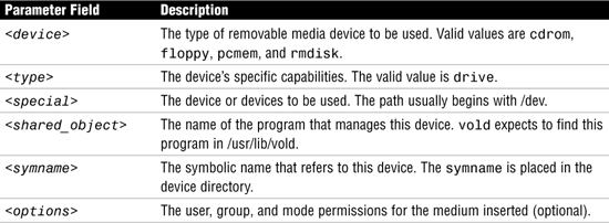

The “Devices to Use” section of the file describes the devices for vold to manage. vold has the following syntax:
use <device> <type> <special> <shared_object> <symname> <options>
The <special> and <symname> parameters are related. If <special> contains any shell wildcard characters (that is, has one or more asterisks or question marks in it), <symname> must have a %d at its end. In this case, the devices that are found to match the regular expression are sorted and then numbered. The first device has a 0 filled in for the %d, the second device found has a 1, and so on.
If the special specification does not have shell wildcard characters, the symname parameter must explicitly specify a number at its end.
The “Actions” section of the file specifies which program should be called if a particular event (action) occurs. The syntax for the Actions field is as follows:
insert <regex> <options> <program> <program_args>
eject <regex> <options> <program> <program_args>
notify <regex> <options> <program> <program_args>
The different actions are listed in Table 1.22.
In the default vold.conf file, you see the following entries under the “Devices to Use” and “Actions” sections:
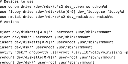
When a CD is inserted into the CD-ROM named /dev/dsk/c0t6d0, the following happens:
1. vold detects that the CD has been inserted and runs the /usr/sbin/rmmount command. rmmount is the utility that automatically mounts a file system on a CD-ROM and floppy. It determines the type of file system, if any, that is on the medium. If a file system is present, rmmount creates a mount point in the /cdrom directory and mounts the CD-ROM file system onto this mount point. It then creates a symbolic link to /vol/dev/aliases/cdrom0 and /cdrom/cdrom0 as described in the previous table.
If the medium is read-only (either a CD-ROM or a floppy with the write-protect tab set), the file system is mounted as read-only. If a file system is not identified, rmmount does not mount a file system.
2. After the mount is complete, the action associated with the media type is executed. The action allows other programs to be notified that a new medium is available. For example, the default action for mounting a CD-ROM or a floppy is to start the File Manager.
These actions are described in the configuration file /etc/rmmount.conf. Following is an example of the default /etc/rmmount.conf file:
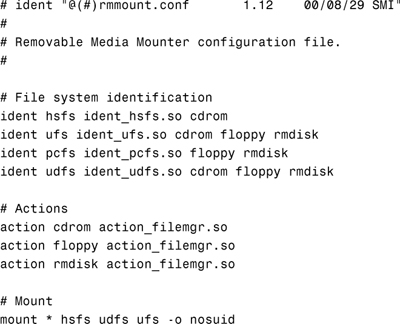
3. If the user issues the eject command, vold sees the media event and executes the action associated with that event. In this case, it runs /usr/sbin/rmmount. rmmount unmounts mounted file systems and executes actions associated with the media type called out in the /etc/rmmount.conf file. If a file system is “busy” (that is, it contains the current working directory of a live process), the eject action fails.
The system administrator can modify vold.conf to specify which program should be called if media events happen, such as eject or insert. If the vold.conf configuration file is modified, vold must be told to reread the /etc/vold.conf file. Signal vold to re-read the configuration file by sending a -HUP signal to the process as follows:
pkill -HUP vold
Several other commands help you administer Volume Manager on your system. They are described in Table 1.23.

To some, volume management might seem like more trouble than it’s worth. To disable volume management, remove (or rename) the file /etc/rc3.d/S81volmgt. Then issue the command /etc/init.d/volmgt stop. If you want to have volume management on the CD but not the floppy disk, comment out the entries in the “Devices to Use” and “Actions” sections of the vold.conf file with a #, as follows:
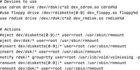
With the changes made to /etc/vold.conf, when the vold daemon starts up, it manages only the CD-ROM and not the floppy disk.
vold is picky. Knowing this is the key to keeping vold from crashing or not working for some reason. With other computers, such as Windows PCs, you can eject CD-ROMs with no problems. With Solaris, vold isn’t that robust, so the system administrator needs to follow a few ground rules when using volume management:
![]() Always use
Always use vold commands for everything to do with CD-ROMs and floppy disks. Use the commands listed in Table 1.23 to accomplish your task.
![]() Never press the button to eject a CD when a CD is already in the machine. This could cause
Never press the button to eject a CD when a CD is already in the machine. This could cause vold to stop working. Use the eject cdrom command instead.
![]() If you can’t stop or start
If you can’t stop or start vold using the /etc/init.d/volmgt script, you need to restart the system to get vold working properly.
I have found that the most reliable way to use floppy disks is via the Removable Media Manager GUI in the Common Desktop Environment (CDE) or Java Desktop Environment (JDE). Problems seem to be minimized when using floppy disks if I go through the media manager GUI versus the command line. Step by Step 1.12 describes how to access the Removable Media Manager GUI.
STEP BY STEP
1.12 Accessing the Removable Media Manager GUI
1. Open the File Manager GUI from the CDE front panel located at the bottom of the screen, as shown in Figure 1.11.

The File Manager appears.
2. Click the File menu located in the menu bar, as shown in Figure 1.12.

A pull-down menu will appear.
3. Select Removable Media Manager from the pull-down menu. The Removable Media Manager appears, as shown in Figure 1.13.
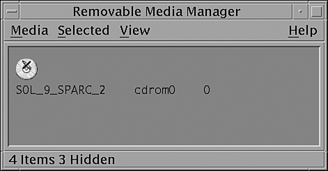
You might have problems with mounting a floppy or a CD-ROM. First, check to see if Volume Manager knows about the device. The best way to do this is to look in /vol/dev/rdiskette0 and see if something is there. If not, the volcheck command has not been run or a hardware problem exists. If references to /vol lock up the system, it means that the daemon has died, and you need to restart the vold daemon as described earlier.
If vold is working properly, insert a formatted floppy disk and type volcheck followed by an ls -l as follows:
volcheck
ls -l /vol/dev/rdiskette0
The system responds with this:
![]()
Note
Unlabeled Volumes The volume is unlabeled; therefore, the file in /vol/dev/rdiskette0 is called unlabeled.
Check to make sure that a link exists in /floppy to the character device in /vol/dev/rdiskette0. Type the following:
ls -l /floppy
The system responds with this:
![]()
Note
Diskettes that are not named (that is, they have no “label”) are assigned the default name of noname.
If a name is in /vol/dev/rdiskette0, as previously described, and nothing is mounted in /floppy/<name_of_media>, it’s likely that data on the medium is an unrecognized file system. For example, perhaps it’s a tar archive, a cpio backup, or a Macintosh file system. Don’t use Volume Manager to get to these file types. Instead, access them through the block or character devices found in /vol/dev/rdiskette0 or /vol/dev/diskette0, with user tools to interpret the data on them, such as tar, dd, or cpio.
If you’re still having problems with Volume Manager, one way to gather debugging information is to run the rmmount command with the debug (-D) flag. To do this, edit /etc/vold.conf and change the lines that have /usr/sbin/rmmount to include the -D flag. For example:
insert /vol*/dev/diskette[0-9]/* user=root /usr/sbin/rmmount -D
This causes various debugging messages to appear on the console.
To see debugging messages from the Volume Manager daemon, run the daemon, /usr/sbin/vold, with the -v -L10 flags. It logs data to /var/adm/vold.log. This file might contain information that could be useful in troubleshooting.
You might also want to mount a CD-ROM on a different mount point using volume management. By default, vold mounts the CD-ROM on the mount point /cdrom/cdrom0, but you can mount the CD-ROM on a different mount point by following the instructions in Step by Step 1.13.
STEP BY STEP
1.13 Mounting a CD-ROM on a Different Mount Point
1. If Volume Manager is running, bring up the File Manager and eject the CD-ROM by issuing the following command:
eject cdrom
2. Stop the volume-management daemon by typing the following:
/etc/init.d/volmgt stop
3. Create the directory called /test:
mkdir /test
4. Insert the CD-ROM into the CD drive and issue this command:
/usr/sbin/vold -d /test &
Now, instead of using the /vol directory, vold will use /test as the starting directory.
Several options are available in Solaris for displaying disk usage. This chapter describes four commands:
![]()
df—Displays information about currently mounted file systems and mount point, disk space allocation, usage, and availability.
![]() SMC Usage Tool—A GUI tool to display information about currently mounted file systems and mount point, disk space allocation, usage, and availability.
SMC Usage Tool—A GUI tool to display information about currently mounted file systems and mount point, disk space allocation, usage, and availability.
![]()
du—Displays the disk usage of each file in each subdirectory. This command is described in the “Displaying Directory Size Information” section of this chapter.
![]()
quot—Displays disk space used by each user. This command is described in the “Controlling User Disk Space Usage” section later in this chapter.
Use the df command and its options to see the capacity of each file system mounted on a system, the amount of space available, and the percentage of space already in use.
Note
Full File Systems File systems at or above 90% of capacity should be cleared of unnecessary files. You can do this by moving them to a disk, or you can remove them after obtaining the user’s permission.
The following is an example of how to use the df command to display disk space information. The command syntax is as follows:
df -F fstype -g -k -t <directory>
Table 1.24 explains the df command and its options.
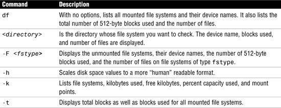
The following example illustrates how to display disk space information with the df command. Type the following:
df -k
The system responds with this:
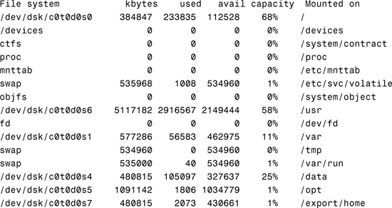
In this example, we used the -h option to output the information in a more readable format so that you can see the difference:
df -h
The system responds with this:
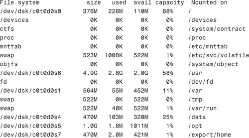
Notice that the -h option scales the values to a more readable format.
In both examples, you’ll see disk usage information displayed for each currently mounted file system.
You can also use the Solaris Management Console (SMC) Usage tool, which provides a graphical display of the available disk space for all mounted file systems. To use the Usage tool, follow the procedure outlined in Step by Step 1.14.
STEP BY STEP
1.14 Using the SMC Usage Tool
1. Launch the SMC by typing
smc&
2. In the left navigation window, select the This Computer icon from the left navigation pane, then select the Storage icon, and then click on the Mounts and Shares icon as shown in Figure 1.14.

A window will open, prompting you to enter the root password. The Mounts and Shares tools will be displayed as shown in Figure 1.15.

3. Select the Usage icon and the window shown in Figure 1.16 will be displayed.
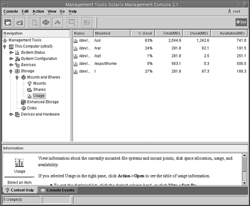
By using the df command, you display file system disk usage. You can use the du command to display the disk usage of a directory and all its subdirectories in 512-byte blocks. When used with the -h option, values are scaled to a more readable format.
The du command shows you the disk usage of each file in each subdirectory of a file system. To get a listing of the size of each subdirectory in a file system, type cd to the pathname associated with that file system and run the following pipeline:
du -s *| sort -r -n
This pipeline, which uses the reverse and numeric options of the sort command, pinpoints large directories. Use ls -l to examine the size (in bytes) and modification times of files within each directory. Old files or text files greater than 100KB often warrant storage offline.
The following example illustrates how to display the amount of disk space being consumed by the /var/adm directory using the du command. The largest files are displayed first, and the -k option displays the file size in 1024 bytes. Type the following:
du -k /var/adm|sort -r -n
The system responds with this:

In this example we use the -h option to output the information in a more readable format so that you can see the difference:
du -h /var/adm|sort -r -n
The system responds with this:

Note
The sort Command Notice that the files are not listed by file size. This is because the -n option to the sort command sorts data numerically, not by file size. The number 4 is a larger number, numerically, than the number 2. The -n option does not take into account that 4KB is smaller in size than 2.3MB.
The df command gives you capacity information on each mounted file system. The output of df and fsck is often misunderstood. This section goes into more detail about these two commands and describes their output so that you can better understand the information displayed. I begin with the fsck command. Remember, run fsck only on unmounted file systems, as shown in the following example. Type the following:
umount /mnt
fsck /dev/rdsk/c2t1d0s1
The system responds with this:
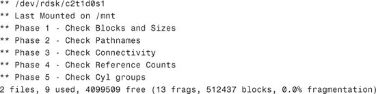
fsck first reports some things related to usage, as shown in Table 1.25.
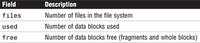
Note
Fragment Size A fragment is one data block in size, and a block consists of a number of data blocks, typically eight.
Then fsck reports more details of the free space, as shown in Table 1.26.
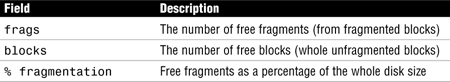
Fragmentation does not refer to fragmentation in the sense of a file’s disk blocks being inefficiently scattered across the whole file system, as you see in a Microsoft Windows file system.
In Solaris, a high percentage of fragmentation implies that much of the free space is tied up in fragments. In the previous example, fragmentation was 0%. High fragmentation affects creation of new files—especially those larger than a few data blocks. Typically, high fragmentation is caused by creating large numbers of small files.
Now let’s review the output from the df command:
mount /dev/dsk/c2t1d0s1 /mnt
df -k /mnt
The system responds with this:
![]()
The 4103598 value in the output represents the total file system size in kilobytes. It includes the 5% minfree that you specified earlier with the tunefs command. The output is summarized in Table 1.27.

Quotas let system administrators control the size of UFS file systems by limiting the amount of disk space that individual users can acquire. Quotas are especially useful on file systems where user home directories reside. After the quotas are in place, they can be changed to adjust the amount of disk space or number of inodes that users can consume. Additionally, quotas can be added or removed as system needs change. Also, quota status can be monitored. Quota commands enable administrators to display information about quotas on a file system or search for users who have exceeded their quotas.
After you have set up and turned on disk and inode quotas, you can check for users who exceed their quotas. You can also check quota information for entire file systems by using the commands listed in Table 1.28.
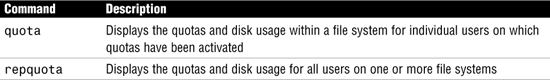
You won’t see quotas in use much today because the cost of disk space continues to fall. In most cases, the system administrator simply watches disk space to identify users who might be using more than their fair share. As you saw in this section, you can easily do this by using the du command. On a large system with many users, however, disk quotas can be an effective way to control disk space usage.
Another option for managing user space is the use of soft partitions described in Chapter 10. With soft partitions, each user’s home directory can be created within its own disk partition and would be limited to the space allocated to that partition.
Use the quot command to display how much disk space, in kilobytes, is being used by users. You do not need to implement disk quotas to use this command. The quot command can only be run by root. The syntax for the quot command is
quot -options <file system>
The quot command has two options:
![]()
To display disk space being used by all users on all mounted file systems, type the following:
quot -af
The system responds with the following output:
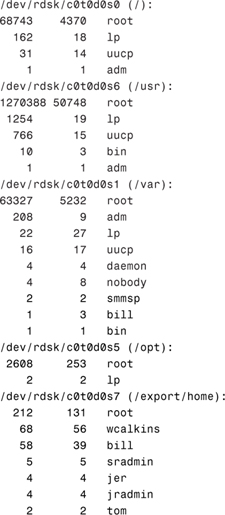
The columns of information displayed represent kilobytes used, number of files, and owner, respectively.
To display a count of the number of files and space owned by each user for a specific file system, enter
quot -f /dev/dsk/c0t0d0s7
The system responds with the following:

This concludes the discussion of file systems. This chapter discussed the various device drivers and device names used in Solaris 10. I described the Solaris commands and utilities used to obtain information about these devices and drivers. In addition to the devices that come standard with Solaris, this chapter also described Solaris Volume Manager and the added functionality it provides.
Device drivers are discussed in several chapters of this book because they are used in many aspects of the system administrator’s job. Devices are referenced when we install and boot the operating system (see Chapter 2, “Installing the Solaris 10 Operating Environment,” and Chapter 3, “System Startup and Shutdown”), when creating and mounting file systems, when setting up printers (see Chapter 6, “Managing the LP Print Service”), and in general troubleshooting of system problems. It is very important that you have a good understanding of how device drivers are configured and named in the Solaris operating system.
This chapter also introduced you to the many options available for constructing file systems using the mkfs and newfs commands. Other Solaris utilities for managing, labeling, copying, and tuning file systems were also presented.
The process of creating a file system on a disk partition was described. Many file system creation parameters that affect performance were presented. This chapter also detailed all the parts of a file system so that, as you create file systems, you are familiar with terminology you’ll encounter.
The mount and umount commands were described. In this chapter, I explained how to display mount options currently in use on a particular file system. In addition, the chapter showed you how to determine what process or user is using a file system before you unmount it.
In addition to showing how to manually mount file systems, this chapter described the Volume Manager for automatically mounting file systems on CD-ROM and disk. All the Volume Manager commands and associated configuration files were presented and explained.
Finally, the system administrator must monitor all file systems regularly. Commands and utilities used to monitor and manage file systems were described in detail.
Now that we’ve discussed devices, device and driver names, disk slices, and file systems, the next chapter will introduce the Solaris installation process.
![]() File system
File system minfree space
This exercise demonstrates three different methods that can be used to perform a reconfiguration boot so that the kernel recognizes new devices attached to the system.
Estimated time: 15 minutes
1. From the OpenBoot prompt, type the following:
boot -r
The system performs a reconfiguration boot and a login prompt appears.
2. Log in as root and create an empty file named /reconfigure as follows:
touch /reconfigure
Now reboot the system as follows:
/usr/sbin/shutdown -y -g0 -i6
The system performs a reconfiguration boot, and a login prompt appears.
3. Log in as root and issue the following command:
reboot -- -r
The system performs a reconfiguration boot, and a login prompt appears.
In this exercise, you’ll use a few of the Solaris commands to display information about devices connected to your system.
Estimated time: 5 minutes
1. Use the dmesg command to determine the mapping of an instance name to a physical device name. Type the following:
dmesg
In the output, identify the instance name assigned to each disk drive and peripheral attached to your system. On a system with IDE disks, you’ll see entries similar to the following:
sd0 is /pci@1f,0/pci@1,1/ide@3/sd@2,0
On a system with SCSI disks, you’ll see something like this:
sd17 is /pci@1f,0/pci@1/scsi@1,1/sd@1,0
2. Use the prtconf command to see which drivers are attached to the instance names identified in the previous step.
For example, you should see an entry something like this:
sd, instance #0
In this exercise, you’ll use the devfsadm command to add in a new device without rebooting the system.
Estimated time: 15 minutes
1. Connect a tape drive, disk drive, or CD-ROM to the system and perform a reconfiguration reboot.
2. Log in and issue the dmesg command to verify that the device has been installed. You should see an entry something like this if you’re adding an SCSI disk drive:
sd17 is /pci@1f,0/pci@1/scsi@1,1/sd@1,0
Check to see that a driver is attached by issuing the prtconf command.
3. Halt the system, turn off the new device, and boot the system back up using the boot command. Do not do a reconfiguration reboot.
4. Issue the prtconf command. It should display (driver not attached) next to the instance device name for that device.
5. Issue the devfsadm command.
6. Issue the prtconf command again. The message (driver not attached) next to the instance device name should be gone and the device is now available for use.
In this exercise, you determine the disk geometry and slice information of your disk drive.
Estimated time: 20 minutes
1. Log in as root.
2. Display and record your current disk configuration information using the prtvtoc command, as shown here:
prtvtoc <raw disk device name>
How are the disk slices arranged? What disk geometry does it display?
3. Now, follow these steps to look at your disk information using the format utility:
|
|
A. Type |
|
|
B. Type |
|
|
C. Type |
|
|
D. Type |
|
|
E. Press Ctrl+D. You’ll exit the |
The following exercise requires that you have a spare disk drive connected to your system or a spare, unused slice on a disk. You will practice creating a disk slice and creating a file system.
Estimated time: 30 minutes
1. Practice creating a slice on your spare disk drive using the steps outlined in the earlier section titled “Using the format Utility to Create Slices.”
2. Create a file system on the new or unused slice using the newfs command as follows:
newfs <raw device name>
3. Create a directory in the root partition named /test, as shown here:
mkdir /test
4. Mount the new file system to support large files using the following command:
mount -o largefiles <block device name> /test
5. Unmount the file system, as shown here:
umount /test
6. View the contents of the /etc/vfstab file on your system by typing cat /etc/vfstab.
7. Add the following line to the /etc/vfstab file for the file system you’ve just created so that it gets mounted automatically at boot time:
<block device name> <raw device> /test ufs 2 yes -
8. Reboot the system:
/usr/sbin/shutdown -y -g0 -i6
9. Verify that the file system was mounted automatically:
mount4p1
In this exercise, you’ll modify some of the file system parameters that were specified when the file system was originally created with the newfs command.
Estimated time: 15 minutes
1. Log in as root.
2. List all of the parameters currently in use on the file system by typing the following:
newfs -v <raw device name>
3. Open another window. Leave the information displayed in step 2 in the window for referencing later. In the new window, type the tunefs command to change the minfree value to 5% on the file system as follows:
tunefs -m5 <raw device name>
4. View the new file system parameters, but this time you’ll use the mkfs command as follows:
mkfs -m <raw device name>
Compare the parameters displayed with the parameters that were displayed earlier in the other window.
5. Try the fstyp command for viewing the file system parameters as follows:
fstyp -v <raw device name>
In this exercise, you’ll utilize Volume Manager to automatically mount a CD-ROM.
Estimated time: 10 minutes
1. Insert a CD-ROM into the CD-ROM player.
2. Type the mount command with no options to verify that the device was mounted. What is the mount point that was used?
3. Eject the CD-ROM as follows:
eject cdrom
4. Type the following command to look for the Volume Manager process named vold:
pgrep -l vold
5. Turn off the Volume Manager by typing the following:
/etc/init.d/volmgt stop
6. Type the following command to look for the Volume Manager process named vold:
pgrep -l vold
7. Insert the CD into the CD-ROM player. Did it mount the CD?
8. Restart the Volume Manager daemon by typing the following:
/etc/init.d/volmgt start
9. Type the mount command with no options to list all mounted file systems. Is the CD mounted now?