
Fast Facts
The Fast Facts listed in this chapter are designed as a refresher of key points, topics, and knowledge that are required to be successful on the Solaris System Administrator Certification exam. By using these summaries of key points, you can spend an hour prior to your exam to refresh your understanding of key topics and ensure that you have a solid understanding of the objectives and the information required for you to succeed in each major area of the exam.
This chapter is divided into two parts: Section 1 covers Exam CX-310-200, and Section 2 covers Exam CX-310-202. Therefore, you only need to study the section applicable to the exam you are preparing for. If you have a thorough understanding of the key points here, chances are good that you will pass the exam.
This chapter is designed as a quick study aid that you can use just prior to taking the exam. You should be able to review the Fast Facts for each exam in less than an hour. It cannot serve as a substitute for knowing the material supplied in these chapters. However, its key points should refresh your memory on critical topics. In addition to the information located in this chapter, remember to review the Glossary terms because they are intentionally not covered here.
Study these Fast Facts only when preparing for the Sun Certified System Administrator for the Solaris 10 Operating Environment—Part I exam (CX-310-200).
A file system is a structure of files and directories used to organize and store files on disks and other storage media. All disk-based computer systems have a file system. In Unix, file systems have two basic components: files and directories. A file is the actual information as it is stored on the disk, and a directory is a listing of the filenames. In addition to keeping track of filenames, the file system must also keep track of files’ access dates, permissions, and ownership.
A hard disk consists of several separate disk platters mounted on a common spindle. Data stored on each platter surface is written and read by disk heads. The circular path a disk head traces over a spinning disk platter is called a track.
Each track is made up of a number of sectors laid end to end. A sector consists of a header, a trailer, and 512 bytes of data. The header and trailer contain error-checking information to help ensure the accuracy of the data. Taken together, the set of tracks traced across all of the individual disk platter surfaces for a single position of the heads is called a cylinder.
In Solaris, each disk device is described in three ways, using three distinct naming conventions:
![]() Physical device name—Represents the full device pathname in the device information hierarchy.
Physical device name—Represents the full device pathname in the device information hierarchy.
![]() Instance name—Represents the kernel’s abbreviation name for every possible device on the system.
Instance name—Represents the kernel’s abbreviation name for every possible device on the system.
![]() Logical device name—Used by system administrators with most system commands to refer to devices.
Logical device name—Used by system administrators with most system commands to refer to devices.
The system commands used to provide information about physical devices are described in Table 1.

You can add new devices to a system without requiring a reboot if your system supports hot-plug devices. It’s all handled by the devfsadmd daemon that transparently builds the necessary configuration entries. Older commands such as drvconfig, disks, tapes, ports, and devlinks have been replaced by the devfsadm utility. The devfsadm command should now be used in place of all these commands; however, devfsadmd, the devfsadm daemon, automatically detects device configuration changes, so there should be no need to run this command interactively.
During the process of building the /devices directory, the devfsadmd daemon assigns each device a major device number by using the name-to-number mappings held in the /etc/name_to_major file. This file is maintained by the system. The major device number indicates the general device class, such as disk, tape, or serial line. The minor device number indicates the specific member within that class.
The /dev/dsk directory refers to the block or buffered device file, and the /dev/rdsk directory refers to the character or raw device file. The “r” in rdsk stands for “raw.”
The instance name represents the kernel’s abbreviated name for every possible device on the system. For example, on an Ultra system, dad0 represents the instance name of the IDE disk drive, and hme0 is the instance name for the network interface. Instance names are mapped to a physical device name in the /etc/path_to_inst file.
Following are the four types of disk-based file systems used by Solaris 10:
![]() UFS—The Unix file system, which is based on the BSD Fast file system (the traditional Unix file system). The UFS is the default disk-based file system used in Solaris.
UFS—The Unix file system, which is based on the BSD Fast file system (the traditional Unix file system). The UFS is the default disk-based file system used in Solaris.
![]() HSFS—The High Sierra and ISO 9660 file system. The HSFS is used on CD-ROMs and is a read-only file system.
HSFS—The High Sierra and ISO 9660 file system. The HSFS is used on CD-ROMs and is a read-only file system.
![]() PCFS—The PC file system, which allows read/write access to data and programs on DOS-formatted disks.
PCFS—The PC file system, which allows read/write access to data and programs on DOS-formatted disks.
![]() UDF (Universal Disk Format) file system—UDF is the industry-standard format for storing information on the optical media technology called DVD (Digital Versatile Disc).
UDF (Universal Disk Format) file system—UDF is the industry-standard format for storing information on the optical media technology called DVD (Digital Versatile Disc).
Virtual file systems, previously called pseudo file systems, are virtual or memory-based file systems that create duplicate paths to other disk-based file systems or provide access to special kernel information and facilities. Most virtual file systems do not use file system disk space, although a few exceptions exist. The following is a list of some of the more common types of virtual file systems:
![]() Cachefs—The cache file system.
Cachefs—The cache file system.
![]() TMPFS—The temporary file system uses local memory for file system reads and writes.
TMPFS—The temporary file system uses local memory for file system reads and writes.
![]()
/var/run—/var/run is the repository for temporary system files that are not needed across systems.
![]() MNTFS—The MNTFS type maintains information about currently mounted file systems.
MNTFS—The MNTFS type maintains information about currently mounted file systems.
![]() DEVFS—The DEVFS is used to manage the namespace of all devices on the system. This file system is used for the
DEVFS—The DEVFS is used to manage the namespace of all devices on the system. This file system is used for the /devices directory.
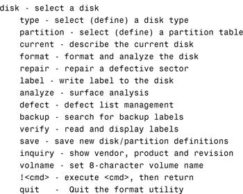
Disks are divided into regions called disk slices or disk partitions using the format utility or the Solaris Management Console. Make sure you understand all of the Format menu options and what tasks they perform. The following displays the main menu options in the format utility:
Here are the menu options available in the partition section of the format utility:
PARTITION MENU:

When you create a UFS, the disk slice is divided into cylinder groups. Disk configuration information is stored in the disk label. If you know the disk and slice number, you can display information for a disk by using the print volume table of contents (prtvtoc) command.
The slice is then divided into blocks to control and organize the structure of the files within the cylinder group. A UFS has the following four types of blocks. Each performs a specific function in the file system:
![]() Bootblock—Stores information used when booting the system
Bootblock—Stores information used when booting the system
![]() Superblock—Stores much of the information about the file system
Superblock—Stores much of the information about the file system
![]() Inode—Stores all information about a file except its name
Inode—Stores all information about a file except its name
![]() Storage or data block—Stores data for each file
Storage or data block—Stores data for each file
File systems can be mounted from the command line by using the mount command. The commands in Table 2 are used from the command line to mount and unmount file systems.

Common options used when mounting file systems are listed in Table 3.

Use the df command and its options to see the capacity of each file system mounted on a system, the amount of space available, and the percentage of space already in use. Use the du (directory usage) command to report the number of free disk blocks and files.
mkfs constructs a file system on the character (or raw) device found in the /dev/rdsk directory. Again, it is highly recommended that you do not run the mkfs command directly, but instead use the friendlier newfs command, which automatically determines all the necessary parameters required by mkfs to construct the file system.
The /etc/vfstab (virtual file system table) file contains a list of file systems to be automatically mounted when the system is booted to the multi-user state. Each column of information follows this format:
![]()
device to mount—The buffered device that corresponds to the file system being mounted.
![]()
device to fsck—The raw (character) special device that corresponds to the file system being mounted. This determines the raw interface used by fsck. Use a dash (-) when there is no applicable device, such as for swap, /proc, tmp, or a network-based file system.
![]()
mount point—The default mount point directory.
![]()
FS type—The type of file system.
![]()
fsck pass—The pass number used by fsck to decide whether to check a file. When the field contains a dash (-), the file system is not checked. When the field contains a value of 1 or greater, the file system is checked sequentially. File systems are checked sequentially in the order that they appear in the /etc/vfstab file. The value of the pass number has no effect on the sequence of file system checking.
![]()
mount at boot—Specifies whether the file system should be automatically mounted when the system is booted. The RC scripts located in the /etc directory specify which file system gets mounted at each run level.
![]() mount options—A list of comma-separated options (with no spaces) used when mounting the file system. Use a dash (
mount options—A list of comma-separated options (with no spaces) used when mounting the file system. Use a dash (-) to show no options.
Use the fsck command to repair file systems. fsck is a multipass file system check program that performs successive passes over each file system, checking blocks and sizes, pathnames, connectivity, reference counts, and the map of free blocks (possibly rebuilding it). fsck also performs file system cleanup.
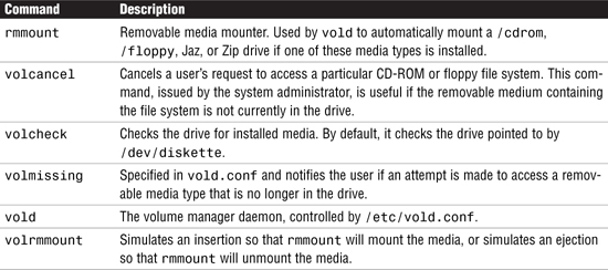
Volume management, with the vold daemon, is the mechanism that automatically mounts CD-ROMs and file systems when removable media containing recognizable file systems are inserted into the devices. The vold daemon is the workhorse behind volume manager. It is automatically started by the /etc/init.d/volmgt script. vold reads the /etc/vold.conf configuration file at startup. The vold.conf file contains the volume manager configuration information that vold uses.
Several other commands help you administer the volume manager on your system. They are described in Table 4.
File systems are checked and repaired with the fsck (file system check) command. fsck is a multipass file system check program that performs successive passes over each file system, checking blocks and sizes, pathnames, connectivity, reference counts, and the map of free blocks (possibly rebuilding it). fsck also performs cleanup.
The computer must meet the following requirements before you can install Solaris 10 using the interactive installation method:
![]() The system must have a minimum of 128MB of RAM (256MB is recommended). Sufficient memory requirements are determined by several factors, including the number of active users and applications you plan to run.
The system must have a minimum of 128MB of RAM (256MB is recommended). Sufficient memory requirements are determined by several factors, including the number of active users and applications you plan to run.
![]() The media is distributed on CD-ROM and DVD only, so a CD-ROM or DVD-ROM is required either locally or on the network. You can use all of the Solaris installation methods to install the system from a networked CD-ROM or DVD-ROM.
The media is distributed on CD-ROM and DVD only, so a CD-ROM or DVD-ROM is required either locally or on the network. You can use all of the Solaris installation methods to install the system from a networked CD-ROM or DVD-ROM.
![]() A minimum of 2GB of disk space is required. See the next section for disk space requirements for the specific Solaris software you plan to install. Also, remember to add disk space to support your environment’s swap space requirements.
A minimum of 2GB of disk space is required. See the next section for disk space requirements for the specific Solaris software you plan to install. Also, remember to add disk space to support your environment’s swap space requirements.
![]() When upgrading the operating system, you must have an empty 512MB slice on the disk. The swap slice is preferred, but you can use any slice that will not be used in the upgrade such as root (
When upgrading the operating system, you must have an empty 512MB slice on the disk. The swap slice is preferred, but you can use any slice that will not be used in the upgrade such as root (/), user, var, and opt.
![]() The system must be a SPARC (
The system must be a SPARC (sun4u or sun4m) or supported x86/x64-based system.
Be familiar with the following software terms:
![]() Software Package—A collection of files and directories in a defined format.
Software Package—A collection of files and directories in a defined format.
![]() Software Group—Software packages are grouped into software groups, which are logical collections of software packages. Sometimes these groups are referred to as clusters.
Software Group—Software packages are grouped into software groups, which are logical collections of software packages. Sometimes these groups are referred to as clusters.
For SPARC systems, software groups are grouped into six configuration groups to make the software installation process easier. These five configuration groups are reduced networking support, core system support, end-user support, developer system support, entire distribution, and entire distribution plus OEM system support.
You can use one of seven methods to install the Solaris software: interactive using a GUI, interactive using the command line, JumpStart, custom JumpStart, Flash Archive, WAN Boot, or Solaris Upgrade.
You have two upgrade options available. One upgrade option is available in the interactive installation if you are currently running Solaris 2.6, 7, 8, or 9 and you want to upgrade to Solaris 10. The other upgrade option is the Solaris Live upgrade, which enables an upgrade to be installed while the operating system is running and can significantly reduce the downtime associated with an upgrade. As described in Chapter 2, both upgrade options preserve most customizations you made in the previous version of Solaris.
During the installation, Solaris allocates disk space into separate file systems. By default, the interactive installation program (suninstall) sets up the root (/) and swap partitions. It’s typical to add additional file systems. The following is a typical partitioning scheme for a system with a single disk drive:
![]() root (
root (/) and /usr—Solaris normally creates two partitions for itself: root (/) and /usr. The installation program determines how much space you need. Most of the files in these two partitions are static. If the root (/) file system fills up, the system will not operate properly.
![]() swap—This area on the disk doesn’t have files in it. In Unix you’re allowed to have more programs running than will fit into the physical memory. The pieces that aren’t currently needed in memory are transferred into swap to free up physical memory for other active processes.
swap—This area on the disk doesn’t have files in it. In Unix you’re allowed to have more programs running than will fit into the physical memory. The pieces that aren’t currently needed in memory are transferred into swap to free up physical memory for other active processes.
![]()
/export/home—On a single-disk system, everything not in root (/), /usr, or swap should go into a separate partition. /export/home is where you would put user home directories and user-created files.
![]()
/var (optional)—Solaris uses this area for system log files, print spoolers, and email.
![]()
/opt (optional)—By default, the Solaris installation program loads optional software packages here. Also, third-party applications are usually loaded into /opt.
Solaris provides tools for adding and removing software from a system. Those tools are described in Table 5.

Another system administration task is managing system software patches. A patch is a fix to a reported software problem. Sun will ship several software patches to customers so that problems can be resolved before the next release of software. The existing software is derived from a specified package format that conforms to the ABI.
Patches are identified by unique alphanumeric strings. The patch base code comes first, then a hyphen, and then a number that represents the patch revision number. For example, patch 110453-01 is a Solaris patch to correct a known problem.
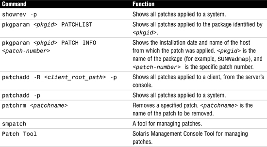
You might want to know more about patches that have previously been installed. Table 6 shows commands that provide useful information about patches already installed on a system.
During system startup, or bootup, the boot process goes through the following phases:
1. Boot PROM phase—After you turn on power to the system, the PROM displays system identification information and runs self-test diagnostics to verify the system’s hardware and memory. It then loads the primary boot program, called bootblk.
2. Boot program phase—The bootblk program finds and executes the secondary boot program (called ufsboot) from the UFS and loads it into memory. After the ufsboot program is loaded, it loads the two-part kernel.
3. Kernel initialization phase—The kernel initializes itself and begins loading modules, using ufsboot to read the files. When the kernel has loaded enough modules to mount the root file system, it unmaps the ufsboot program and continues, using its own resources.
4. init phase—The kernel starts the Unix operating system, mounts the necessary file systems, and runs /sbin/init to bring the system to the initdefault state specified in /etc/inittab.
The kernel creates a user process and starts the /sbin/init process, which starts other processes by reading the /etc/inittab file.
The /sbin/init process starts the run control (rc) scripts, which execute a series of other scripts. These scripts (/sbin/rc*) check and mount file systems, start various processes, and perform system maintenance tasks.
5. svc.startd phase—The svc.startd daemon starts the system services and boots the system to the appropriate milestone.
The hardware-level user interface that you see before the operating system starts is called the OpenBoot PROM (OBP). The primary tasks of the OpenBoot firmware are as follows:
![]() Test and initialize the system hardware.
Test and initialize the system hardware.
![]() Determine the hardware configuration.
Determine the hardware configuration.
![]() Start the operating system from either a mass storage device or a network.
Start the operating system from either a mass storage device or a network.
![]() Provide interactive debugging facilities for testing hardware and software.
Provide interactive debugging facilities for testing hardware and software.
![]() Allow modification and management of system startup configuration, such as NVRAM parameters.
Allow modification and management of system startup configuration, such as NVRAM parameters.
Specifically, the following tasks are necessary to initialize the operating system kernel:
1. OpenBoot displays system identification information and then runs self-test diagnostics to verify the system’s hardware and memory. These checks are known as a POST.
2. OpenBoot loads the primary startup program, bootblk, from the default startup device.
3. The bootblk program finds and executes the secondary startup program, ufsboot, and loads it into memory. The ufsboot program loads the operating system kernel.
A device tree is a series of node names separated by slashes (/). The top of the device tree is the root device node. Following the root device node, and separated by a leading slash (/), is a bus nexus node. Connected to a bus nexus node is a leaf node, which is typically a controller for the attached device. Each device pathname has this form:
driver-name@unit-address:device-arguments
Nodes are attached to a host computer through a hierarchy of interconnected buses on the device tree. OpenBoot deals directly with the hardware devices in the system. Each device has a unique name that represents both the type of device and the location of that device in the device tree. The OpenBoot firmware builds a device tree for all devices from information gathered at the POST. Sun uses the device tree to organize devices that are attached to the system.
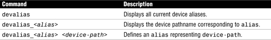
Device pathnames tend to get very long; therefore, the OpenBoot environment utilizes a method that allows you to assign shorter names to the long device pathnames. These shortened names are called device aliases and they are assigned using the devalias command. Table 7 describes the devalias command, which is used to examine, create, and change OpenBoot aliases.
When the kernel is loading, it reads the /etc/system file where system configuration information is stored. This file modifies the kernel’s parameters and treatment of loadable modules. It specifically controls the following:
![]() The search path for default modules to be loaded at boot time as well as the modules not to be loaded at boot time
The search path for default modules to be loaded at boot time as well as the modules not to be loaded at boot time
![]() The modules to be forcibly loaded at boot time rather than at first access
The modules to be forcibly loaded at boot time rather than at first access
![]() The new values to override the default kernel parameter values
The new values to override the default kernel parameter values
Various parameters are used to control the OpenBoot environment. Any user can view the OpenBoot configuration variables from a Unix prompt by typing the following:
/usr/sbin/eeprom
OpenBoot can be used to gather and display information about your system with the commands described in Table 8.

In addition, various hardware diagnostics can be run in OpenBoot to troubleshoot hardware and network problems.
The operating system is booted from the OpenBoot prompt using the boot command. You can supply several options to the OpenBoot boot command at the ok prompt. Table 9 describes each of these.

The following list describes the steps for booting interactively:
1. At the ok prompt, type boot -a and press Enter. The boot program prompts you interactively.
2. Press Enter to use the default kernel (/kernel/unix) as prompted, or type the name of the kernel to use for booting and press Enter.
3. Press Enter to use the default modules directory path as prompted, or type the path for the modules directory and press Enter.
4. Press Enter to use the default /etc/system file as prompted, or type the name of the system file and press Enter.
5. Press Enter to use the default root file system type as prompted (UFS for local disk booting, or NFS for diskless clients).
6. Press Enter to use the default physical name of the root device as prompted, or type the device name.
After the boot command initiates the kernel, the kernel begins several phases of the startup process. The first task is for OpenBoot to load the two-part kernel. The secondary startup program, ufsboot, which is described in the preceding section, loads the operating system kernel. The core of the kernel is two pieces of static code called genunix and unix. genunix is the platform-independent generic kernel file, and unix is the platform-specific kernel file. When the system boots, ufsboot combines these two files into memory to form the running kernel.
The kernel initializes itself and begins loading modules, using ufsboot to read the files. After the kernel has loaded enough modules to mount the root file system, it unmaps the ufsboot program and continues, using its own resources. The kernel creates a user process and starts the /sbin/init process.
During the init phase of the boot process, the init daemon (/sbin/init) reads the /etc/default/init file to set any environment variables. By default, only the TIMEZONE variable is set. Then, init reads the /etc/inittab file and executes any process entries that have sysinit in the action field, so that any special initializations can take place before users login.
After reading the /etc/inittab file, init starts the svc.startd daemon, which is responsible for starting and stopping other system services such as mounting file systems and configuring network devices. In addition, svc.startd will execute legacy run control (rc) scripts, which are described later in this section.
The kernel is dynamically configured in Solaris 10. The kernel consists of a small static core and many dynamically loadable kernel modules. Many kernel modules are loaded automatically at boot time, but for efficiency, others—such as device drivers—are loaded from the disk as needed by the kernel.
When the kernel is loading, it reads the /etc/system file where system configuration information is stored. This file modifies the kernel’s parameters and treatment of loadable modules.
After control of the system is passed to the kernel, the system begins initialization and starts the svc.startd daemon. In Solaris 10, the svc.startd daemon replaces the init process as the master process starter and restarter. Where in previous version of Solaris, init would start all processes and bring the system to the appropriate “run level” or “init state,” now SMF, or more specifically, the svc.startd daemon, assumes the role of starting system services.
The service instance is the fundamental unit of administration in the SMF framework and each SMF service has the potential to have multiple versions of it configured. An instance is a specific configuration of a service and multiple instances of the same version can run in the Solaris operating environment.
The services started by svc.startd are referred to as milestones. The milestone concept replaces the traditional run levels that were used in previous versions of Solaris. A milestone is a special type of service which represents a group of services. A milestone is made up of several SMF services. For example, the services which constituted run levels S, 2, and 3 in previous versions of Solaris are now represented by milestone services named.

Other milestones that are available in the Solaris 10 OE are

An SMF manifest is an XML (Extensible Markup Language) file that contains a complete set of properties that are associated with a service or a service instance. The properties are stored in files and subdirectories located in /var/svc/manifest.
The SMF provides a set of command-line utilities used to administer and configure the SMF that are described in Chapter 3.
A run level is a system state (run state), represented by a number or letter, that identifies the services and resources that are currently available to users. The who -r command can still be used to identify a systems run state as follows:
who -r
The system responds with the following, indicating that run-level 3 is the current run state:
![]()
Since the introduction of SMF in Solaris 10, we now refer to these run states as milestones and Chapter 3 describes how the legacy run states coincide with the Solaris 10 milestones.

Use the Solaris Management Console (SMC) GUI or the command line to create and manage user accounts.
Table 10 describes field entries you’ll need to know when setting up a new user account using SMC.

Another way to manage user accounts is from the command line. Although using the command line is more complex than using the SMC GUI, the command line provides a little more flexibility. Solaris supplies the user administration commands described in Table 11 for setting up and managing user accounts.

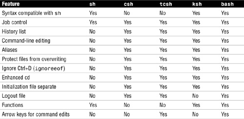
The Solaris 10 operating environment offers five commonly used shells:
![]() The Bourne shell (
The Bourne shell (/sbin/sh)—The default shell. It is a command programming language that executes commands read from a terminal or a file.
![]() The C shell (
The C shell (/bin/csh)—A command interpreter with a C-like syntax. The C-shell provides a number of convenient features for interactive use that are not available with the Bourne shell, including filename completion, command aliasing, and history substitution.
![]() The TENEX C shell (
The TENEX C shell (/bin/tcsh)—An enhanced version of the C shell with complete backward compatibility. The enhancements are mostly related to interactive use, including the ability to use arrow keys for command history retrieval and command-line editing.
![]() The Korn shell (
The Korn shell (/bin/ksh)—A command programming language that executes commands read from a terminal or a file.
![]() The Bourne Again shell (
The Bourne Again shell (/bin/bash)—Bash is a sh-compatible command language interpreter that executes commands read from the standard input or from a file. Bash also incorporates useful features from the Korn and C shells (ksh and csh).
The login shell is the command interpreter that runs when you log in. The Solaris 10 operating environment offers the three most commonly used shells, as described in Table 12.
The logout file functionality can be implemented with the use of a trap statement in /etc/profile:
![]()
A shell initialization file is a shell script that runs automatically each time the user logs in. The initialization file will set up the work environment and customize the shell environment for the user.
C shell initialization files run in a particular sequence after the user logs in to the system. For the C shell and tcsh, initialization files are run in the following sequence:
1. Commands in /etc/.login are executed.
2. Commands from the $HOME/.cshrc file (located in your home directory) are executed. In addition, each time you start a new shell or open a new window in CDE, commands from the $HOME/.cshrc are run. In tcsh, if $HOME/.tcshrc exists, it is used instead of $HOME/.cshrc.
3. The shell executes commands from the $HOME/.login file (located in your home directory). Typically, the $HOME/.login file contains commands to specify the terminal type and environment.
4. Finally, when startup processing is complete, the C shell begins reading commands from the default input device, the terminal.
5. When the shell terminates, it performs commands from the $HOME/.logout file (if it exists in your home directory).
Bourne shell initialization files run in a particular sequence after the user logs in to the system. For the Bourne shell, initialization files are run in the following sequence:
1. Commands in /etc/profile are executed.
2. Commands from the $HOME/.profile file (located in your home directory) are executed. Typically, the $HOME/.profile file contains commands to specify the terminal type and environment.
3. Finally, when startup processing is complete, the Bourne shell begins reading commands from the default input device, the terminal.
Korn shell initialization files run in a particular sequence after the user logs in to the system. For the Korn shell, initialization files are run in the following sequence:
1. Commands in /etc/profile are executed.
2. Commands from the $HOME/.profile file (located in your home directory) are executed. Typically, the $HOME/.profile file contains commands to specify the terminal type and environment.
3. If the environment variable $ENV is set to the name of a file and that file is present, commands located in this file are executed. In addition, this initialization file gets read (and the commands get executed) every time a new Korn shell is started after login.
4. Finally, when startup processing is complete, the Korn shell begins reading commands from the default input device, the terminal.
Bash initialization files run in a particular sequence after the user logs in to the system. For the Bash shell, initialization files are run in the following sequence:
1. Commands in /etc/profile are executed.
2. Commands in $HOME/.bash_profile are executed. This file serves the same purpose as $HOME/.profile in the Bourne and Korn shells.
3. Commands in $HOME/.bashrc are executed, but only if this is not a login shell.
4. When startup processing is complete, bash begins reading commands from the default input device, the terminal.
5. As a login session exits, $HOME/.bash_logout is processed.
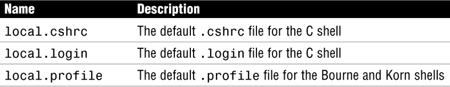
The Solaris 10 system software provides default user initialization files for each shell in the /etc/skel directory on each system. These files are listed in Table 13.
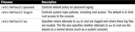
Protecting your system against unauthorized access or modification begins with controlling access to your system. Several files that control default system access are stored in the /etc/default directory. Table 14 summarizes the files in the /etc/default directory.
Controlling access to systems also involves using passwords and appropriate file permissions. Enforce the following guidelines on passwords:
![]() Passwords should contain a combination of six to eight letters, numbers, or special characters. Don’t use fewer than six characters.
Passwords should contain a combination of six to eight letters, numbers, or special characters. Don’t use fewer than six characters.
![]() Mix upper- and lowercase characters.
Mix upper- and lowercase characters.
![]() Use a password with nonalphabetic characters, such as numerals or punctuation.
Use a password with nonalphabetic characters, such as numerals or punctuation.
![]() Do not use words from a dictionary or easy-to-guess words.
Do not use words from a dictionary or easy-to-guess words.
Most of the user account information is stored in the /etc/passwd file; however, password encryption and password aging details are stored in the /etc/shadow file. Group information is stored in the /etc/group file.
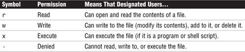
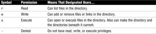
System security also involves protecting your data using standard Unix file permissions. File access permissions are shown by the ls -la command. The first column returned describes the type of file and its access permissions for the user, group, and others using letters. The r, w, and x are described in Table 15.
When listing the permissions on a directory, all columns of information are the same as for a file, with one exception. The r, w, and x found in the first column are treated slightly differently than for a file. These are described in Table 16.
Use the commands listed in Table 17 to modify file access permissions and ownership, but remember that only the owner of the file or root can assign or modify these values.

When a user creates a file or directory, the user mask controls the default file permissions assigned to the file or directory and is set using the umask command.
ACLs (pronounced ackls) can provide greater control over file permissions when the traditional Unix file protection in the Solaris operating system is not enough. An ACL provides better file security by enabling you to define file permissions for the owner, owner’s group, others, specific users and groups, and default permissions for each of these categories. The following are commands used to set and modify ACL entries:
![]()
setfacl—Set, modify, or delete ACL entries on a file
![]()
getfacl—Display or copy the ACL entry on a file
As the system administrator, you’ll need to monitor system resources and watch for unusual activity. Having a method to monitor the system is useful when you suspect a breach in security. The following commands are used to monitor users and system activity:

It is critical to turn off all unneeded network services because many of the services run by inetd, such as rexd, pose serious security threats. rexd is the daemon responsible for remote program execution. On a system connected to the rest of the world via the Internet or other public network, this could create a potential entry point for a hacker. TFTP should absolutely be disabled if you don’t have diskless clients using it. Most sites will also disable Finger so that external users can’t figure out the usernames of your internal users. Everything else depends on the needs of your site.
Solaris 10’s File Transfer Protocol (FTP) is a common tool for transferring files across the network. Although most sites leave FTP enabled, you need to limit who can use it. Solaris 10 contains a file named /etc/ftpd/ftpusers that is used to restrict access via FTP. The /etc/ftpd/ftpusers file contains a list of login names that are prohibited from running an FTP login on the system.
The /etc/hosts.equiv file contains a list of trusted hosts for a remote system and can present a potential security risk. When an entry for a host is made in /etc/hosts.equiv, such as the sample entry for system1, this means that the host is trusted and so is any user at that machine. If the username is also mentioned, as in the second entry in the same file, the host is trusted only if the specified user is attempting access. A single line of + in the /etc/hosts.equiv file indicates that every known host is trusted—this should never be used.
The $HOME/.rhosts file is the user equivalent of the /etc/hosts.equiv file, except any user can create an $HOME/.rhosts file granting access to whomever the user chooses—without the system administrator’s knowledge. The system administrator should disallow the use of .rhosts files—or even better, disable all R services.
It is recommended that you use the secure shell (ssh) when establishing communication between two hosts over insecure networks such as the Internet. The secure shell is much safer than previous methods used to access remote systems such as rlogin, rsh, and rcp. The secure shell daemon (sshd) listens for connections and handles the encrypted authentication exchange between two hosts. When authentication is complete, the user can execute commands and copy files remotely and securely.
Root access needs to be safeguarded against unauthorized use. You should assume that any intruder is looking for root access. You can protect the superuser account on a system by restricting access to a specific device through the /etc/default/login file. In the /etc/default/login file, you can control where root is able to log in by assigning one of the following values to the variable named CONSOLE:
![]()
Users can still log in using a non-root login and issue the su command to switch from being a user to being root, but this activity is logged in the file /var/adm/sulog. The sulog file lists all uses of the su command—not only those used to switch from being a user to being superuser.
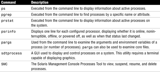
A process is distinct from a job or command, which can be composed of many processes working together to perform a specific task. Each process has a process ID associated with it and is referred to as a pid. You can monitor processes that are currently executing by using one of the commands listed in Table 18.
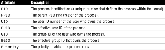
A process has certain attributes that directly affect execution. These are listed in Table 19.
The kill command sends a terminate signal (signal 15) to the process, and the process is terminated. Signal 15, which is the default when no options are used with the kill command, is a gentle kill that allows a process to perform cleanup work before terminating. Signal 9, on the other hand, is called a sure, unconditional kill because it cannot be caught or ignored by a process. If the process is still around after a kill -9, it is either hung up in the Unix kernel, waiting for an event such as disk I/O to complete, or you are not the owner of the process.
Another way to kill a process is to use the pkill command. A signal name or number may be specified as the first command-line option to pkill. For example, to kill the process named psef, issue the following command:
pkill -9 psef
A way to divide processes on a busy system is to schedule jobs so that they run at different times. A large job, for example, could be scheduled to run at 2 a.m., when the system would normally be idle. Solaris supports three methods of batch processing: the crontab command, at command, and SMC Job Scheduler tool. The crontab command schedules multiple system events at regular intervals, and the at command schedules a single system event for execution at a later time.
The cron daemon handles the automatic scheduling of crontab commands. Its function is to check the /var/spool/cron/crontab directory every 15 minutes for the presence of crontab files. It checks for new crontab files or changes to existing ones, reads the execution times listed within the files, and submits the commands for execution at the proper times.
Table 20 describes the fields in the crontab file for scheduling jobs to run on a regular basis.

Control who can access the crontab by configuring /etc/cron.d/cron.deny and /etc/cron.d/cron.allow. These access control files work together in the following manner:
![]() If
If cron.allow exists, only the users listed in this file can create, edit, display, and remove crontab files.
![]() If
If cron.allow doesn’t exist, all users may submit crontab files, except for users listed in cron.deny.
![]() If neither
If neither cron.allow nor cron.deny exists, superuser privileges are required to run crontab.
The Solaris Management Console (SMC) includes a graphical tool to create and schedule cron jobs on your system. You can use the Job Scheduler Tool to
![]() View and modify job properties.
View and modify job properties.
![]() Delete a job.
Delete a job.
![]() Add a scheduled job.
Add a scheduled job.
![]() Enable or disable job logging.
Enable or disable job logging.
The Job Scheduler tool is really just a GUI for managing crontab entries.
Projects and tasks are used to identify what is called a workload. For projects, this means some related work, such as payroll development. For tasks, it means a group of processes that represent a component of a workload, such as calculation of pay.
The concept behind projects is to be able to identify the separate workloads that are running on the system, and then to administer and report on them individually. Projects are useful when using a chargeback method to “bill” each project for resource usage. This allows the extended accounting software to identify how much resource a particular project has used.
A user or group can belong to one or more projects and also can be assigned a default project, very similar to the standard Solaris group membership mechanism. Project administration is carried out using the file /etc/project.
Table 21 lists a number of commands that are used to administer projects and tasks.

Many methods can be used to define a printer on a Solaris system. The following tools are available in Solaris 10 to set up and administer printers:
![]() Solaris Print Manager—A GUI that provides the ability to configure and manage printers.
Solaris Print Manager—A GUI that provides the ability to configure and manage printers.
![]() LP print service commands—The various LP commands available from the command line to configure and manage printers.
LP print service commands—The various LP commands available from the command line to configure and manage printers.
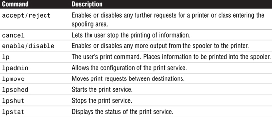
Although the GUI is an easy tool to use, the LP commands used from the command line offer more functionality. Table 22 lists the lp commands, which are the command-line means for controlling printers and print queues.
There are three types of printer configurations that you need to understand:
![]() Local printer—A printer physically connected to a system and accessed from that local system.
Local printer—A printer physically connected to a system and accessed from that local system.
![]() Network printer—A printer physically attached to the network with its own hostname and IP address. A network printer provides print services to clients, but is not directly connected to a print server.
Network printer—A printer physically attached to the network with its own hostname and IP address. A network printer provides print services to clients, but is not directly connected to a print server.
![]() Remote printer—A printer that users access over the network. This printer is either physically attached to a remote system or is physically attached to the network.
Remote printer—A printer that users access over the network. This printer is either physically attached to a remote system or is physically attached to the network.
A print server is a system that has a local printer connected to it and makes the printer available to other systems on the network. A print client is a remote system that can send print requests to a print server. A system becomes a print client when you install the print client software and enable access to remote printers on the system. Any networked Solaris system with a printer can be a print server, as long as the system has adequate resources to manage the printing load.
The /usr/lib/lpsched, also referred to as the scheduler daemon, is the Unix utility that is responsible for scheduling and printing in Solaris 10. Sometimes it is referred to as the lp daemon. The lpsched print daemon takes output from the spooling directory and sends it to the correct printer. lpsched also tracks the status of printers and filters on the print server.
The /usr/sbin/inetd daemon is started at bootup, and it listens for service requests on all the ports associated with each of the services listed in its configuration file. When inetd receives a print request, in.lpd is started to service the connection. The in.lpd daemon exits after the request has been serviced.
The Solaris LP print service performs the following functions:
![]() Initialization—Initializes a printer prior to sending it a print request to ensure that the printer is in a known state.
Initialization—Initializes a printer prior to sending it a print request to ensure that the printer is in a known state.
![]() Queuing—Schedules the print requests that are waiting to be sent to the printer.
Queuing—Schedules the print requests that are waiting to be sent to the printer.
![]() Tracking—Tracks the status of every print request. It enables the system administrator to manage all of the requests and allows users to view or cancel their own requests. It also logs errors that may have occurred during the printing process.
Tracking—Tracks the status of every print request. It enables the system administrator to manage all of the requests and allows users to view or cancel their own requests. It also logs errors that may have occurred during the printing process.
![]() Fault notification—This function prints the error message on the console or sends the message via email to the user.
Fault notification—This function prints the error message on the console or sends the message via email to the user.
![]() Filtering—Converts the print jobs to the appropriate type of file for the destination printer.
Filtering—Converts the print jobs to the appropriate type of file for the destination printer.
Most of the lp configuration files are located in the /var/spool/lp directory, except for the interface files, which are located in the /etc/lp/interfaces directory. A SCHEDLOCK file should be in /var/spool/lp; it is responsible for ensuring that only one instance of lpsched runs. You use the lpadmin command to add, configure, and delete printers from the system.
You can put several locally attached printers into a group called a printer class. When you have set up a printer class, users can then specify the class (rather than individual printers) as the destination for a print request. The first printer in the class that is free to print is used. You create printer classes with the lpadmin command as follows:
lpadmin -p <printer-name> -c <printer-class>
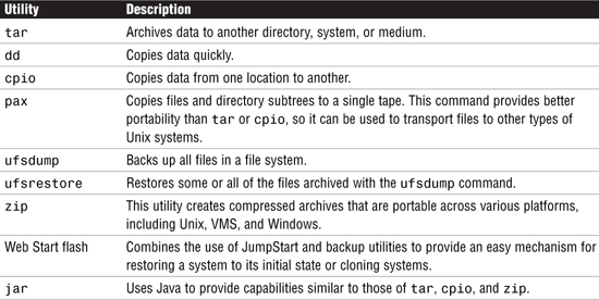
Solaris provides the utilities listed in Table 23. They can be used to back up data from disk to removable media and restore it.
You can use the fssnap command to create a read-only snapshot of a file system while the file system is mounted. A snapshot is a point-in-time image of a file system that provides a stable and unchanging device interface for backups. Unlike ufsdump, a UFS snapshot enables you to keep the file system mounted and the system in multiuser mode during backups. The snapshot is stored to disk, and then you can use Solaris backup commands like ufsdump, tar, and cpio to back up the UFS snapshot.
Create the snapshot using the fssnap command as follows:
fssnap -F ufs -o bs=/var/tmp /export/home
Another way to back up your Solaris operating environment (not the data) is to create a Web Start archive. The Web Start flash archive feature can be used to back up your Solaris operating environment or to replicate an installation on a number of systems, called clone systems. While in single-user mode, you can use the flarcreate command to create the Web Start archive.
Study these fast facts only when preparing for the Sun Certified System Administrator for the Solaris 10 Operating Environment—Part II exam (CX-310-202).
In the ISO/OSI model, services that are required for communication are arranged in seven layers that build on one another. Think of the layers as steps that must be completed before you can move on to the next step and ultimately communicate between systems. Table 24 describes the function of each individual layer.

Following are some network definitions and descriptions of networking hardware components:
![]() Packet—A packet is the unit of data to be transferred over the network, typically 1500 bytes for Ethernet.
Packet—A packet is the unit of data to be transferred over the network, typically 1500 bytes for Ethernet.
![]() Ethernet—Ethernet is a set of standards that define the physical components and protocol that a machine uses to access the network, and the speed at which the network runs. It includes specifications for cabling, connectors, and computer interface components. Furthermore, the Ethernet standards include data link layer protocols that run on Ethernet hardware.
Ethernet—Ethernet is a set of standards that define the physical components and protocol that a machine uses to access the network, and the speed at which the network runs. It includes specifications for cabling, connectors, and computer interface components. Furthermore, the Ethernet standards include data link layer protocols that run on Ethernet hardware.
![]() NIC—The computer hardware that lets you connect the computer to a network is known as a Network Interface Card (NIC) or network adapter. Most computers nowadays come with a NIC already installed.
NIC—The computer hardware that lets you connect the computer to a network is known as a Network Interface Card (NIC) or network adapter. Most computers nowadays come with a NIC already installed.
![]() Host—If you are an experienced Solaris user, you are no doubt familiar with the term host, often used as a synonym for computer or machine. From a TCP/IP perspective, only two types of entities exist on a network: routers and hosts.
Host—If you are an experienced Solaris user, you are no doubt familiar with the term host, often used as a synonym for computer or machine. From a TCP/IP perspective, only two types of entities exist on a network: routers and hosts.
![]() Switch—A multiport device that connects a number of systems on a network. Unlike the hub, the switch reduces network collisions by only sending packets to the intended destination, instead of sending them to all connected systems. Switches are now used more commonly than hubs.
Switch—A multiport device that connects a number of systems on a network. Unlike the hub, the switch reduces network collisions by only sending packets to the intended destination, instead of sending them to all connected systems. Switches are now used more commonly than hubs.
![]() Hubs and cabling—Ethernet cabling is run to each system from a hub or switch. The hub does nothing more than connect all the Ethernet cables so that the computers can connect to one another. It does not boost the signal or route packets from one network to another.
Hubs and cabling—Ethernet cabling is run to each system from a hub or switch. The hub does nothing more than connect all the Ethernet cables so that the computers can connect to one another. It does not boost the signal or route packets from one network to another.
![]() Router—A router is a machine that forwards packets from one network to another. In other words, the router connects networks, and the hub connects hosts.
Router—A router is a machine that forwards packets from one network to another. In other words, the router connects networks, and the hub connects hosts.
There are five classes of IP addresses: A, B, C, D, and E. The following is a brief description of each class.
Class A networks are used for large networks with millions of hosts, such as large multinational businesses with offices around the world. A class A network number uses the first 8 bits of the IP address as its network ID. The remaining 24 bits comprise the host part of the IP address. The values assigned to the first byte of class A network numbers fall within the range 0–127. For example, consider the IP address 75.4.10.4. The value 75 in the first byte indicates that the host is on a class A network. The remaining bytes, 4.10.4, establish the host address. The Internet registries assign only the first byte of a class A number. Use of the remaining three bytes is left to the discretion of the owner of the network number. Only 127 class A networks can exist; each of these networks can accommodate up to 16,777,214 hosts.
Class B networks are medium-sized networks, such as universities and large businesses with many hosts. A class B network number uses 16 bits for the network number and 16 bits for host numbers. The first byte of a class B network number is in the range 128–191. In the number 129.144.50.56, the first two bytes, 129.144, are assigned by the Internet registries and comprise the network address. The last two bytes, 50.56, make up the host address and are assigned at the discretion of the network’s owner. A class B network can accommodate a maximum of 65,534 hosts.
Class C networks are used for small networks containing fewer than 254 hosts. Class C network numbers use 24 bits for the network number and 8 bits for host numbers. A class C network number occupies the first three bytes of an IP address; only the fourth byte is assigned at the discretion of the network’s owner. The first byte of a class C network number covers the range 192–223. The second and third bytes each cover the range 0–255. A typical class C address might be 192.5.2.5, with the first three bytes, 192.5.2, forming the network number. The final byte in this example, 5, is the host number. A class C network can accommodate a maximum of 254 hosts.
Class D addresses cover the range 224–239 and are used for IP multicasting as defined in RFC 988. Class E addresses cover the range 240–255 and are reserved for experimental use.
CIDR, also called supernetting, uses (typically) the first 18 bits of an IPv4 address as the network portion, leaving 14 bits to be used for the host. This implementation has meant that networks can be aggregated by routers for ease of delivery, in the same way as the telephone system uses area codes to route telephone calls. The Internet now operates in a classless mode, and has greatly increased the number of IPv4 addresses that are available. There will not be any questions in the exam on CIDR. This is included for information only.
You can configure additional interfaces at system boot or modify the original interface by having an understanding of only three files: /etc/hostname.<interface>, /etc/inet/hosts, and /etc/inet/ipnodes.
This file defines the network interfaces on the local host. At least one /etc/hostname.<interface> file should exist on the local machine. The Solaris installation program creates this file for you. In the filename, <interface> is replaced by the device name of the primary network interface.
The file contains only one entry: the hostname or IP address associated with the network interface. For example, suppose hme0 is the primary network interface for a machine called system1. The file would be called /etc/hostname.hme0, and the file would contain the entry system1. An entry for system1 should also exist in the /etc/inet/hosts file.
The hosts database contains details of the machines on your network. This file contains the hostnames and IPv4 addresses of the primary network interface and any other network addresses the machine must know about. When a user enters a command such as ping xena, the system needs to know how to get to the host named xena. The /etc/inet/hosts file provides a cross-reference to look up and find xena’s network IP address. For compatibility with BSD-based operating systems, the file /etc/hosts is a symbolic link to /etc/inet/hosts.
Each line in the /etc/inet/hosts file uses the following format:
<address> <hostname> [nickname] [#comment]

The ipnodes database also contains details of the machines on your network. This file contains the hostnames and IPv4 or IPv6 addresses of the primary network interface and any other network addresses the machine must know about. You should note that, unlike the /etc/hosts file, which is a link to /etc/inet/hosts, there is no /etc/ipnodes link. The syntax for the ipnodes file is the same as the hosts file.
To manually change the hostname of a system, modify the following four files and reboot:
![]()
/etc/nodename—This file contains the official name when referring to a system; this is the hostname of the system.
![]()
/etc/hostname.<interface>—This file defines the network interfaces on the local host.
![]()
/etc/inet/hosts—The hosts file contains details of the machines on your network. This file contains only the IPv4 address for a host.
![]()
/etc/inet/ipnodes—This file is similar to the hosts file, but contains IPv6 or IPv4 addresses for hosts. It is automatically populated when the Operating Environment is installed and any changes to the /etc/inet/hosts file should be replicated here.
You can also use the sys-unconfig command to change the system hostname. This method actually requires you to re-enter most of the system identification that was entered when the Solaris Operating Environment was initially installed. When you run sys-unconfig, the system automatically shuts down. When it is next started, you are prompted to enter the information for IP address, hostname, network mask, time zone, name service, and the root password.
Physical memory is supplemented by specially configured space on the physical disk known as swap. Swap is configured either on a special disk partition known as a swap partition or on a swap file system. In addition to swap partitions, special files called swap files can also be configured in existing UFSs to provide additional swap space when needed. The Solaris virtual memory system provides transparent access to physical memory, swap, and memory-mapped objects.
The swap command is used to add, delete, and monitor swap files. The options for swap are shown in Table 26.

The Solaris installation program automatically allocates 512 Megabytes of swap if a specific value is not specified.
Core files are created when a program, or application, terminates abnormally. The default location for a core file to be written is the current working directory.
Core files are managed using the coreadm command. When entered with no options, coreadm displays the current configuration, as specified by /etc/coreadm.conf. The options are shown in Table 27.

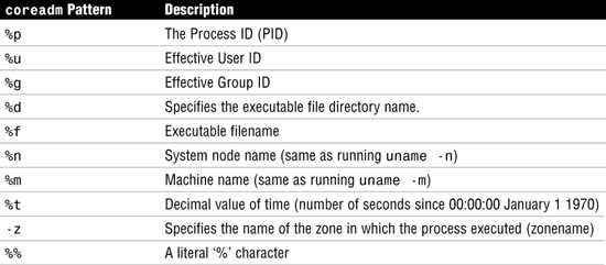
Core file names can be customized using a number of embedded variables. Table 28 lists the possible patterns:
A crash dump is a snapshot of the kernel memory, saved on disk, at the time a fatal system error occurred. When a serious error is encountered, the system displays an error message on the console, dumps the contents of kernel memory by default, and then reboots the system.
Normally, crash dumps are configured to use the swap partition to write the contents of memory. The savecore program runs when the system reboots and saves the image in a predefined location, usually /var/crash/<hostname> where <hostname> represents the name of your system.
Configuration of crash dump files is carried out with the dumpadm command. Running this command with no options will display the current configuration by reading the file /etc/dumpadm.conf.
dumpadm options are shown in Table 29.

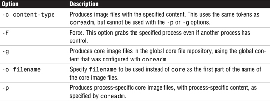
The gcore command can be used to create a core image of a specified running process. By default, the resulting file will be named core.<pid>, where <pid> is the pid of the running process.
The NFS service allows computers of different architectures, running different operating systems, to share file systems across a network. Just as the mount command lets you mount a file system on a local disk, NFS lets you mount a file system that is located on another system anywhere on the network. The NFS service provides the following benefits:
![]() Lets multiple computers use the same files so that everyone on the network can access the same data. This eliminates the need to have redundant data on several systems.
Lets multiple computers use the same files so that everyone on the network can access the same data. This eliminates the need to have redundant data on several systems.
![]() Reduces storage costs by having computers share applications and data.
Reduces storage costs by having computers share applications and data.
![]() Provides data consistency and reliability because all users can read the same set of files.
Provides data consistency and reliability because all users can read the same set of files.
![]() Makes mounting of file systems transparent to users.
Makes mounting of file systems transparent to users.
![]() Makes accessing remote files transparent to users.
Makes accessing remote files transparent to users.
![]() Supports heterogeneous environments.
Supports heterogeneous environments.
![]() Reduces system administration overhead.
Reduces system administration overhead.
Solaris 10 introduced NFS version 4, which has the following features:
![]() The UID and GID are represented as strings, and a new daemon,
The UID and GID are represented as strings, and a new daemon, nfs4mapid, provides the mapping to numeric IDs.
![]() The default transport for NFS version 4 is the Remote Direct Memory Access (RDMA) protocol, a technology for memory-to-memory transfer over high speed data networks.
The default transport for NFS version 4 is the Remote Direct Memory Access (RDMA) protocol, a technology for memory-to-memory transfer over high speed data networks.
![]() All state and lock information is destroyed when a file system is unshared. In previous versions of NFS, this information was retained.
All state and lock information is destroyed when a file system is unshared. In previous versions of NFS, this information was retained.
![]() NFS4 provides a pseudo file system to give clients access to exported objects on the NFS server.
NFS4 provides a pseudo file system to give clients access to exported objects on the NFS server.
![]() NFS4 is a stateful protocol where both the client and server hold information about current locks and open files. When a failure occurs, the two work together to re-establish the open, or locked files.
NFS4 is a stateful protocol where both the client and server hold information about current locks and open files. When a failure occurs, the two work together to re-establish the open, or locked files.
![]() NFS4 no longer uses the
NFS4 no longer uses the mountd, statd, or nfslogd daemons.
![]() NFS4 supports delegation, which allows the management responsibility of a file to be delegated to the client. Both the server and client support delegation. A client can be granted a read delegation, which can be granted to multiple clients, or a write delegation, providing exclusive access to a file.
NFS4 supports delegation, which allows the management responsibility of a file to be delegated to the client. Both the server and client support delegation. A client can be granted a read delegation, which can be granted to multiple clients, or a write delegation, providing exclusive access to a file.
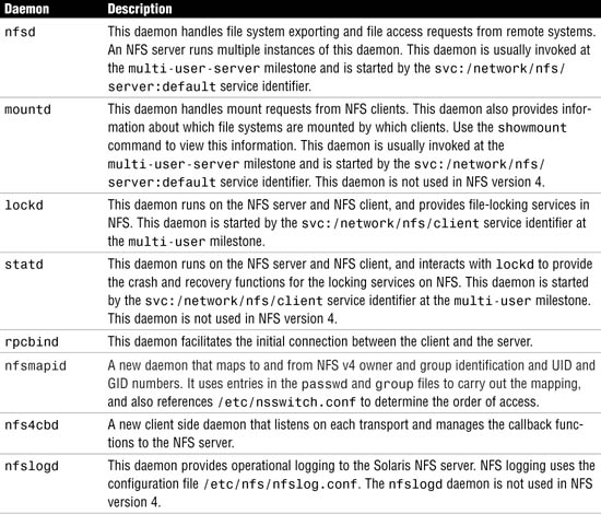
NFS uses a number of daemons to handle its services. These services are initialized at startup from the svc:/network/nfs/server:default and svc:/network/nfs/client:default startup service management functions. The most important NFS daemons are outlined in Table 31.
When a network contains even a moderate number of systems, all trying to mount file systems from each other, managing NFS can quickly become a nightmare. The Autofs facility, also called the automounter, is designed to handle such situations by providing a method in which remote directories are mounted only when they are being used.
When a request is made to access a file system at an Autofs mount point, the system goes through the following steps:
1. Autofs intercepts the request.
2. Autofs sends a message to the automountd daemon for the requested file system to be mounted.
3. automountd locates the file system information in a map and performs the mount.
4. Autofs allows the intercepted request to proceed.
5. Autofs unmounts the file system after a period of inactivity.
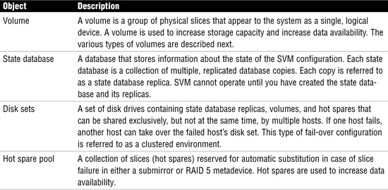
Solaris Volume Manager (SVM), formally called Solstice DiskSuite, comes bundled with the Solaris 10 operating system and uses virtual disks, called volumes, to manage physical disks and their associated data. A volume is functionally identical to a physical disk in the view of an application. You may also hear volumes referred to as virtual or pseudo devices. SVM uses metadevice objects, of which there are four main types: metadevices, state database replicas, disk sets, and hot spare pools. These are described in Table 32.
The types of SVM volumes you can create using Solaris Management Console or the SVM command-line utilities are concatenations, stripes, concatenated stripes, mirrors, and RAID5 volumes. SVM volumes can be any of the following:
![]() Concatenation—Concatenations work much the way the Unix
Concatenation—Concatenations work much the way the Unix cat command is used to concatenate two or more files to create one larger file. If partitions are concatenated, the addressing of the component blocks is done on the components sequentially, which means that data is written to the first available stripe until it is full, then moves to the next available stripe. The file system can use the entire concatenation, even though it spreads across multiple disk drives. This type of volume provides no data redundancy and the entire volume fails if a single slice fails.
![]() Stripe—A stripe is similar to a concatenation, except that the addressing of the component blocks is interlaced on the slices rather than sequentially. In other words, all disks are accessed at the same time in parallel. Striping is used to gain performance. When data is striped across disks, multiple disk heads and possibly multiple controllers can access data simultaneously. Interlace refers to the size of the logical data chunks on a stripe. Different interlace values can increase performance.
Stripe—A stripe is similar to a concatenation, except that the addressing of the component blocks is interlaced on the slices rather than sequentially. In other words, all disks are accessed at the same time in parallel. Striping is used to gain performance. When data is striped across disks, multiple disk heads and possibly multiple controllers can access data simultaneously. Interlace refers to the size of the logical data chunks on a stripe. Different interlace values can increase performance.
![]() Concatenated stripe—A concatenated stripe is a stripe that has been expanded by concatenating additional striped slices.
Concatenated stripe—A concatenated stripe is a stripe that has been expanded by concatenating additional striped slices.
![]() Mirror—A mirror is composed of one or more stripes or concatenations. The volumes that are mirrored are called submirrors. SVM makes duplicate copies of the data located on multiple physical disks, and presents one virtual disk to the application. All disk writes are duplicated; disk reads come from one of the underlying submirrors. A mirror replicates all writes to a single logical device (the mirror) and then to multiple devices (the submirrors) while distributing read operations. This provides redundancy of data in the event of a disk or hardware failure.
Mirror—A mirror is composed of one or more stripes or concatenations. The volumes that are mirrored are called submirrors. SVM makes duplicate copies of the data located on multiple physical disks, and presents one virtual disk to the application. All disk writes are duplicated; disk reads come from one of the underlying submirrors. A mirror replicates all writes to a single logical device (the mirror) and then to multiple devices (the submirrors) while distributing read operations. This provides redundancy of data in the event of a disk or hardware failure.
![]() RAID 5—Stripes the data across multiple disks to achieve better performance. In addition to striping, RAID 5 replicates data by using parity information. In the case of missing data, the data can be regenerated using available data and the parity information. A RAID 5 metadevice is composed of multiple slices. Some space is allocated to parity information and is distributed across all slices in the RAID5 metadevice. The striped metadevice performance is better than the RAID 5 metadevice, but it doesn’t provide data protection (redundancy).
RAID 5—Stripes the data across multiple disks to achieve better performance. In addition to striping, RAID 5 replicates data by using parity information. In the case of missing data, the data can be regenerated using available data and the parity information. A RAID 5 metadevice is composed of multiple slices. Some space is allocated to parity information and is distributed across all slices in the RAID5 metadevice. The striped metadevice performance is better than the RAID 5 metadevice, but it doesn’t provide data protection (redundancy).
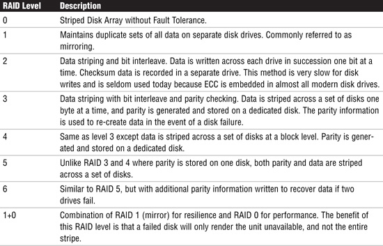
When describing SVM volumes, it’s common to describe which level of RAID the volume conforms to. Usually these disks are housed together in a cabinet and referred to as an array. There are several RAID levels, each referring to a method of distributing data while ensuring data redundancy. These levels are not ratings, but rather classifications of functionality. Different RAID levels offer dramatic differences in performance, data availability, and data integrity depending on the specific I/O environment. Table 33 describes the various levels of RAID.
The SVM state database contains vital information on the configuration and status of all volumes, hot spares, and disk sets. There are normally multiple copies of the state database, called replicas, and it is recommended that state database replicas be located on different physical disks, or even controllers if possible, to provide added resilience.
The state database, together with its replicas, guarantees the integrity of the state database by using a majority consensus algorithm.
The state database is created and managed using the metadb command. Table 34 shows the metadb options.

Role-Based Access Control (RBAC) and system logging are related in that they are involved in the securing and monitoring of systems in a Solaris environment.
With role-based access control (RBAC) in the Solaris 10 operating environment, administrators can assign limited administrative capabilities to non-root users. This is achieved through three features:
![]() Authorizations—User rights that grant access to a restricted function
Authorizations—User rights that grant access to a restricted function
![]() Execution profiles—Bundling mechanisms for grouping authorizations and commands with special attributes; for example, user and group IDs or superuser ID
Execution profiles—Bundling mechanisms for grouping authorizations and commands with special attributes; for example, user and group IDs or superuser ID
![]() Roles—Special types of user accounts intended for performing a set of administrative tasks
Roles—Special types of user accounts intended for performing a set of administrative tasks
RBAC relies on the following four databases to provide users access to privileged operations:
![]()
user_attr (extended user attributes database)—Associates users and roles with authorizations and profiles
![]()
auth_attr (authorization attributes database)—Defines authorizations and their attributes and identifies the associated help file
![]()
prof_attr (rights profile attributes database)—Defines profiles, lists the profile’s assigned authorizations, and identifies the associated help file
![]()
exec_attr (profile attributes database)—Defines the privileged operations assigned to a profile
The information handled by a name service includes the following:
![]() System (host) names and addresses
System (host) names and addresses
![]() Usernames
Usernames
![]() Passwords
Passwords
![]() Access permissions
Access permissions
Table 35 describes the name services available in Solaris 10.

/etc files are the traditional Unix way of maintaining information about hosts, users, passwords, groups, and automount maps, to name just a few. These files are text files located on each individual system that can be edited using the vi editor or the text editor within CDE.
The NIS, formerly called the Yellow Pages (YP), is a distributed database system that allows the system administrator to administer the configuration of many hosts from a central location. Common configuration information, which would have to be maintained separately on each host in a network without NIS, can be stored and maintained in a central location, and then propagated to all the nodes in the network. NIS stores information about workstation names and addresses, users, the network itself, and network services.
The systems within an NIS network are configured in the following ways:
![]() Master server
Master server
![]() Slave servers
Slave servers
![]() Clients of NIS servers
Clients of NIS servers
The name service switch controls how a client workstation or application obtains network information. Each workstation has a name service switch file in its /etc directory. In every system’s /etc directory, you’ll find templates for the nsswitch.conf file. These templates are described in Table 36.

The name service switch file contains a list of more than 19 types of network information, called databases, with their name service sources for resolution and the order in which the sources are to be searched. Table 37 lists valid sources that can be specified in this file.

NIS+ is similar to NIS, but with more features. NIS+ is not an extension of NIS, but a new system. It was designed to replace NIS.
NIS addresses the administrative requirements of small-to-medium client/server computing networks—those with less than a few hundred clients. Some sites with thousands of users find NIS adequate as well. NIS+ is designed for the now-prevalent larger networks in which systems are spread across remote sites in various time zones and in which clients number in the thousands. In addition, the information stored in networks today changes much more frequently, and NIS had to be updated to handle this environment. Lastly, systems today require a high level of security, and NIS+ addresses many security issues that NIS did not.
Remember that NIS+ is being discontinued and will not be part of a future Solaris release.
DNS is the name service used by the Internet and other Transmission Control Protocol/Internet Protocol (TCP/IP) networks. It was developed so that workstations on the network could be identified by common names instead of numerical Internet addresses. DNS is a program that converts domain names to their IP addresses. Without it, users have to remember numbers instead of words to get around the Internet. The process of finding a computer’s IP address by using its hostname as an index is referred to as name-to-address resolution, or mapping.
LDAP is the latest name-lookup service to be added to Solaris and is expected to replace NIS and NIS+ in the future. Specifically, LDAP is a directory service. A directory service is like a database, but tends to contain more descriptive, attribute-based information. The information in a directory is generally read, not written.
Zones provide a virtual operating system environment within a single physical instance of Solaris 10. Applications can run in an isolated and secure environment. This isolation prevents an application running in one zone from monitoring or affecting an application running in a different zone.
There are two types of zones, global and non-global. Think of a global zone as the server itself, the traditional view of a Solaris system as we all know it, whereas a non-global zone is created from the global zone and also managed by it. You can have up to 8,192 non-global zones on a single physical system, Applications running in a non-global zone are isolated from applications running in a different non-global zone, allowing multiple versions of the same application to run on the same physical server.
A zone is created using the zonecfg command. With this command you can do the following:
This section concentrates on two facilities to make it easier to install the Solaris operating environment on multiple systems. JumpStart and Solaris Flash allow identical systems to be installed automatically without the need for manual intervention. Each of these is covered in the following sections.
JumpStart has three main components:
![]() Boot and Client Identification Services—Provided by a networked boot server, these services provide the information that a JumpStart client needs to boot using the network.
Boot and Client Identification Services—Provided by a networked boot server, these services provide the information that a JumpStart client needs to boot using the network.
![]() Installation Services—Provided by a networked install server, Installation Services provide an image of the Solaris operating environment that a JumpStart client uses as its media source. The image is normally a disk file located on the install server.
Installation Services—Provided by a networked install server, Installation Services provide an image of the Solaris operating environment that a JumpStart client uses as its media source. The image is normally a disk file located on the install server.
![]() Configuration Services—Provided by a networked configuration server, these services provide information that a JumpStart client uses to partition disks and create file systems, add or remove Solaris packages, and perform other configuration tasks.
Configuration Services—Provided by a networked configuration server, these services provide information that a JumpStart client uses to partition disks and create file systems, add or remove Solaris packages, and perform other configuration tasks.

The main feature of Solaris Flash is to provide a method to store a snapshot of the Solaris operating environment complete with all installed patches and applications. This snapshot is referred to as the Flash archive and the system that the archive is taken from is referred to as the master machine.
A Flash installation can be used to perform an initial installation or to update an existing installation.
A Flash archive is created with the flarcreate command. You can create a Flash archive that contains a full snapshot of the system, or a differential archive containing only the changes that have been applied when compared to an existing Flash archive. Flash archives are administered with the flar command.
With the flar command, you can
![]() Extract information from an archive.
Extract information from an archive.
![]() Split archives.
Split archives.
![]() Combine archives.
Combine archives.
When using JumpStart to install from a Flash archive, only the following keywords can be used in the profile:
![]()
archive_location
![]()
install_type—For a full flash archive install, specify this option as Flash_install. For a differential Flash archive, specify flash_update.
![]()
partitioning—Only the keyword values of explicit or existing must be used.
![]()
filesys—The keyword value auto must not be used.
![]()
forced_deployment
![]()
local_customization
![]()
no_content_check—Used only for a differential flash archive.
![]()
no_master_check—Used only for a differential flash archive.
![]()
package—Only used for a full flash installation; cannot be used with a differential flash archive.
![]()
root_device