
Chapter 43
Thermal Management
It is in the nature of electronic components to dissipate power while they are operating. Any flow of current through a nonideal component will develop some power within that component, which in turn causes a rise in temperature. The rise may be no more than a small fraction of a degree Celsius when less than a milliwatt is dissipated, extending to several tens or even hundreds of degrees when the dissipation is measured in watts. Since excess temperature kills components, some way must be found to maintain the component operating temperature at a reasonable level. This is known as thermal management.
43.1 Using Thermal Resistance
Heat transfer through the thermal interface is accomplished by one or more of three mechanisms: conduction, convection and radiation. The attractiveness of thermal analysis to electronics designers is that it can easily be understood by means of an electrical analog. Visualize the flow of heat as emanating from the component which is dissipating power, passing through some form of thermal interface and out to the environment, which is assumed to have a constant ambient temperature TA and infinite ability to sink heat. Then the heat source can be represented electrically as a current source; the thermal impedances as resistances; the temperature at any given point is the voltage with respect to 0V; and thermal inertia can be represented by capacitance with respect to 0V. The 0V reference itself doesn’t have an exact thermal analog, but it is convenient to represent it as 0°C, so that temperature in °C is given exactly by a potential in volts. All these correspondences are summarized in Table 43.1.
Table 43.1 Thermal and electrical equivalences
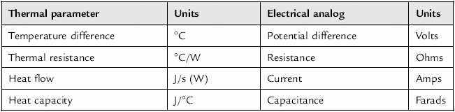
Figure 43.1 shows the simplest general model and its electrical analog. The model can be analyzed using conventional circuit theory and yields the following equation for the temperature at the heat source:
![]()

Figure 43.1 Heat transfer from hot component to ambient
This temperature is the critical factor for electronic design purposes, since it determines the reliability of the component. Reducing any of PD, Rθ or TA will minimize T. Ambient temperature is not normally under your control but is instead a specification parameter (but see section 43.4). The usual assumption is that the ambient air (or other cooling medium) has an infinite heat capacity and therefore its temperature stays constant no matter how much heat your product puts into it. The intended operating environment will determine the ambient temperature range, and for heat calculations only the extreme of this range is of interest; the closer this gets to the maximum allowable value of T the harder is your task. Since you are normally attempting to manage a given power dissipation, the only parameter which you are free to modify is the thermal resistance Rθ. This is achieved by heatsinking.
There are more general ways of analyzing heat flow and temperature rise, using thermal conductivity and the area involved in the heat transfer. However, component manufacturers normally offer data in terms of thermal resistance and maximum permitted temperature, so it is easiest to perform the calculations in these terms.
43.1.1 Partitioning the Heat Path
When you have data on the component’s thermal resistance directly to ambient, and your mounting method is simple, then the basic model of Figure 43.1 is adequate. For components which require more sophisticated mounting and whose heat transfer paths are more complicated, you can extend the model easily. The most common application is the power semiconductor mounted via an insulating washer to a heatsink (Figure 43.2(A)).

Figure 43.2 Heat transfer for a power device on a heatsink
The equivalent electrical model is shown in Figure 43.2(B). Here, Tj is the junction temperature and Rθj-c represents the thermal resistance from junction to case of the device. All manufacturers of power devices will include Rθj-c in their data sheets and it can often be found in low-power data as well. Sometimes it is disguised as a power derating figure, expressed in W/°C. The maximum allowable value of Tj is published in the maximum ratings section of each data sheet, and this is the parameter that your thermal calculations must ensure is not exceeded.
Rθc-h and Rθh-a are the thermal resistances of the interface between the case and the heatsink, and of the heatsink to ambient, respectively. Rθc-a represents the thermal resistance due to convection directly from case to ambient, and can be neglected if you are using a large heatsink.
An example should help to make the calculation clear.
An IRF640 power MOSFET dissipates a maximum of 35W steady-state. It is mounted on a heatsink with a specified thermal resistance of 0.5°C per watt, via an insulating pad with a thermal resistance of 0.8°C per watt. The maximum ambient temperature is 70°C. What will be the maximum junction temperature?
From the above conditions, Rθc-h + Rθh-a = 1.3°C/W. The IRF640 data quotes a junction-to-case thermal resistance (Rθj-c) of 1.0°C/W.
So the junction temperature:
![]()
This is just over the maximum permitted junction temperature of 150°C so reliability is marginal and you need a bigger heatsink. However, we have neglected the junction-to-ambient thermal resistance, quoted at 80°C/W. This is in parallel with the other thermal resistances. If it is included, the calculation becomes:
![]()
A very minor improvement, and not enough to rely on!
This example illustrates a common misconception about power ratings. The IRF640 is rated at 125W dissipation, yet even with a fairly massive heatsink (0.5°C/W will require a heatsink area of around 80 square inches) it cannot safely dissipate more than 35W at an ambient of 70°C. The fact is that the rating is specified at 25°C case temperature; higher case temperatures require de-rating because of the thermal resistance from junction to case. You will not be able to maintain 25°C at the case under any practical application conditions, except possibly outside in the Arctic. Power device manufacturers publish de-rating curves in their data sheets: rely on these rather than the absolute maximum power rating on the front of the specification.
Incidentally, if having followed these thermal design steps you find that the needed heatsink is too large or bulky, it will be far cheaper to reduce the thermal resistance of the total system. You do this by using two (or more) transistors in parallel in place of a single device. Although the thermal resistances for each of the transistors stay the same, the resultant heat flow for each is effectively halved because each transistor is only dissipating half the total power, and therefore the junction temperature rise is also half.
43.1.2 Thermal Capacity
The previous analysis assumed a steady-state heat flow, in other words constant power dissipation. If this is not a good description of your application, you may need to take account of the thermal capacity of the heatsink. The electrical analog circuit of Figure 43.2 can be modified according to Figure 43.3.
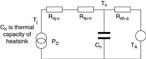
Figure 43.3 Electrical analog modified to include thermal capacity
From this you can see that a step increase in dissipated power will actually cause a gradual rise in heatsink temperature Th. This will be reflected at Tj, modified by Rθj-c and Rθc-h, which will take typically several minutes, possibly hours, to reach its maximum temperature. The value of Ch depends on the mass of heatsink metal, and its heat storage capacity. Values of this parameter for common metals are given in Table 43.2. As an example, a 1°C/W aluminum heatsink might have a volume of 120 cm3 which has a heat capacity of 296 J/°C. Multiplying the thermal resistance by the heat capacity gives an idea of the time constant, of 296 seconds.
Table 43.2 Thermal properties of common metals

The thermal capacity will not affect the end-point steady state temperature, only the time taken to reach it. But if the heat input is transient, with a low duty cycle to allow plenty of cooling time, then a larger thermal capacity will reduce the maximum temperatures Th and Tj reached during a heat pulse. You can analyze this if necessary with the equivalent circuit of Figure 43.3. Strictly, the other heat transfer components also have an associated thermal capacity which could be included in the analysis if necessary.
43.1.3 Transient Thermal Characteristics of the Power Device
In applications where the power dissipated in the device consists of continuous low duty cycle periodic pulses, faster than the heatsink thermal time constant, the instantaneous or peak junction temperature may be the limiting condition rather than the average temperature. In this case you need to consult curves for transient thermal resistance. These curves are normally provided by power semiconductor manufacturers in the form of a correction factor that multiplies Rθj-c to allow for the duty cycle of the power dissipation. Figure 43.4 shows a family of such curves for the IRF640. Because the period for most pulsed applications is much shorter than the heatsink’s thermal time constant, the values of Rθh-a and Rθc-h can be multiplied directly by the duty cycle. Then the junction temperature can now be calculated from:
![]()
where δ is the duty cycle and K is derived from curves as in Figure 43.4 for a particular value of δ⋅ PDmax is still the maximum power dissipated during the conduction period, not the power averaged over the whole cycle. At frequencies greater than a few kHz, and duty cycles more than 20%, cycle-by-cycle temperature fluctuations are small enough that the peak junction temperature is determined by the average power dissipation, so that K tends toward δ.

Figure 43.4 Transient thermal impedance curves for the IRF640
Source: International Rectifier
Some applications, notably RF amplifiers or switches driving highly inductive loads, may create severe current crowding conditions on the semiconductor die which invalidate methods based on thermal resistance or transient thermal impedance. Safe operating areas and di/dt limits must be observed in these cases.
43.2 Heatsinks
As the previous section implied, the purpose of a heatsink is to provide a low thermal resistance path between the heat source and the ambient. Strictly speaking, it is the ambient environment which is the heat sink; what we conventionally refer to as a heatsink is actually only a heat exchanger. It does not itself sink the heat, except temporarily. In most cases the ambient sink will be air, though not invariably: this author recalls one somewhat tongue-in-cheek design for a 1 kW rated audio amplifier which suggested bolting the power transistors to a central heating radiator with continuous water cooling! Some designs with a very high power density need to adopt such measures to ensure adequate heat removal.
A wide range of proprietary heatsinks is available from many manufacturers. Several types are predrilled to accept common power device packages. All are characterized to give a specification figure for thermal resistance, usually quoted in free air with fins vertical. Unless your requirements are either very specialized or very high volume, it is unlikely to be worth designing your own heatsink, especially as you will have to go through the effort of testing its thermal characteristics yourself. Custom heatsink design is covered in the application notes of several power device manufacturers.
A heatsink transfers heat to ambient air primarily by convection, and to a lesser degree by radiation. Its efficiency at doing so is directly related to the surface area in contact with the convective medium. Thus, heatsink construction seeks to maximize surface area for a given volume and weight; hence the preponderance of finned designs. Orientation of the fins is important because convection requires air to move past the surface and become heated as it does so. As air is heated it rises. Therefore the best convective efficiency is obtained by orienting the fins vertically to obtain maximum air flow across them; horizontal mounting reduces the efficiency by up to 30%.
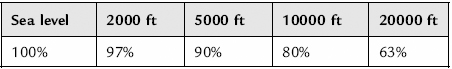
Convection cooling efficiency falls at higher altitudes. Atmospheric pressure decreases at a rate of 1 mb per 30 ft height gain, from a sea level standard pressure of 1013 mb. Since the heat transfer properties are proportional to the air density, this translates to a cooling efficiency reduction as shown in Table 43.3.
Table 43.3 Free air cooling efficiency versus altitude
The most common material for heatsinks is black anodized aluminum. Aluminum offers a good balance between cost, weight and thermal conductivity. Black anodizing provides an attractive and durable surface finish and also improves radiative efficiency by 10–15 times over polished aluminum. Copper can be used as a heatsink material when the optimum thermal conductivity is required, but it is heavier and more expensive.
The cooling efficiency does not increase linearly with size, for two principal reasons:
• longer heatsinks (in the direction of the fins) will suffer reduced efficiency at the end where the air leaves the heatsink, since the air has been heated as it flows along the surface;
• the thermal resistance through the bulk of the metal creates a falling temperature gradient away from the heat source, which also reduces the efficiency at the extremities; this resistance is not included in the simple model of Figure 43.2.
The first of the above reasons means that it is better to reduce the thermal resistance by making a shorter, wider heatsink than by a longer one. The average performance of a typical heatsink is linearly proportional to its width in the direction perpendicular to the airflow, and approximately proportional to the square root of the fin length in the direction parallel to the flow.
Also, the thermal resistance of any given heatsink is affected by the temperature differential between it and the surrounding air. This is due both to increased radiation (see below) and increased convection turbulence as the temperature difference increases. This can lead to a drop in Rθh-a at 20°C difference to 80% of the value at 10°C difference. Or put the other way around, the Rθh-a at 10°C difference may be 25% higher than that quoted at 20°C difference.
43.2.1 Forced Air Cooling
Convective heat loss from a heatsink can be enhanced by forcing the convective medium across its surface. Detailed design of forced air cooled heatsinks is best done empirically. Simulation software is available to map heat flow and the resulting thermal transfer in complex assemblies; most heatsink applications will be too involved for simple analytical methods to give better than ballpark results. It is not too difficult to use a thermocouple to measure the temperature rise of a prototype design with a given dissipation, most easily generated by a power resistor attached to a DC supply.
Figure 43.5 shows the improvement in thermal resistance that can be gained by passing air over a square flat plate, and of course at least a similar magnitude can be expected for any finned design. Optimizing the placement of the fins requires either experimentation or simulation, although staggering the fins will improve the heat transfer. When you use forced air cooling, radiative cooling becomes negligible and it is not necessary to treat the surface of the heatsink to improve radiation; unfinished aluminum will be as effective as black anodized.
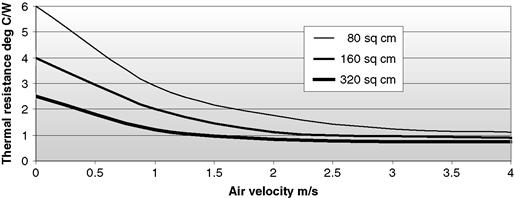
Figure 43.5 Thermal resistance vs. air velocity for various flat plate sizes
Another common use of forced air cooling is ventilation of a closed equipment cabinet by a fan. The capacity of the fan is quoted as the volumetric flow rate in cubic feet per minute (CFM) or cubic meters per hour (1 CFM = 1.7 m3/hr). The volumetric flow rate required to limit the internal temperature rise of an enclosure in which PD watts of heat is dissipated to θ°C above ambient is:
![]()
where,
ρ is the density of the medium
(air at 30°C and atmospheric pressure is 1.3 kg/m3)
Fan performance is shown as volumetric flow rate versus pressure drop across the fan. The pressure differential is a function of the total resistance to airflow through the enclosure, presented by obstacles such as air filters, louvres, and PCBs. You generally need to derive pressure differential empirically for any design with a nontrivial airflow path.
43.2.2 Radiation
Radiative cooling is something of a mixed blessing. Radiant heat travels in line of sight, and is therefore as likely to raise the temperature of other components in an assembly as to be dissipated to ambient. For the same reason, radiation is rarely a significant contribution to cooling by a finned heatsink, since the finned areas which make up most of the surface merely heat each other. However, radiation can be used to good effect when a clear radiant path to ambient can be established, particularly for high-temperature components in a restricted airflow. The thermal loss through radiation is:
![]()
where,
ε is the emissivity of the surface, compared to a black body
ΔT is the temperature difference between the component and environment
Emissivity depends on surface finish as well as on the type of material, as shown in Table 43.2. Glossy or shiny surfaces are substantially worse than matte surfaces, but the actual color makes little difference. What is important is that the surface treatment should be as thin as possible, to minimize its effect on convection cooling efficiency.
Poor radiators are also poor absorbers, so a shiny surface such as aluminum foil can be used to protect heat sensitive components from the radiation from nearby hot components. The reverse also holds, so for instance it is good practice to keep external heatsinks out of bright sunlight.
43.3 Power Semiconductor Mounting
The way in which a power device package is mounted to its heatsink affects both actual heat transfer efficiency and long-term reliability. Faulty mounting of metal packaged devices mainly causes unnecessarily high junction temperature, shortening device lifetime. Plastic packages (such as the common TO-220 outline) are much more susceptible to mechanical damage, which allows moisture into the case and can even crack the semiconductor die.
The factors which you should consider when deciding on a mounting method are summarized in Figure 43.6 for a typical plastic-packaged device.
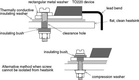
Figure 43.6 Screw mounting methods for a power device
43.3.1 Heatsink Surface Preparation
The heatsink should have a flatness and finish comparable to that of the device package. The higher the power dissipation, the more attention needs to be paid to surface finish. A finish of 50–60 microinches is adequate for most purposes. Surface flatness, which is the deviation in surface height across the device mounting area, should be less than 4 mils (0.004") per inch.
The mounting hole(s) should only be large enough to allow clearance of the fastener, plus insulating bush if one is fitted. Too large a hole, if the screw is torqued too tightly, will cause the mounting tab to deform into the hole. This runs the risk of cracking the die, as well as lifting the major part of the package which is directly under the die off the heatsink in cantilever fashion, seriously affecting thermal transfer impedance. Chamfers on the hole must be avoided for the same reason, but deburring is essential to avoid puncturing insulation material and to maintain good thermal contact. The surface should be cleaned of dust, grease and swarf immediately before assembly.
43.3.2 Lead Bend
Bending the leads of any semiconductor package stresses the lead interface and can result in cracking and consequent unreliability. If possible, mount your devices upright on the PCB so that lead bending is unnecessary. Plastic packaged devices (TO220, TO126 etc.) can have their leads bent, provided that:
• the minimum distance between the plastic body and the bend is 4 mm,
• the minimum bend radius is 2 mm,
• maximum bend angle is no greater than 90°,
• leads are not repeatedly bent at the same point, and
• no axial strain is applied to the leads, relative to each other or the package.
Use round-nosed pliers or a proper lead forming jig to ensure that these conditions are met. Metal cased devices must not have their leads bent, as this is almost certain to damage the glass seal.
When the device is inserted into the board, the leads should always be soldered after the mechanical fastening has been made and tightened. Some manufacturing departments prefer not to run cadmium plated screws through a solder bath because it contaminates the solder, and they may decide to put the screws in after the mass soldering stage. Do not allow this: insist on hand soldering or use different screws.
43.3.3 The Insulating Washer
In most devices, the heat transfer tab or case is connected directly to one of the device terminals, and this raises the problem of isolating the case. The best solution from the point of view of thermal resistance is to isolate the entire heatsink rather than use any insulating device between the package and the heatsink. This is often not possible, for EMI or safety reasons, because the chassis serves as the heatsink, or because several devices share the same heatsink. Some devices are now available in fully isolated packages, but if you aren’t using one of these you will have to incorporate an insulating washer under the package.
Insulating washers for all standard packages are available in many different materials: polyimide film, mica, hard anodized aluminum and reinforced silicone rubber are the most popular. The first three of these require the use of a thermally conductive grease (heatsink compound) between the mating surfaces, to fill the minor voids which exist and which would otherwise increase the thermal resistance across the interface. This is messy and increases the variability and cost of the production stage. If excess grease is left around the device, it may accumulate dust and swarf and lead to insulation breakdown across the interface. Silicone rubber, being somewhat conformal under pressure, can be used dry and some types will outperform mica and grease.
Table 43.4 shows the approximate range of interface thermal resistances (Rθc-h) that may be expected. Note that the actual values will vary quite widely depending on contact pressure; a minimum force of 20N should be maintained by the mounting method, but higher values will give better results provided they don’t lead to damage. When thermally conductive grease is not used, wide variations in thermal resistance will be encountered because of differences in surface finish and the micro air gaps which result. Thermal grease fills these gaps and reduces the resistance across the interface. Despite its name, it is not any more thermally conductive than the washer it is coating; it should only be applied very thinly, sufficient to fill the air gaps but no more, so that the total thickness between the case and the heatsink is hardly increased. In this context, more is definitely not better. The mounting hole(s) in the washer should be no larger than the device’s holes, otherwise flashover to the exposed metal (which should be carefully de-burred) is likely.
Table 43.4 Interface thermal resistances for various mounting methods

43.3.4 Mounting Hardware
A combination of machine screws, compression washers, flat washers and nuts is satisfactory for any type of package that has mounting holes. Check the specified mounting hole tolerances carefully; there is a surprisingly wide variation in hole dimensions for the same nominal package type across different manufacturers. A flat, preferably rectangular (in the case of plastic packages) washer under the screw head is vital to give a properly distributed pressure, otherwise cracking of the package is likely. A conical compression washer is a very useful device for ensuring that the correct torque is applied. This applies a constant pressure over a wide range of physical deflection, and allows proper assembly by semi-skilled operators without using a torque wrench or driver. Tightening the fasteners to the correct torque is very important; too little torque results in a high thermal impedance and long term unreliability due to over-temperature, while too much can overstress the package and result in long term unreliability due to package failure.
When screw-mounting a device which has to be isolated from the heatsink, you need to use an insulating bush either in the device tab or the heatsink. The preferred method is to put the bush in the heatsink, and use large flat washers to distribute the mounting force over the package. You can also use larger screws this way. The bush material should be of a type that will not flow or creep under compression; glass-filled nylon or polycarbonate are acceptable, but unfilled nylon should be avoided. The bush should be long enough to overlap between the transistor and the heatsink, in order to prevent flashover between the two exposed metal surfaces.
A fast, economical and effective alternative is a mounting clip. When only a few watts are being dissipated, you can use board mounting or free standing dissipators with an integral clip. A separate clip can be used for larger heatsinks and higher powers. The clip must be matched to the package and heatsink thickness to obtain the proper pressure. It can actually offer a lower thermal resistance than other methods for plastic packages, because it can be designed to bear directly down on top of the plastic over the die, rather than concentrating the mounting pressure at the hole in the tab. It also removes the threat of flashover around the mounting hole, since no hole is needed in the insulating washer.
When you have to mount several identical flat (e.g., TO-220) packages to a single heatsink, a natural development of the clip is a single clamping bar that is placed across all the packages together (Figure 43.7). The bar must be rigid enough and fixed at enough places with the correct torque to provide a constant and predictable clamping pressure for each package. With suitably ingenious mechanical design, it may also contribute to the total thermal performance of the whole assembly.

Figure 43.7 Package clamping bar
43.4 Placement and Layout
If you are only concerned with designing circuits that run at slow speeds with CMOS logic and draw no more than a few milliamps, then thermal layout considerations will not interest you. As soon as dissipation raises the temperature of your components more than a few tens of degrees above ambient, it pays to look at your equipment and PCB layout in terms of heat transfer. As was shown in the last chapter, this will ultimately reflect in the reliability of the equipment.
Some practices that will improve thermal performance are:
• Mount PCBs vertically rather than horizontally. This is standard in card cages and similar equipment practice, and it allows a much freer convective airflow over the components. If you are going to do this, do not then block off the airflow by putting solid metal screens above or below the boards; use punched, louvred or mesh screens.
• Put hot components near the edge of the board, to encourage a good airflow around them and their heatsinks. If the board will be vertically mounted, put them at the top of the board.
• Keep hot components as far away as possible from sensitive devices such as precision op-amps or high failure rate parts such as electrolytic capacitors. Put them above such components if the board is vertical.
• Heatsinks perform best in low ambient temperatures. If you are using a heatsink within an enclosure without forced air cooling, remember to allow for the steady-state temperature rise inside the enclosure. However, don’t position a heatsink near to the air inlet, as it will heat the air that is circulating through the rest of the enclosure; put it near the outlet. Don’t obstruct the airflow over a heatsink.
• If you have a high heat density, for example a board full of high speed logic devices, consider using a thermally conductive ladder fixed on the board and in contact with the IC packages, brought out to the edge of the board and bonded to an external heatsink. PCB laminates themselves have a low thermal conductivity.
• If you have to use a case with no ventilation, for environmental or safety reasons, remember that cooling of the internal components will be by three stages of convection rather than one: from the component to the inside air, from the inside air to the case, and from the case to the outside. Each of these will be inefficient, compared to conductive heat transfer obtained by mounting hot components directly onto the case. But if you take this latter course, check that the outside case temperature will not rise to dangerously high levels.