In this chapter, I present best practice suggestions and offer a balanced explanation so that you can evaluate the benefits and potential problems associated with in-context modeling. I give you enough facts so that you can decide for yourself how in-context techniques fit into your process.
In-context modeling is an extremely powerful technique for extending parametric design from individual parts to top-level assemblies. With the power comes potential for mistakes. If you are not careful, in-context modeling can lead to unexpected results.
In-context modeling is also known as top-down modeling. It is a technique used to create relationships between parts in the context of an assembly, where the geometry of one of the parts is controlled by both the other part and the mates that position them relative to one another.
In-context, or top-down, modeling may be contrasted against bottom-up modeling. Bottom-up modeling involves making the parts in their own individual windows and assembling the finished parts into an assembly with mates.
In its most common form, a sketch in one part in an assembly is related to an edge in another part in the assembly. The relationship is specific to that particular assembly, and is only relevant in the context of that assembly. For example, you may create a box and put it into an assembly. You must then create a lid that is parametrically linked to the size and shape of the box. You can create a lid part in the context of the assembly such that the lid always matches the box. Sketch relationships, dimensions, and feature end conditions from the lid can reference the box. When the box changes, the lid also changes if the assembly is open.
The assembly maintains a record of each in-context reference. If the box is changed with both the assembly and the top open, then the top updates, but if the box is changed without the assembly being open, then the lid will not update until the assembly is opened. The record of the reference that the assembly maintains is held in what is called an update holder, and in recent versions, it is all but forgotten.
Cross-Reference
Chapter 12 discusses in-context reference update holders. These are the pointers in the assembly that hold the reference information. These holders are hidden by default and do not enable any real functionality, but they do serve as a reminder that the assembly has in-context references and can be queried to tell you what parts the in-context relations go between.
The advantages of in-context modeling are obvious. I spent the first couple of chapters of this book discussing the strengths of parametric design, and in-context modeling is just an extension of parametric techniques to include parts in the context of an assembly. Making a change to one part and having all related parts update offers indisputable advantages.
Some users approach modeling haphazardly, where if it works, it's good enough. For some types of work, this is acceptable and "good enough." For example, it usually works when you create something that will never be changed or if you are working on concept models.
On the other hand, users who need to build models that will be reused frequently and changed often must approach the decisions they make during modeling as if they were playing chess: Each decision has consequences; you rarely know exactly how things are going to turn out but need to prepare for the most likely contingencies.
In-context modeling presents the same types of decisions. You can do it fast and dirty or methodically and with much consideration beforehand.
Some issues may arise from the technique of driving changes from a different part model within an assembly. There are no problems with the overall concept of in-context modeling; the problems occur with the practical application of the technique. In particular, the biggest problems seem to arise when in-context techniques are combined with other techniques. You must be very careful about file management issues when in-context references exist in your assembly.
Major potential problems include:
Lost references due to renamed assemblies
Convoluted references causing long rebuild times
Circular references causing changes with each rebuild
Frustrated users who don't understand how to manage change in an in-context scheme
However, you can overcome these difficulties. In the rest of this chapter, I show you how to make the most of in-context modeling.
The kinds of problems users typically have with in-context modeling are related to file management. Inexperienced users may rename a file and break links, or try to use an in-context part in some location other than where the in-context relation was created, and may not be able to make changes that they want to make, or changes happen when they do not want them to.
Sometimes these problems are the result of the user simply not understanding what to expect from the tool, and sometimes it is because the tool is not capable of what they are trying to achieve. Right or wrong, many users have developed an irrational fear of references that can control a part from outside of the part itself. In-context modeling in itself is not a bad technique, but sometimes it is not the best option. I recommend thoroughly understanding in-context and all related techniques before passing judgment on any of the techniques.
It's always important to identify alternative techniques because one tool never solves all possible problems. In-context modeling is powerful, but in some situations other techniques are better suited. In this case I want to introduce you to a couple of techniques that share with in-context the ability to control individual parts from a centralized location, but achieve that in ways that are somewhat different: Assembly layout modeling enables you to control individual parts not from other parts, but from an assembly level sketch. Multi-body modeling enables you to control several parts from a single part without worrying about the file management issues of having another assembly as the middle agent.
Assembly layouts are powerful tools that remove much of what some people object to in in-context modeling. Relationships in this technique are controlled by top-level sketches, where a single or multiple sketches can control most of the features on all parts through relationships between part sketches or features and the assembly sketch. This still creates an external reference that requires the existence of an assembly to update the relationships, but it is not a direct link between different parts in the context of the assembly.
Assembly layouts do not lend themselves well to dynamic assembly motion, but they are great for having a single location to drive an entire assembly. Assembly layouts come in two flavors, the generic layout which is simply done using sketches in an assembly; and the formal Layout feature, which is essentially a 3D sketch in the assembly with special properties. The Layout feature is described in more detail later in this chapter. Assembly layout sketches are covered in more detail in Chapter 12.
Multi-body modeling, like in-context modeling, is a powerful technique with positives and negatives. If you model what will later turn out to be separate parts together in a single part, you can avoid in-context modeling altogether. It is not recommended that you replace assemblies with multi-body modeling for a number of reasons, such as limitations of multi-body techniques for common assembly operations like dynamic assembly motion and interference detection. Used judiciously, multi-body modeling can help you save time making models that hold up well to changes. Multi-body modeling is discussed in depth in Chapter 26, along with a direct comparison to assembly modeling and a justification for why you shouldn't replace assemblies with multi-body parts.
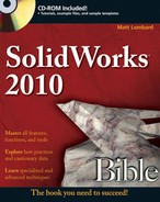
Figure 16.1 shows a simple box with the sketch of a simple top for the box. Notice in the FeatureManager that two parts are listed as the top and base. The .050-inch offset is creating a sketch in the top part that is driven by the edges of the base part. This simple assembly demonstrates the in-context process in the sections that follow.
You can perform in-context modeling using one of two basic schemes. You can build parts from the very beginning in the context of the assembly (using the Insert
The InPlace mate clamps the part down to any face or plane where it is applied. It is meant to prevent the in-context part from moving. I will explain later in this chapter why it is so important for in-context parts not to move.
Sketches, vertices, edges, and faces from the other parts in the assembly can be referenced from the in-context part as if they were in the same part as the sketch. Most common relations are concentric for holes, and coincident for hole centers. Converted entities (On-Edge relations) make a line-on-edge relation between the parts, and Offset sketch relations are also often used.
Other types of valid in-context relations include in-context sketch planes and end conditions for extrude features such as Up to Face and Up to Body. Beyond that, you can copy surfaces from one part using the Knit Surface feature or the Offset Surface feature. I discuss surfacing in more detail in Chapter 27.
When you are working in-context or using in-context data, visual cues offer information about the part that you are working on. The following topics are meant to help you understand what is going on while you are working in-context.
When you are working in-context, the FeatureManager text of the part that you are working on turns blue. This should make it immediately obvious first that you are working in-context, and, second, which part is being edited.
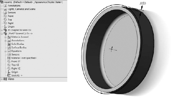
You can control the color and transparency behavior of parts in the assembly where a part is being edited in-context by choosing Tools
The Tools

The options in the Assembly Transparency drop-down list are
Opaque Assembly. All parts that are not being edited when an assembly component is being edited in-context turn opaque, even if they are otherwise transparent.
Maintain Assembly Transparency. Leaves all assembly components in their default transparency state.
Force Assembly Transparency. Forces all the parts, except for the one being edited in the assembly, to become transparent.
These options reflect personal preference more than anything else, but it is useful to have a reminder as to whether a part is being edited in the assembly or the assembly document is being edited in its own window.
Tip
The color selected in the box shown in Figure 16.2 controls both the text color and the color of the part shown in the graphics window.
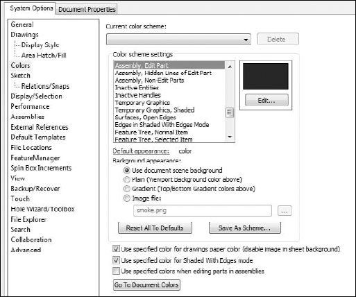
Second, you can use the Edit Component button to begin or finish editing a part that is already in an assembly. When you are editing a part in the context of an assembly, the title bar of the SolidWorks window reflects the fact that you are editing a part in an assembly, the toolbar changes to a part-editing toolbar, and the lower-right corner of the taskbar displays the words Editing Part, as shown in Figure 16.4.
Third, a confirmation corner image exists in the upper-right corner of the graphics window when you are editing a part in the context of the assembly. This makes it easier to exit Edit Component mode.
Editing a component can also mean editing a subassembly in the context of the top-level assembly. You can create in-context assembly features and mates if necessary; however, you will do this far less frequently than editing parts in-context.
Note
Creating in-context relations is not the only reason to edit a part or subassembly in the context of the top-level assembly. Sometimes it is simply more convenient to do normal editing when you are in the top-level assembly; this way you can see how the part relates to other parts after making changes in the assembly without making relations between the parts.
Editing a subassembly in the context of the upper-level assembly is often useful as well, to see how changing subassembly mates affects the top level.
Probably the most common mistake you can make with in-context editing has to do with editing the part versus editing the assembly when they add a sketch. If you intend to add a sketched feature to a part in the context of an assembly, but you fail to switch to Edit Part mode before creating the sketch, then the sketch ends up in the assembly rather than the part; you can only do limited things with a sketch in an assembly. Likewise, if you intend to make an assembly layout sketch, but you do not switch out of Edit Part mode, you end up with a sketch in a part that cannot do what you want it to do.
Fortunately, SolidWorks has added a remedy for the first situation. When you make a sketch in the assembly but need to make a feature in the part, you can choose the Propagate feature to parts option in the Feature Scope area of the PropertyManager for the feature, as shown in Figure 16.5.
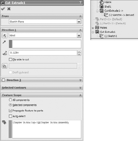
Notice in the image on the right that the last sketch in the part appears as derived. This means that the sketch and the feature are still driven from the assembly, but they have been propagated to the part enough to allow the feature to be edited in the part. I wouldn't go this route just because you made a mistake and it's simpler to do this than to move the sketch to the part, but it is an option that is valid in some situations.
Interestingly, this feature cannot be deleted from the part; you must delete it from the assembly.
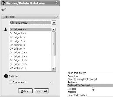
The external reference symbol appears as a dash followed by a greater-than sign (->). External references indicate more than just in-context features. You can also create external references by using the Split Part command as well as the Insert Part (base or derived part) or the mirrored part functions. Figure 16.6 shows the expanded FeatureManager for a part with an in-context reference in a sketch.
External references can have four states, which Figure 16.6 shows. These are
In-context (->)
Out-of-context (->?)
Locked reference (->*)
Broken reference (->x)

In-context ->
The in-context symbol signifies that the relation created between two parts within the current assembly is fully resolved. It can find both parts involved in the relationship and the assembly where the relationship that was created is active.
Out-of-context means that the document — usually but not necessarily an assembly — where the reference was created is not open at the time. It is indicated by an in-context symbol followed by a question mark. You can open the document where the reference was created by clicking the right mouse button (RMB) and selecting the Edit In Context option from the menu. Edit In Context opens either the parent part of an inserted part or the assembly where the reference was created for an in-context reference. When you open the referencing document, the out-of-context symbol changes to the in-context symbol.
Locked reference ->*
You can lock external references so that the model does not change, even if the parent document changes. The symbol for this is ->*. Other features of the part may be changed, but any external reference within the part remains the way it is until the reference is either unlocked or removed. In the top and base example I mentioned earlier, this means that if the Bottom part is changed, and the external reference on the Top is locked, then the Top will no longer fit the Bottom.
One of the best things about locked references is that you can unlock them. They are also flexible and give you control over when updates take place to parts with locked references.
Broken reference ->x
The broken reference is another source of controversy. Some users believe that if you make in-context references, the best way to respond to them is to break them immediately. However, I would argue that using the Break References function is never a good thing to do. I believe that you should remove the reference by editing the feature or the sketch or change it to make it useful.
The problem with a broken reference is that it has absolutely no advantage over a locked reference. For example, while locked references can at least be unlocked, broken references cannot be repaired. The only thing that you can do with a broken reference is to use Display/Delete Relations or to manually edit features to completely remove the external reference. Perhaps it would be better for SolidWorks to replace Break References with a function called Remove References. Would anyone like to make an enhancement request?
Best Practice
Best practice is to not put yourself in a situation where you are using broken references. Parametric relations should not change if the driving geometry does not change.
You cannot selectively lock or break external relations. For example, all the external relations in the part can be locked, all the external relations can be broken, or none of them can be locked or broken. If you need to selectively disable relations, then you should consider suppressing features, sketch relations, end conditions, or sketch planes.
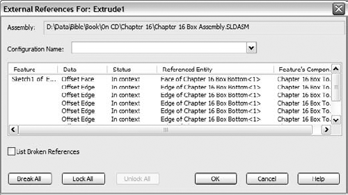
You can access the locked and broken references through the List External References option on the RMB menu of any feature with an external reference symbol. Figure 16.7 shows the name and path of the assembly where the external reference was created, as well as the part names and entity types.
This lack of references includes the InPlace mate, which is not created when a part is created in-context. As a result, when you add the part to the assembly, if you exit and later re-enter Edit Part mode, SolidWorks reminds you that the part is not fixed in space by displaying the warning shown in Figure 16.8.
This message should remind you that in-context features should be used only on parts that are fully positioned in the assembly.

However, this is a technique that requires a fair amount of discipline, restraint, foresight, and judgment. The potential problems associated with overuse or misuse of in-context techniques primarily include performance problems (speed) and lost references due to file management issues. Users may also experience problems with features or sketches that change with each rebuild. The following section contains best practice suggestions that can help you avoid these situations.
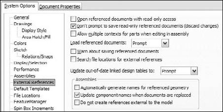
Multiple contexts occur when a part has references that are created in multiple assemblies. By default, multiple contexts are prevented from happening. If you place a part that already has external references into a different assembly, a warning appears, as shown in Figure 16.10.
Although SolidWorks displays many warnings about multiple contexts, you may still run into situations where you need to use them. For example, you may have a subassembly where a part, such as a top plate of a stand, has in-context references to locate a set of mounting holes for legs of the stand. When you place the subassembly into the top-level assembly and mount another assembly to the top plate, another set of in-context holes is required in the top plate.
Figure 16.11, at the top, shows the first table and points out the in-context relations. At the bottom, the large bracket appears for the machine that is mounted to the table top using more in-context relations. The External References dialog boxes for the two different in-context features appear in Figure 16.12. Notice that the Assembly fields at the top of the External References dialog boxes are different. You can only achieve this by selecting the Allow multiple contexts for parts when editing in assembly option shown in Figure 16.9.
Note
The Tools
Multiple context modeling is something that should be the exception rather than standard practice. If you do not have all the assemblies open where the in-context references were created, then you will have some out-of-context references. This can make for a troubleshooting nightmare if someone ever has to try to reconstruct how the assembly is driven.
The best practice is to avoid creating multiple-context references. If you need to do this, then be very careful about naming files, and remember to turn off the multiple-context option when you have finished creating the reference.


If you receive a multiple-context part from someone else, the best thing to do is to determine whether you have all the files required to make it work. Right-click the external reference symbol and select Edit In Context to determine whether SolidWorks can find the right files. Also looking for an out-of-context symbol will tell you if any of the necessary files are not currently open.
Aside from doing some programming, the only way to find out whether a part was created as a multiple-context part is to examine the External References list for each in-context feature. This can be very time-consuming. Although multiple-context parts should be very rare, it is impossible to determine ahead of time whether or not a part that you have received is a multiple-context part, at least without programming. The one exception to this is when some features are in-context and some are out-of-context.
On the surface, mixing in-context references with configurations sounds like it is combining two powerful techniques that should offer you great control over models. Although this may sometimes be true, I want to caution you about some of the effects that combining these two techniques may cause. In particular, you should be careful about part configurations, particularly configurations of the referenced part.
If you are using in-context relations to parts with configurations, then you may want to consider a few things. First, look at the door-hinge part shown in Figure 16.13. At the top are three configurations of one of the hinge plates. The second hinge plate is built in the context of the assembly so that it will always match the first plate. At the bottom are the results of changing the first hinge-plate part configuration in the assembly. This looks like an ideal situation because the second hinge plate always changes to match the first hinge plate. What could be wrong with this?
The problem here is that you can only show the size of the second hinge plate that corresponds to the configuration of the first plate that is active in the assembly. If you had two instances of the hinge assembly in a top-level assembly, then you would be able to show only one size for the second plate.

A second situation where combining in-context references and configurations can cause you trouble is if you have referenced the edges of a part from another part, and a configuration of the referenced part either adds or removes fillets or chamfers, thus breaking the edges. Either of these situations can cause the in-context sketches or other features to fail. This may be a reason to reference the underlying sketches, rather than the model edges or faces themselves.
In some situations, configurations work well with in-context relations. One example of this would be when an assembly has many configurations used for positioning parts. In this case, use one configuration for the sole purpose of creating in-context relations.
You should make in-context references between parts where there is no relative motion. The parts themselves can move relative to the rest of the assembly, but they should remain stationary relative to one another. The parts should also be fully defined to ensure that they will not move; you should not simply count on avoiding dragging underdefined parts.
In some cases, such as an assembly of imported parts, it may make sense to fix parts in bulk rather than to mate them. When you are using in-context relations, you need to take extra care to ensure that the parts do not move around. When parts move around, in-context features also move.
Obviously, if the motion is around a circular hole and the in-context feature is circular and is not affected by the rotation of the referenced part, then it makes less difference; however, if there is a keyway, that may change things. You need to pay attention when combining underdefined parts and in-context features.
Best Practice
For best practice, you should avoid in-context relations between parts when relative motion is allowed between these parts.
Another situation that can cause problems is when multiple instances of an in-context part are being used in the assembly. In cases like this, you need to be careful and consistent, by always using the same instance to create the in-context relations. You can do this by putting parts into folders, or by giving the in-context part a special component color.
One trick used by some people is to use one instance of an in-context part for the in-context relation, and a second instance of the part to allow motion. In-context relations are tied to one specific instance of a part, regardless of how many of those parts are in the assembly. You might want to set the driving in-context part aside by putting it in a folder, changing its color, or hiding it.
Understanding what you are doing with file management is imperative when working with parts that depend on in-context features. Because the references are stored in both the part that is doing the referencing and the assembly where the reference is created, improperly changing the name of either document or even the referenced document is bound to cause problems. For example, if you rename an in-context part using Windows Explorer, then the assembly will not recognize the part, as I demonstrated in an earlier chapter. This also means that any in-context references will not update. The part will show the out-of-context symbol.
For best practice, you should use either the SolidWorks Save As command or SolidWorks Explorer to rename parts and assemblies. This applies to all parts and assemblies, but doubly to in-context documents.
I mentioned this earlier, but a section on in-context best practices would not be complete without issuing the warning against mating to in-context features. Mating parts to in-context features creates a parametric daisy chain, thus establishing an order in which assembly features and mates must be solved. This always creates performance problems in assemblies, especially large ones. The SolidWorks AssemblyXpert looks for this condition when examining assemblies.
Circular references in assemblies are a bigger problem than most people realize. In fact, most people do not realize that circular references are a problem, or, for that matter, that they even exist.
A circular reference takes the form of "Part A references Part B, which references Part A." It creates a circular loop that really wrecks assembly rebuild times. Part feature design trees are not susceptible to this sort of looping because the part FeatureManager operates in a linear fashion (at least when it comes to applying relations between sketches or features).
The Assembly FeatureManager is solved in this order, or an order that is very similar:
Solve reference geometry and sketches that are listed before parts in order, at the top of the design tree.
Rebuild individual parts as necessary.
Solve the mates and locate the parts.
Solve in-context features in parts.
Solve reference geometry and sketches listed after the mates.
Solve assembly features and component patterns.
Loop to Step 3 to solve mates that are connected to anything that was solved after the first round on the mates.
Continue to loop until complete.
As you can see, even if you do not have a reference such as "Part A references Part B, which references Part A," it is still possible to get a highly convoluted, if not entirely circular, loop. Many users with smaller assemblies in the hundreds of parts complain about very poor performance.
When you are making in-context references, a technique that can help you avoid circular references is to always create references to parts that are higher in the design tree. You can expand on this idea until a single entity is at the top of the design tree, to which all in-context references are made. This could take the form of a layout sketch, or a skeleton. These concepts are discussed in Chapters 11, 12, and 13. I discuss the Layout feature, which is different from the layout sketch, later in this chapter as an additional in-context tool.
Remember that the layout sketch consists of a single or even multiple sketches that control the overall layout of the assembly, as well as all the relationships between parts. When you refer all the relations to a single entity that does not change with part configurations, or lose or gain filleted edges, the intra-part parametrics become much stronger and more stable.
When you are building a mold for plastic injection molding, a single sketch can control the size and position of the plates, pins, and so on. If all the 3D parts are mated to the 2D sketch, or use the 2D sketch by converted entities, then the parts will move with the sketch. This same technique is important and useful for any type of die or punch design, along with many other types of design.
Library parts should never contain in-context references, especially if the in-context references are out of context. Small library assemblies may have in-context references between the parts, but a single part should not have features created in-context. External references may be unavoidable in the form of mirrored or inserted parts, but in-context references are completely avoidable.
If you are considering using the Break Relations tool, then you should either reconsider and use Lock Relations instead or simply remove all the in-context relations altogether.
Other types of in-context references are not as easy to remove as sketch relations. When you see the External Reference symbol on a sketch, it could be the sketch relations or it could be the sketch plane that was in-context. In order to remove the reference from an in-context sketch plane, you must redefine the plane locally in the part.
You should also not forget end conditions such as Up To Surface, Offset From Surface, or even From Surface. If an external reference symbol remains on a feature, you can use the Parent/Child option on the RMB menu to locate it. Remember that using an edge or vertex for a plane definition can cause an in-context relation.
In-context is initially so fast and easy to use that it can be addictive, but you need to think before you use it because of the speed and file management implications these relations will have later on in your design process.
If someone else needs to use your model after you are done with it and possibly edit it, then you should leave some clues to help this person understand how the model works, and how it is best changed. For example, you can use descriptive feature and sketch names, comments that are associated with features, the Design Binder to add documentation, and the Design Journal to write notes. You can even put HTML (Hypertext Markup Language) links in notes that display in the graphics window.
In-context design intent may not always be obvious, and an impatient user may find it more expedient to delete the in-context references and replace them with either local relations or no relations at all. The more you document your intent, the more likely others will be to follow it.
The external reference symbol (- >) indicates in-context features that have been created in the context of an assembly, but it also indicates three other types of external references —Inserted parts, split parts, and mirrored parts.
I discuss inserted parts to some extent in Chapter 10, and in more detail in Chapter 28. In the past, inserted parts have also been called base parts and derived parts, and some users still use those names.
An inserted part is simply an entire part that has been inserted into another part. This is sometimes referred to as a pull operation because the data is pulled from the original part into the child part. The part may be inserted at any point in the history of the design tree, and it may create an additional body within the part or be added to the existing one. Additional features can also be added to the inserted part.
Items that can be brought along with the inserted part are solid bodies, surface bodies, planes, axes, sketches, cosmetic threads, and even features. You can also use a particular configuration of the inserted part in the child part. I discuss this aspect in Chapter 14, dealing with configurations, and also in Chapter 28, dealing with master models.
You can use inserted parts for many modeling applications, such as cast parts and secondary operations. You first insert the original cast part into a new blank part. Then you add cut and hole features until the part resembles the finished part.
Another application for inserted parts is a single part that has been built from several models. For example, I once worked on a large, rather complicated plastic basket, where the basket was modeled as three individual parts, and then reassembled into a single part. Another application may be to insert a part as a body into a mold block to create a mold cavity. To insert a part into another part, you can choose Insert
I discuss split parts in detail in Chapter 28, in the section about master models. Inserted and split parts are both master model techniques, as are a few more techniques that I discuss in Chapter 28. Some people also include in-context techniques with the master model tools because this is a way of making several parts update together.
Split parts are sometimes called a push operation because the data is pushed from the original multi-body part to the individual child parts. The split function takes a single body and splits it into several bodies, optionally saving the bodies out as individual parts. This is done for various reasons, such as creating a single, smooth shape out of several different parts; for example, automobile body panels or the various covers and buttons on a computer mouse. You can use the split parts technique for other applications, as well. Sometimes a product is designed as a simple, single solid to keep the modeling simple, and because it is not known how the parts will be assembled or manufactured. When the manufacturing decisions are made, the part can be split into several models that have the engineering details added to them.
You can mirror a right-handed part to create a left-handed part. To activate the Mirror Part command, you must select a plane or planar face. Then choose Insert
Mirror parts can also use configurations, and so if you have one of those "mirrored exactly except for . . ." parts, you can select the configuration of the parent from the child document.
The Layout feature is simply a 3D sketch that is given special treatment within an assembly. It works best with sketch blocks. To initiate a Layout, click the Layout button on the Layout tab of the assembly CommandManager or activate it from the Insert menu. Once you are in a Layout, SolidWorks puts you into a 3D sketch with the Front (XY) plane activated, so it displays a small grid.
Cross-Reference
3D sketches are addressed in Chapter 31.
For now, you primarily treat the 3D sketch as much like a set of 2D sketches as possible. The main difference is that you can double-click on a different plane to start sketching on the new plane, and you will always see this small grid when a plane is active.
3D sketches have some limitations when you are working with Layouts, such as lacking the capabilities to use sketch patterns and Sketch Pictures.
Here is the general workflow for working with the Layout feature:
Open a new or existing assembly.
Click the Layout toolbar button on the Layout tab of the CommandManager.
Sketch on the plane in the 3D sketch to create 2D sketches representing parts of a mechanism or other assembly.
Make selections of the sketch into blocks representing individual parts.
Insert multiple instances of the blocks to represent multiple instances of the parts.
Use sketch relations to put the blocks together like mating parts in an assembly.
Test the mechanism by dragging sketches. (Blocks function like a single sketch entity, so you can drag them within the sketch like parts in an assembly.)
Right-click the block (from inside or outside the Layout) and select Make Part From Block (also a button on the Layout toolbar), as shown in Figure 16.15.

Virtual components always exist with in-context workflows, and frequently with the Layout workflow. Virtual components are parts that are saved within the assembly. You can save a virtual component externally, and you can also make an externally saved part into a virtual component.
The advantages of virtual components are that you don't have to worry about saving out additional files, plus the assembly will never lose track of any virtual component.
Virtual components are primarily intended to be used as quick, temporary, conceptual tools, rather than as a way to make parts that will be a permanent part of the assembly. I have also seen some SolidWorks users use virtual components to represent non-geometric parts such as glue or paint. Any time you choose Insert
Virtual components are named Part1^Assem1, where Part1 and Assem1 are default names. You can easily rename the part by clicking the RMB menu and selecting Rename Part. You cannot do this for external parts. If you make an external part virtual, the name in the assembly becomes Copy of file name^Assem1 where file name was the name of the external file. The name of the assembly is always included (and cannot be removed) to ensure that if you have subassemblies that also have virtual components, you will always have unique filenames for all the parts.
Virtual components can also be accessed in their own window, which makes them easier to edit for some purposes. Bills of Materials (BOMs) and numbered balloons work correctly with virtual components.
Best Practice
It is considered best practice to save any parts that will be a permanent part of the assembly as external files. Virtual components should be limited to temporary parts or possibly non-geometry, BOM-only parts like glue or paint.
In theory, the Layout feature has several advantages:
In practice, this feature needs some enhancements before it is ready for use on real assemblies. While attempting to create a Layout tutorial for this chapter, I came across several limitations that would make the tutorial unmanageable, and I think you will agree that using 2D sketches as assembly layout sketches is still a better idea than trying to avoid the limitations of the formal Layout feature. The limitations listed are presumably not bugs because Layout was introduced in 2009 and this testing was done on 2010 SP 0.0. Here are some of the limitations of Layout:
The 3D sketch used for Layout has all the limitations that come with 3D sketches.
Sketch relations are listed in the Mates folder.
Gaining access to edit the Layout once it has been closed requires a method you don't expect from a sketch: you click the Layout button on the toolbar rather than right-click and edit an icon in the FeatureManager.
It requires that you use blocks to get all of the functionality.
A fully defined 3D sketch with blocks is very unstable.
Part creation from blocks does not offer a time savings.
You cannot paste copied sketch entities from a 2D sketch into the Layout.
You cannot use autodimension (or polygons or ellipses) in the Layout.
Although the formal Layout feature has serious advantages over regular layout sketches, at this time the limitations outweigh them. The rest of my discussion on layouts addresses the generic layout technique rather than the formal feature.
Follow these steps to get a feel for the workflow of working with parts in the context of an assembly:
Open the assembly from the CD-ROM named Chapter 16
Tutorial Table.sldasm.
Set the Assembly Edit Part color to a shade of blue, and the Assembly Non-Edit Parts to a shade of gray.
Also set the Assembly transparency for in context edit setting to Force Assembly Transparency, with the slider at around 90 percent.


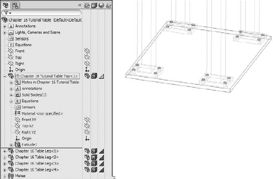
Now select the 16 hole edges on the legs. It does not matter whether you select the top edges or the bottom, or even a combination of top and bottom. Use the Convert Entities command to project the edges into the sketch plane as circles, as shown in Figure 16.17.
Create a cut that goes Through All. You may have to change the direction of the extrude to get it to work. Exit Edit Component mode using the confirmation corner and save the tutorial assembly.
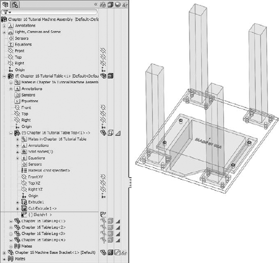
Now open the file named Chapter 16
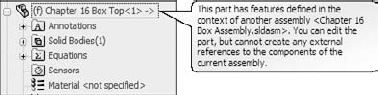
Tutorial Machine Assembly.sldasm. Notice that the Table Top part in this assembly is using the Wireframe display state, which is assigned in the Display pane.Right-click the part and select Edit Part from the list, or select the part and click the Edit Component button on the toolbar. A warning will display that the part has features that were created in the context of another assembly. You can edit the part, but you cannot add any more external references (in-context features) to it.
Toggle off the Edit Component button on the Assembly toolbar to exit Edit Part mode.
Choose Tools

Make sure that you are editing the Table Top part. It will not change colors as specified in the Tools
Open a sketch on the Front plane, and convert the four edges of the holes, as shown in Figure 16.18.
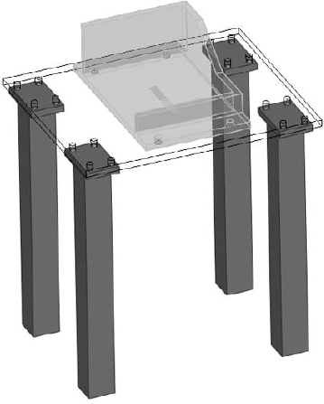
Cut the holes using the Through All setting. Again, be aware of the direction of the cuts. Toggle out of Edit Component mode and press Ctrl+S to save the assembly. Figure 16.19 shows the finished assembly.
Open the Machine Base Bracket part in its own window by selecting Open Part from the RMB menu. The part is shown in Figure 16.20.
Select the Front plane and choose Insert
Mirror Part. This creates a new part and opens a new PropertyManager interface, as shown in Figure 16.21.

Note
Notice that I used the Insert
Cross-Reference
I discuss the function of Mirror/Insert part in more depth in Chapter 26.


Notice that the new part is indeed a mirrored copy of the original. You can see that the "MADE IN USA" text on the bottom is backwards. Fortunately, a configuration exists specifically for this purpose. Change the configuration by selecting For Mirroring in the Configuration Name drop-down list in the External References dialog box (from the RMB selection List External References), as shown in Figure 16.22. Notice that this configuration removes the extruded text from the model.
Add your own "MADE IN . . ." extruded text to the bottom of the part. Save the part.

In this tutorial, you will use regular assembly sketches to lay out and build a tooling die.
Open the assembly from the CD-ROM named Chapter 16
tutorial layout start.sldasm. Notice that three layout sketches and some of the parts have been added already. The existing parts are virtual components, saved inside the assembly.


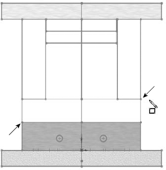
Be careful not to click on model faces, edges, or vertices when creating these depth references. Make sure that all your references stay in the sketch.

Follow this procedure for four remaining plates, as shown in Figure 16.24. To summarize the steps again, they are add new part, create sketch, extrude block.
Note
Be careful with the plates labeled 5, 6, 7, and 8. There is a clearance gap between the sides of the 7 and 8 plates and the vertical plates 5 and 6.
Reorient the view to the Top view. Make sure you can see the Pin Layout sketch.

Place two sketch points at the centers of the circles, as shown in Figure 16.25. Make sure that the two points are both over the same plate 5 or 6. You cannot cut both plate 5 and 6 in the same Hole Series feature. Use the settings shown in Figure 16.25.
Make sure the holes are Counterbored, ANSI Metric, Socket Head Cap Screw, M10, with a head clearance of 0.10 inch. All other conditions should follow Figure 16.25.
Place two more new holes on the other side. Make the parts transparent to see how the holes have been placed.


Draw a 1/2 inch circle in the center (at the origin). Extrude the sketch 0.875 inch so that it protrudes from Plate 2.
Exit the Edit Part mode (using the ConfirmationCorner). Rename the new part Sprue Bushing.
Left-click on Plate2 and select Edit Part from the shortcut toolbar.
Open a new sketch on the Sprue Bushing Seat plane (which is part of the assembly, not part of the part).
Select the large circle used in Step 13, and use the Offset sketch tool to offset the circle 0.005 inch to the outside. Create a Through All cut that comes out the exposed side of Plate2, clearing an area for the Sprue Bushing. You may need to switch to Wireframe display to accomplish this.
Apply a chamfer to the outer edge of the new cut, 0.010 inch.
Exit Edit Part mode, and save the assembly to a new location by choosing File
Save As. Click the Save All button, and then select the Save Externally option, as shown in Figure 16.27.Exit Edit Part mode using the icon in the ConfirmationCorner.
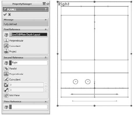
Double-click the Plate Layout sketch, and change the 5.836 inch dimension to 6 inches. Change the 7.244 inch dimension to 7 inches. Make sure the model rebuilds, and watch the individual parts update. Figure 16.28 shows these dimensions for reference.


You will need to do more to finish this tooling die than is covered in this tutorial. The point is to give you some experience using the in-context features that are used with a layout sketch technique.
Although in-context functions are powerful and seductive, you should use them sparingly. In particular, be careful about file management issues such as renaming parts and assemblies. The best approach is to use SolidWorks Explorer or the Save As command with both the parts and assemblies open.
In-context techniques, including the Layout feature, are the pinnacle of true parametric practice and enable you to take the concepts of design intent and design for change to an entirely new level.