
CHAPTER 16
HYBRID PROPELLANTS ROCKET PROPULSION1
Rocket propulsion bipropellant concepts in which one component propellant is stored in the liquid phase and the other as a solid are called hybrid propulsion systems or hybrid rocket engines (there is no universally accepted designation). See Fig. 1–6. Hybrid propulsion is of considerable interest to commercial rocket endeavors primarily for space applications. The main advantages of hybrids are: (1) more safety and ruggedness than conventional chemical propulsion systems—vehicles using hybrid propellants may survive unharmed effects of bullet impacts, fires under the vehicle, inadvertent droppings, and of explosions from adjacent munitions or other rockets; (2) start–stop–restart capabilities; (3) relative simplicity compared to liquids which may translate into low overall system cost; (4) higher specific impulse than solid rocket motors and higher density‐specific impulse (see Eq. 7–3) than many common liquid bipropellant engines; and (5) capability to smoothly change thrust on demand over wide ranges. Even though hybrids have many unique features of their own, they do benefit from developments in liquid and solid rockets. Early hybrid motors were produced for target drones and for one small tactical missile. Experimental hybrid motors in sizes between 2 and 250,000 lbf thrust have been developed and ground tested. A few of medium‐sized and small hybrid motors have flown in experimental vehicles. However, as of 2015 none of the larger systems have been designated for production applications. Several different manned suborbital space vehicles have flown with a hybrid propulsion system, as described later in this chapter; these vehicles are launched at altitude (typically 40,000 feet) from a carrier airplane.
Among the disadvantages of hybrid systems are: (1) mixture ratio and hence specific impulse may vary during “steady flow operation” (as well as during throttling) of the nonsolid component; (2) relatively complicated solid geometries are needed with significant and unavoidable fuel residues (slivers) that reduce the mass fraction and may vary unpredictably with random throttling; (3) prone to large‐amplitude, low‐frequency pressure fluctuations (termed chugging); and (4) present descriptions are incomplete, both for solid‐fuel regression rates and for large hybrid systems motor‐scaling effects (resulting in part from their relatively complicated internal grain design configurations). While cracks in the solid component of the hybrid may not be as catastrophic as those in solid motors, total surface area does influence propellant release, and exposed burning areas can change unpredictably during rocket operation (in some of the more complicated designs).
There are presently three distinct configurations of hybrid propulsion systems (Ref. 16–1). By far the most common arrangement, termed the classical or typical configuration, has the fuel in the solid phase and the oxidizer stored as a liquid, and many such arrangements have been experimentally evaluated. The inverse or reverse configuration has the oxidizer as a solid and the fuel in liquid form; comparatively little work has been done on this arrangement. A third one, called the mixed hybrid configuration, includes a small amount of solid oxidizer implanted with the solid fuel, and the fuel‐rich mixture is then burned with additional liquid oxidizer injected either in an afterburner chamber, or simultaneously at the head and end of the grain cavity. This last configuration results from attempts to enhance fuel regression rates and thus increase thrust and chamber pressure (Ref. 16–2). Increased regression rates can also be obtained in the classical configuration with metallized fuel added to the grain. Designs with special chambers upstream and downstream of the solid component region are common with all three configurations. Figure 16–1 shows a proposed classical configuration design consisting of liquid‐oxygen burning hydroxyl‐terminated‐polybutadiene (HTPB) solid fuel originally intended for Space Shuttle lift‐off booster type of applications. The oxidizer can be either a noncryogenic (storable) or a cryogenic liquid depending on application and required specific impulse. For this hybrid application, the oxidizer is injected into a precombustion or vaporization chamber upstream of the primary fuel region. The fuel grain cavity contains numerous axial combustion ports that generate fuel vapor that then reacts with the flowing oxidizer. An aftermixing chamber is provided to ensure that all fuel and oxidizer are essentially completely burned before entering the nozzle.

Figure 16–1 Depiction of a hybrid rocket preliminary concept aimed at boosting a large space vehicle. It has an inert solid fuel grain, pressurized liquid oxygen feed system, and can be throttled. Multiple ports are required to achieve the substantial fuel surface necessary for high flow rates.
16.1 APPLICATIONS AND PROPELLANTS
Hybrid propulsion units are well suited to applications or missions requiring throttling, command shutdown and restart, and long‐duration missions requiring storable propellants associated with infrastructure nontoxic operations (manufacturing and launch) that benefit from non‐self‐deflagrating propulsion systems. Such applications might include primary boost propulsion for space launch vehicles, upper stage propulsion, and satellite maneuvering thrusters. Hybrids have been used to boost winged suborbital manned spaceships.
Many early hybrid rocket motor developments involved target missiles and low‐cost small tactical missile applications (Refs. 16–3 and 16–4). Other development efforts focused on high‐energy upper‐stage motors. In one program (Ref. 16–3), a hybrid motor was developed for high‐performance upper‐stage applications with design requirements that included a nominal thrust level of 22,240 N and an 8:1 throttling range; here oxygen difluoride was selected as the oxidizer with a lithium hydride/polybutadiene fuel grain (both highly toxic). In recent years development efforts have concentrated on prototypes for space launch applications.
A more practical, although lower energy, upper‐stage hybrid propellant system uses 90 to 95% or “high‐test” hydrogen peroxide oxidizer combined with HTPB fuel. Hydrogen peroxide (Ref. 16–5) is considered storable for time periods typical of upper‐stage missions (to mission completion on the order of several months) and is relatively inexpensive. In solid rocket motors, HTPB is used as the binder to consolidate aluminum fuel with an ammonium perchlorate oxidizer matrix. In hybrids, HTPB becomes the entire fuel constituent. HTPB is low cost, processes easily, and will not self‐deflagrate under any known conditions.
A common propellant combination for large hybrid booster applications has been liquid oxygen (LOX) oxidizer with HTPB fuel. Liquid oxygen is a widely used cryogenic oxidizer in the space launch industry; it is relatively safe and delivers high performance at relatively low cost. This hybrid propellant combination produces a nontoxic, reasonably smoke‐free exhaust and is favored for future booster applications because it is chemically and performance‐wise equivalent to LOX–kerosene bipropellant systems. In general, metallized solid fuels may increase performance, but beryllium is very toxic, boron is hard to ignite, lithium has a low heat of combustion, and aluminum oxides often increase the molecular mass of the combustion products often beyond the temperature gain. Work with hydrides and slurries containing these metals (to offset their intrinsic disadvantages) remains in its research stages. On the other hand, hydrogen peroxide (H2O2) and HAN (hydroxyl ammonium nitrate) have proven desirable themochemical properties, non‐toxic exhausts and attractive density‐specific impulses (Ref. 16–5). Their regression rates and combustion efficiencies are only comparable to those obtained using LOX, but they have storage advantages and comparable degrees of “greenness.”
Hybrid propellants may benefit from the addition of powdered aluminum to the fuel for some applications where a smoky or intensely radiative exhaust is no detriment. This addition increases the combustion temperature, reduces the stoichiometric mixture ratio, and increases fuel density as well as overall density‐specific impulse. Although density‐specific impulse (ρfIs) is increased, addition of aluminum to the fuel may reduce the actual specific impulse. Figure 16–2 illustrates theoretical vacuum‐specific impulse levels (calculated at 1000 psia chamber pressure and a 10:1 nozzle expansion area ratio) for a variety of cryogenic and storable oxidizers used in conjunction with HTPB fuel. Table 16–1 tabulates the heat of formation for HTPB reacted with various oxidizers.

Figure 16–2 Theoretical vacuum‐specific impulse of selected oxidizers reacted with hydroxyl‐terminated polybutadiene fuel. The Is of the O2/HTPB propellant is comparable to that of a LOX/kerosene bipropellant engine. IRFNA is red fuming nitric acid.
Table 16–1 Thermochemical Properties of Selected Oxidizers Reacted with HTPB Fuel
| Oxidizer | Type | Boiling Point (°C) | Density (g/cm3) | ΔfHa (kcal/mol) |
| O2 | Cryogenic | −183 | 1.149 | −3.1 |
| O3 | Cryogenic | −112 | 1.614 | +30.9 |
| N2O | Cryogenic | −88 | 1.226 | +15.5 |
| N2O4 | Storable | +21 | 1.449 | +2.3 |
| IRFNAb | Storable | +80 to +120 | 1.583 | −41.0 |
| H2O2 | Storable | +150 | 1.463 | −44.8 |
a ΔfH is the heat of formation at standard conditions as defined in Chapter 5.
b Inhibited red fuming nitric acid.
A suborbital sounding rocket was successfully launched in 2002 by Lockheed Martin using a large hybrid rocket motor. The American Rocket Company (AMROC) before its demise tested many hybrid motors ranging from 100 to 250,000 lbf in thrust. In 1998, SpaceDev (Ref. 16–6) obtained the technical rights, proprietary data, and patents produced by AMROC. A smaller commercial version of the Space Shuttle has been made by Scaled Composites with a hybrid propulsion system (developed by SpaceDev) which, in a well‐publicized accomplishment, won the Ansari X‐Prize when it's SpaceShipOne (see Fig. 16–3) reached space in 2004 with two suborbital manned flights. In 1999, a consortium of aerospace companies also tested several 250,000‐lbf thrust LOX/HTPB hybrid prototypes as a candidate strap‐on booster for space launch vehicles (see Ref. 16–7). In these motors, polycyclopentadiene (PCPD) was added to the HTPB fuel to increase fuel density by about 10% over HTPB alone. The motors were designed to operate for 80 sec at a LOX flow rate of 600 lbm/sec with a maximum chamber pressure of 900 psi. Figure 16–4 illustrates a cross section of one motor configuration. Test results indicated that additional work is necessary to develop large hybrid motor configurations that exhibit stable combustion throughout the motor burn, and for a better understanding of fuel regression‐rate scale‐up factors.
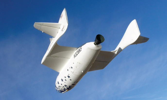
Figure 16–3 SpaceShipOne gliding down for landing. This air ship uses a hybrid propulsion system to produce its main thrust. The propellant is N2O‐HTPB.
(Photo by scaled composites. SpaceShipOne is a Paul G. Allen Project © Mojave Aerospace Ventures, LLC.)

Figure 16–4 Simplified depiction of an experimental 250,000 lbf thrust, hybrid booster with a vaporization chamber, aft mixing chamber and two different solid fuel grains. The vaporization chamber fins and flow deflector are designed to promote flame holding in combustion ports. The fuel ingredient PCPD is polycyclopentadaine.
Hybrid fuel grains are commonly ignited by providing a source of heat, which initiates gasification of the solid fuel grain at the head end of the motor. Subsequent initiation of oxidizer flow provides the required flame spreading to fully ignite the rocket motor. Ignition is typically accomplished by injection of a hypergolic fluid combination into the motor combustion chamber. Using the motor described in Fig. 16–4 as an example, a mixture of triethyl aluminum (TEA) and triethyl borane (TEB) is injected into the vaporization chamber. This TEA–TEB mixture ignites spontaneously on contact with air or with fuel in the combustion chamber, vaporizing fuel in the dome region. Subsequent injection of liquid oxygen completes motor ignition. TEA–TEB mixtures are currently used for motor ignition in the Atlas and Delta commercial launch vehicles. References 16–8 and 16–9 provide descriptions of solid fuels that will ignite spontaneously at ambient conditions when sprayed with specific oxidizers other than LOX. Small hybrid rocket motors, such as those used in laboratory environments with gaseous oxygen, can be electrically ignited by passing current through a resistor (such as steel wool) placed in the combustion port, or by use of separate propane or hydrogen ignition systems.
16.2 INTERIOR HYBRID MOTOR BALLISTICS
As the fuel grain in the classical hybrid configuration contains no oxidizer, combustion processes occur only in the gaseous phase and hence fuel surface regression rates are markedly different from those of a solid rocket motor. Because the solid fuel must vaporize before combustion, fuel surface regression is intrinsically related to the coupling of combustion port fluid dynamics and the heat transfer to the fuel grain surface. The primary combustion region is known to be contained within a relatively narrow flame zone located within the boundary layer region that develops and grows over the fuel grain surface (Ref. 16–10). Heat is transferred to fuel grain surfaces by convection and radiation. Because the study of hybrids is largely empirical, it is well understood that any given motor characteristics will strongly depend on the propellant system and on the scale and configuration of the combustion chamber being described.
Figure 16–5 shows a simplified model of the hybrid combustion process for a nonmetallized (or low radiation) fuel system. Fuel vaporized as a result of flame zone heating flows away from the surface toward the flame region, while oxidizer convects from the free stream (core flow) to the flame zone by turbulent diffusion. The flame establishes itself at a location within the boundary layer determined solely by the stoichiometry under which combustion can occur. The thickness of this flame zone is governed primarily by the rate at which oxidation reactions occur. Such rates are largely dependent on local pressures and typically follow an exponential dependence on temperature.

Figure 16–5 Simplified model of a diffusion‐controlled hybrid combustion process, illustrating a flame zone embedded within the fuel boundary layer. T is temperature and u is velocity, the subscript e denotes external to boundary layer.
Factors beyond pressure and gas temperature affecting the development of the fuel‐grain boundary layer, and hence fuel regression characteristics, include grain composition, combustion port oxidizer mass flow rate, and combustion port length and cross‐sectional area. Existing boundary layers are more complex and more robust than those introduced in Chapter 3 inside supersonic nozzles. Heat transfer relationships between the gas and the solid phase strongly depend on whether the boundary layer is laminar or turbulent. In a typical hybrid using oxygen, the Reynolds number per unit axial length is on the order of 1 to 2×10⁵ per inch of grain length for flux levels between 0.3 and 0.67 lbm/sec‐in.2 Thus, fully turbulent boundary layers govern convective heat transfer (to nonmetallized fuel grains) and empirical equations must often be utilized. Figure 16–6 summarizes overall behavior of many oxidizer/solid‐fuel combinations. As shown in this figure, there are three distinct regimes as a function of increasing mass–flow–velocity in the free stream (![]() , total or oxidizer mass flow rate). At the low mass flux regime, radiative heat transfer phenomena are manifest in the form of pressure and diameter effects on the optical transmissivity of the propellant gas (Refs. 16–11 and 16–12), effects which may also arise from any metal loading present; at the “melting limit” the fuel grain may melt, char, or undergo subsurface decomposition (Ref. 16–11). The intermediate range represents fully turbulent heat and mass transfer, and the regression rate dependence on G0.8 is consistent with the traditional turbulent diffusion results. At the high mass flow rates effects from gas‐phase kinetics on chemical reactions are apparent and a different type of pressure dependence appears (the “flooding limit” results when the flame is extinguished by the high oxidizer flow rates, and depends on pressure and chemical reactivity of the propellants). Because solid fuel regression rates are a function of many parameters, the reader is encouraged to consult the relevant literature before using any of the correlations included in this chapter. A thorough summary of classical hybrid regression rate equations is given in Ref. 16–11, which clearly exemplifies the complexity of this subject.
, total or oxidizer mass flow rate). At the low mass flux regime, radiative heat transfer phenomena are manifest in the form of pressure and diameter effects on the optical transmissivity of the propellant gas (Refs. 16–11 and 16–12), effects which may also arise from any metal loading present; at the “melting limit” the fuel grain may melt, char, or undergo subsurface decomposition (Ref. 16–11). The intermediate range represents fully turbulent heat and mass transfer, and the regression rate dependence on G0.8 is consistent with the traditional turbulent diffusion results. At the high mass flow rates effects from gas‐phase kinetics on chemical reactions are apparent and a different type of pressure dependence appears (the “flooding limit” results when the flame is extinguished by the high oxidizer flow rates, and depends on pressure and chemical reactivity of the propellants). Because solid fuel regression rates are a function of many parameters, the reader is encouraged to consult the relevant literature before using any of the correlations included in this chapter. A thorough summary of classical hybrid regression rate equations is given in Ref. 16–11, which clearly exemplifies the complexity of this subject.

Figure 16–6 Hybrid regimes of regression rate dependencies.
(Adapted from Ref. 16–11.)
With nonmetallized fuel grains, at the pressures and flux levels of interest for propulsion applications, heat transfer by convection is considered to be much larger than that transferred by gas‐phase radiation or radiation from soot particles in the flow. As a result the basic characteristics of fuel grain regression may be explored via analyses of convective heat transfer in a turbulent boundary layer. Thus, for the central regime of Fig. 16–6, the following equation may be used for the fuel regression rate, ![]() :
:
Here, G is the total free‐stream propellant mass velocity (oxidizer and fuel flow per unit area) at any given axial combustion port location x, ρf is the solid‐phase fuel density, μ is the combustion gas viscosity, and β is a nondimensional fuel mass flux parameter reflecting fuel vaporization and evaluated at the fuel surface. All dimensions in Eq. 16–1 need to be in the English Engineering system of units to match the numerical constant. The parameter β is frequently called the blowing coefficient and can be shown to also represent a nondimensional enthalpy difference between the fuel surface and flame zone (i.e., Δh/hv where hv is the heat of gasification). Equation 16–1 indicates that hybrid fuel regression rates in this nonradiative regime are strongly dependent on G and rather weakly dependent on both axial location (x) and fuel blowing characteristics (β). It should also be noted that these regression rates are not explicitly dependent on chamber pressure. This is not the case for the other regimes shown in Fig. 16–6 because metallized hybrid fuel systems may exhibit pronounced pressure dependences (see Ref. 16–13).
As propellants move down the combustion port, the gasified fuel being added in the port passage increases the total mass flux. In locations operating at low mixture ratios, this fuel mass increase may be of the same order as the oxidizer mass flow initially entering the port. Given the weak dependence of regression rate on x in Eq. 16–1, it would be expected that fuel regression would increase along the flow direction with increases of G. While this generally turns out to be the case, fuel regression has been observed to both increase and decrease with increasing x, depending on the details of the rocket motor configuration. In practice, axial fuel regression characteristics are strongly influenced by the method of oxidizer injection and by existing precombustion/vaporization chamber design characteristics. Some general trends observed with increasing x are: total mass flux increases, boundary layer thickness growths, flame‐standoff distance from the surface increases, combustion port average gas density increases, and oxidizer concentration decreases.
Since the blowing coefficient β is not only an aerodynamic parameter but also a thermochemical parameter, and since its x dependence is of the same order, Eq. 16–1 is often simplified for purposes of preliminary engineering design by lumping the effects of x, β, fuel density, and gas viscosity into one parameter, usually given the symbol a. Moreover, in practice, some deviations from the theoretical 0.8‐power of the mass velocity exponent are often noted. The resulting simplified form of Eq. 16–1 is therefore written as
Here, Go is the oxidizer mass velocity (i.e., the oxidizer mass flow rate divided by the combustion port cross‐sectional area). Also, the parameters a and n are empirically fitted constants. In the central range of Fig. 16–6, ![]() has been observed to have values between 0.05 and 0.2 in./sec and n has been observed to range between 0.4 and 0.7.
has been observed to have values between 0.05 and 0.2 in./sec and n has been observed to range between 0.4 and 0.7.
In the low mass flux end of Fig. 16–6 or when metallized fuels are utilized, radiation heat transfer cannot be neglected. Recent studies of this region have yielded accurate but elaborate empirical fits, which are reported in Ref. 16–11. In essence, a radiation heat flux term must be added to the convective heat arriving at the fuel surface, and this results in modifications to the turbulent diffusion relations applicable here. A simpler empirical correlation that somewhat represents modifications in this end range behavior (Ref. 16–14) may be written as follows:
where pref and Dref are empirically selected reference pressures and diameters, and the form of ![]() is given by Eq. 16–2 (multiplied by 2.50 to normalize it).
is given by Eq. 16–2 (multiplied by 2.50 to normalize it).
At the high mass flux end, chemical kinetic effects dominate, and here a strong pressure dependence of the form (p1)0.5 is both predicted and observed. A useful empirical fit in the region where heterogeneous reaction kinetics plays a strong role is of the form
where the exponent n varies between 0.3 and 0.4 (lower values than 0.8 from the middle domain), and the exponent m varies between 0.1 and 0.2 reflecting a consistently weak dependence on the axial location (see Ref. 16–11 for details).
Whenever there is deep reliance on empirical information, as in this field, further guidelines are needed before using any given formulation; otherwise, applying these equations must be restricted to their range of experimental observation. Dimensional analysis and similarity theories are designed to generalize experimental results by casting relevant variables in suitable dimensionless forms (e.g., see Eq. 8–20 and Problem 16–2) but the most satisfactory approach is the one where theory and experiment go hand in hand. The interested reader should consult Refs. 16–12 and 16–15.
16.3 PERFORMANCE ANALYSIS AND GRAIN CONFIGURATION
A characteristic operating feature of classical hybrids configurations is that fuel regression rates are usually less than one‐third those for composite solid rocket propellants. It is very difficult to obtain fuel regression rates comparable to burn rates in solid rocket motors. Consequently, practical high‐thrust hybrid motor designs must have multiple perforations (combustion ports) in the fuel grain to produce the relatively large fuel surface area required. The performance of a hybrid rocket motor (defined in terms of delivered specific impulse) depends critically on the degree of flow mixing attained in the combustion chamber. High performance stems from high combustion efficiency, which is a direct function of the thoroughness with which unburned oxidizer mixes with unburned fuel. Downstream of the fuel grain, extra chamber combustion ports can serve to promote higher combustion efficiencies in the turbulent mixing environment of unreacted fuel and oxidizer.
A cross section of a typical high‐thrust hybrid fuel grain is shown in Fig. 16–4. The number of combustion ports required is a motor optimization problem that must account for the desired thrust level, acceptable shifts in mixture ratio during burn, motor length and diameter constraints, and desired oxidizer mass velocity. Hybrid rocket motor designs typically begin with the specification of a desired thrust level and propellant combination. Subsequently, selection of the desired operating oxidizer‐to‐fuel mixture ratio (O/F ratio) determines propellant characteristic velocity. Once the characteristic velocity and mixture ratio are specified, total propellant flow rate and the subsequent split between oxidizer and fuel flow rates necessary to produce the required thrust level can be computed. The necessary fuel flow rates in a hybrid are determined by total fuel surface areas (perimeter and length of the combustion ports) and by fuel regression rates. As will be shown in subsequent sections, fuel regression rates are primarily determined by the oxidizer mass velocity, also called the oxidizer flux which is equal to the mass flow rate of oxidizer in a combustion port divided by the port cross‐sectional area. Thus, fuel flow rates are intrinsically linked to oxidizer flow rates and cannot be independently specified, as in liquid rocket engines.
Much but not all of the technology from liquid and solid propellant rockets can be directly applied to hybrid rockets; the main differences lie in the driving mechanisms for solid component burning and hybrid fuel regression. In solid propellants, the oxidizer and fuel ingredients are well mixed during propellant manufacturing process; combustion occurs as a result of heterogeneous chemical reactions on or very near the surface of the solid propellant; the solid propellant burning rate is controlled by chamber pressure and follows the well‐established burning rate of Eq. 12–5, with empirical coefficients derived experimentally for specific propellant formulations. Since the rate of propellant gasification per unit area in a solid rocket motor (at a given propellant bulk temperature and in the absence of erosive burning) is determined only by chamber pressure, motor thrust is predetermined by the initial propellant grain surface area and grain geometrical characteristics.
In hybrids with metallized fuel grains, radiation from the meta‐ oxide particle cloud in the combustion port contributes a major portion of the total heat flux to the fuel grain. The local regression rate of the fuel is also quite sensitive to the general turbulence level of the combustion port gas flow (Refs. 16–16 and 16–17). Localized combustion gas eddies or recirculation zones adjacent to the fuel surface act to significantly enhance the regression rate in these areas. Hybrid fuel regression rate is considered to be insensitive to fuel grain bulk temperatures over the range in which solid rocket motors may operate (−65 to +165 °F). This is due to the absence of heterogeneous fuel/oxidizer reactions at the fuel surface (in which the reaction rates are temperature dependent) and because, over the above temperature range, any change in heat content of the solid fuel is small compared to the heat necessary to initiate vaporization of the fuel surface.
Selection of fuel ingredients can also have a significant impact on grain regression rates, which are largely a function of the energy required to convert the fuel from solid to vapor phase (hv). This energy is called the heat of gasification and, for polymeric fuels, includes the energy required to break polymer chains (heat of depolymerization) and the heat required to convert the polymer fragments to gaseous phase (heat of vaporization). The term “heat of vaporization” is often used as a catchall phrase to include all decomposition mechanisms in hybrid fuels. In nonmetallized fuels, low heats of gasification tend to produce higher regression rates. In metallized fuels, the addition of ultra‐fine aluminum (UFAl) powder (particle sizes on the order of 0.05 to 0.1 µm) to HTPB has been noted to significantly increase fuel regression rates relative to a pure HTPB baseline (see Ref. 16.18 and Fig. 16–7). Hybrid propellants containing aluminum particles with diameters typical of those used in solid rocket propellants (40 to 400 µm) do not exhibit this effect.

Figure 16–7 Ultra‐fine aluminum (UFAl) powder mixed with HTPB significantly increases the fuel regression rate.
An alternative form of Eq. 16–2, to account for an observed pressure and/or port diameter dependency, is written as
where m has been observed to vary between zero and 0.25 and l between zero and 0.7.
Figure 16–8 illustrates surface regression rate data obtained for the combustion of HTPB fuel grains and gaseous oxygen in rocket motor tests at two different scales. The first data set were obtained by testing fuel grains in a small laboratory‐scale (2‐in. motor diameter with a 0.43‐in. combustion port diameter) rocket at varying gaseous oxygen flux levels. A least‐squares regression analysis, performed to determine the constants in Eq. 16–2, indicates that, at this scale, the following relationship best describes the regression rate characteristics of HTPB as a function of oxygen mass flux (English Engineering units):

Figure 16–8 Regression‐rate decrease with hybrid motor scale (combustion port diameter) increases.
Data obtained with the same propellant system in a larger 11‐in.‐diameter hybrid motor with combustion port diameters ranging between 3 and 6 in. exhibited a relatively stronger dependence on combustion port diameter. Data from this testing was best matched with an expression in the form of Eq. 16–5 (English Engineering units):
Such difference in fuel regression characteristics between the two motor scales illustrates one of the central difficulties in hybrid motor design, that is, that of scaling ballistic performance. Scaling issues in hybrid motors are currently not well understood (in part because of the lack of sufficient valid data for different motor sizes) while the literature abounds with empirical regression‐rate scaling relationships. Computational fluid dynamic approaches that resolve the hybrid flow field and calculate fuel surface heating appear to offer the best hope for analytically evaluating scale effects (Ref. 16–19).
Dynamic Behavior
Dynamic behavior in hybrid propulsion systems is important because, as stated earlier, mixture ratio always varies even during steady‐state oxidizer flow. When mass storage term changes (i.e., the propellant gas that remains to fill the increasing chamber volume as in solid motors, Section 12.1) may be neglected in the combustor cavity, then Eqs. 6–2 and 3–32 apply, namely,
The steady thrust of a hybrid rocket motor can then be expressed as
Changing the thrust or throttling a hybrid motor (in the classical configuration) is achieved by changing the oxidizer flow rate, usually by means of a throttling valve in the oxidizer feed line. The fuel flow is a function of the oxidizer flow, but not necessarily a linear function. For circular port geometries with inner radius R, Eq. 16–2 may be recast as
The mass flow rate of fuel is given by
where Ab is the combustion port surface area and L is the port length. Combining Eqs. 16–10 and 16–11, we obtain the fuel production rate in terms of port radius and oxidizer mass flow rate:
From this expression we note that, for ![]() , the fuel mass flow rate becomes independent of combustion port radius and varies as the square root of oxidizer mass flow rate. For such situation, if the oxidizer flow is reduced to one‐half of its rated value, the fuel flow will be reduced by a factor of 0.707 and the rocket motor thrust, which depends on the total propellant flow
, the fuel mass flow rate becomes independent of combustion port radius and varies as the square root of oxidizer mass flow rate. For such situation, if the oxidizer flow is reduced to one‐half of its rated value, the fuel flow will be reduced by a factor of 0.707 and the rocket motor thrust, which depends on the total propellant flow ![]() , will not vary linearly with the change in oxidizer flow. Usually, as thrust is decreased by reducing oxidizer flow, the mixture ratio
, will not vary linearly with the change in oxidizer flow. Usually, as thrust is decreased by reducing oxidizer flow, the mixture ratio ![]() is also reduced, becoming increasingly fuel rich. In some hybrid motor concepts, a portion of the oxidizer is injected in a mixing chamber downstream of the fuel grain in order to maintain a more constant mixture ratio. However, for most applications, system design may be optimized over the range of mixture ratios encountered with very little degradation of average specific impulse due to throttling.
is also reduced, becoming increasingly fuel rich. In some hybrid motor concepts, a portion of the oxidizer is injected in a mixing chamber downstream of the fuel grain in order to maintain a more constant mixture ratio. However, for most applications, system design may be optimized over the range of mixture ratios encountered with very little degradation of average specific impulse due to throttling.
Equation 16–12 also indicates that, for constant oxidizer flow, fuel flow will increase with increasing port radius if ![]() . For
. For ![]() , fuel flow will decrease with increasing port radius.
, fuel flow will decrease with increasing port radius.
For a fuel grain incorporating N circular combustion ports, Eq. 16–10 can be simply integrated to give combustion port radius, instantaneous fuel flow rate, instantaneous mixture ratio, and total fuel consumed as functions of burn time (t):
- Combustion port radius R(t) as a function of time and oxidizer flow rate:
- Instantaneous fuel flow rate:
- Instantaneous mixture ratio:
- Total fuel consumed:


where L is the fuel grain length, Ri the initial port radius, N the number of combustion ports of radius Ri in the fuel grain, and ![]() and
and ![]() are the total oxidizer and fuel flow rates, respectively. Although the above equations are valid strictly for circular combustion ports, they may be used to give qualitative understanding for hybrid motor behavior applicable to the burning in noncircular ports as well.
are the total oxidizer and fuel flow rates, respectively. Although the above equations are valid strictly for circular combustion ports, they may be used to give qualitative understanding for hybrid motor behavior applicable to the burning in noncircular ports as well.
16.4 DESIGN EXAMPLE
The preliminary design parameters for a large hybrid booster are to be determined as per the following example.
Current practice for preliminary design of hybrid booster concepts is to couple a fuel regression rate model, a grain design model, and booster component design models in a numerical preliminary design procedure. Using numerical optimization algorithms, such a computer model looks for the optimum booster design that maximizes selected optimization variables, such as booster ideal velocity or total impulse, while minimizing booster propellant and inert weight. New manufacturing techniques (additive manufacturing) and green propellants are presently being investigated, see Ref. 16–23.
16.5 COMBUSTION INSTABILITY
Some hybrid combustion processes tend to produce rough pressure‐time characteristics. However, a well‐designed hybrid can typically limit combustion roughness to tolerable levels, approximately 2 to 3% of mean chamber pressure. In any combustion device, pressure fluctuations will tend to organize themselves around the natural acoustic frequencies of the combustion chamber or the oxidizer feed system. While significant combustion pressure oscillations at chamber natural‐mode acoustic frequencies have been observed in numerous hybrid motor tests, such oscillations have not proved to be an insurmountable design problem. When pressure oscillations have occurred in hybrid motors, they have been observed to grow only to a limiting amplitude that depends on factors such as oxidizer feed system and injector characteristics, fuel‐grain geometric characteristics, mean chamber pressure levels, and oxidizer mass velocities. Unbounded growth of pressure oscillations, such as may occur in solid and liquid rocket motors, has not been observed in hybrid motors.
In static tests, hybrid motors appear to exhibit two basic types of instability: oxidizer‐feed‐system induced instability (nonacoustic), and flame holding instability (acoustic). Oxidizer feed system instability is essentially a chugging type as described in Chapter 9 and arises when the feed system is sufficiently pliable or “soft.” In cryogenic systems, this implies a high level of compressibility from sources such as vapor cavities or two‐phase flow in feed lines combined with insufficient isolation from motor combustion processes. Figure 16–10 (a) illustrates feed system induced instability in a 24‐in.‐diameter hybrid rocket motor that operated at a LOX flow rate of 20 lbm/sec with HTPB fuel. This instability is manifested by high‐amplitude, periodic oscillations well below the first longitudinal (1‐L) acoustic mode of the combustor. In this example the oscillation frequency is 7.5 Hz whereas the 1‐L mode frequency is approximately 60 Hz. Stiffening the feed/injection system (e.g., making it more resistant to vibration) can eliminate such oscillation. This is accomplished by increasing the injector pressure drop (thus making propagation of motor pressure disturbances upstream through the feed system more difficult) and eliminating sources of compressibility in the feed system. Chugging‐type instabilities in hybrid motors have proven amenable to analysis in terms of prediction and prevention (Ref. 16–20). For comparison, Fig. 16–10(b) shows a pressure–time trace from the same 24‐in.‐diameter hybrid motor exhibiting under stable combustion while being operated at a LOX flow rate of 40 lbm/sec and at a maximum chamber pressure of 900 psi.

Figure 16–10 (a) Periodic, large‐amplitude, low‐frequency combustion pressure oscillations are an example of oxidizer feed system induced “chug”‐type combustion instability in a 24‐in.‐diameter LOX/HTBP motor. (b) Example of stable combustion in the same 24‐in.‐diameter LOX/HTPB motor, exhibiting an overall combustion roughness level of 1.3%.
Flame‐holding instabilities relevant to hybrid motors were first observed during the development of solid fuel ramjets (Ref. 16–21). A solid fuel ramjet is essentially a hybrid motor operating on atmospheric oxygen available from rammed air. Flame‐holding instabilities in hybrids typically manifest at acoustic frequencies and appear in longitudinal modes. No acoustic instabilities in hybrid motors have been observed in the higher frequency tangential or radial modes that appear in solid rocket motors or in liquid rocket engines. Flame‐holding instabilities arise from inadequate flame stabilization inside boundary layers (Ref. 16–11) and are not associated with feed system flow perturbations. In one flame‐holding instability example, an 11‐in.‐diameter hybrid motor was tested with gaseous oxygen (GOX) oxidizer and HTPB fuel, using an injector producing a conical flow field; here, oxygen flow was initiated through the hybrid motor at a pressure of 90 psi for 2 sec prior to motor ignition; the motor was ignited using a hydrogen torch that continued to operate for approximately 1 sec following motor ignition. During the first second of motor operation, the hydrogen igniter flame stabilized the motor but when the igniter flame was extinguished, the motor became unstable. In this case stable combustion was achieved by changing the flow field within the motor, using an injector producing an axial flow field. Figure 16–11 shows the results, decomposing the pressure versus time signal for this unstable example into its frequency components via fast Fourier transform techniques. The 1‐L (longitudinal) acoustic oscillation mode is clearly visible at around 150 Hz.

Figure 16–11 Frequency‐versus‐amplitude plot at successive time intervals for an 11‐in.‐diameter GOX/HTPB motor test shows pressure oscillations in the motor first longitudinal (1‐L) acoustic mode at 150 Hz due to flame‐holding instability.
It is now apparent that flame‐holding instabilities can be eliminated by several means, all of which act to stabilize combustion in the boundary layers. The first method is to use a “pilot flame” derived from injecting a combustible fluid such as hydrogen or propane to provide sufficient oxidizer preheating at the leading edge region of the boundary layer flame zone. With this technique, motor stability characteristics are relatively insensitive to the nature of the injector flow field. In the example above, the hydrogen torch igniter acted as a pilot during its period of operation. A second method involves changing the injector flow field to ensure that a sufficiently large hot gas recirculation zone is present at the head end of the fuel grain. Such a zone can be created by forcing the upstream flow over a rearward‐facing step or by strong axial injection of oxidizer (see Fig. 16–12). Axial injection in the correct configuration produces a strong counter‐flowing hot gas recirculation zone, similar to that in a rearward‐facing step, at the head end of the diffusion flame (conical injection produces a much smaller and usually ineffective recirculation zone). These techniques produce flow field results very similar to those produced by bluff body flame stabilizers, used in jet engine afterburners and solid fuel ramjets to prevent flame blowoff. The recirculation zone acts to entrain hot gas from the core flow, which provides sufficient oxidizer preheating for the leading edge of the boundary layer diffusion flame to stabilize combustion.

Figure 16–12 (a) Sketch of axial injection into a vaporization chamber of oxidizer that results in a strong hot gas flow recirculation zone at the fuel grain leading edge, producing stable combustion. (b) Conical oxidizer injection may produce a weak or nonexistent hot gas flow recirculation zone at the fuel grain leading edge, resulting in unstable combustion.
Comparison of the average pressure levels in the above‐mentioned instability illustrates an interesting phenomenon. For the same motor operating conditions (oxidizer flow rate, grain geometry and composition, and throat diameter) the average pressure level in the unstable motor is significantly greater than that in the stable motor. This same phenomenon has been noted in solid propellant motors and results from intensification of heat transfer to the fuel surface due to gas convection at the fuel surface oscillating at high frequency. The high heating rate results in the vaporization of more fuel than would otherwise occur in equilibrium conditions, thus producing a higher average chamber pressure.
Despite recent advances in understanding causes of and solutions for combustion instability in hybrid motors, development of a comprehensive, predictive theory of combustion stability remains one of the major challenges in hybrid technology development (see Ref. 16–24).
SYMBOLS
| a | burning or regression rate coefficient (units of a depend on value of oxidizer flux exponent) | variable units |
| Ap | combustion port area | m2 (in.2) |
| As | fuel grain surface area | m2 (in.2) |
| At | nozzle throat area | m2 (ft2) |
| c* | characteristic velocity | m/sec (ft/sec) |
| vacuum thrust coefficient | dimensionless | |
| cp | heat capacity | J/kg‐K (Btu/lbm‐°R) |
| db | fuel grain burn distance | m (in.) |
| Dh | hydraulic diameter (4Ap/P) | m (in.) |
| Dp | combustion port diameter | m (in.) |
| Dt | nozzle throat diameter | m (in.) |
| vacuum thrust | N (lbf) | |
| G | mass velocity | kg/m2‐sec (lbm/ft2‐sec) |
| Go | oxidizer mass velocity | kg/m2‐sec (lbm/ft2‐sec) |
| g0 | acceleration of gravity—conversion factor | m/sec2—32.174 lbm‐ft/lbf‐sec2 |
| h | convective heat transfer coefficient | J/m2‐sec/K (Btu/ft2‐sec/°R) |
| heat of gasification | J/kg (Btu/lbm) | |
| Δh | flame zone–fuel surface enthalpy difference | J/kg (Btu/lbm) |
| Hf | heat of formation | J/kg‐mol (kcal/mol) |
| Is | specific impulse | Sec |
| k | specific heat ratio | dimensionless |
| L | combustion port length | m (in.) |
| propellant flow rate | kg/sec (lbm/sec) | |
| fuel flow rate | kg/sec (lbm/sec) | |
| oxidizer flow rate | kg/sec (lbm/sec) | |
| n, m, l | burning or regression rate pressure exponent | dimensionless |
| P | combustion port perimeter | m (in.) |
| p1 | chamber pressure | MPa (lbf/in.2) |
| R | combustion port radius | m (in.) |
| Ri | initial combustion port radius | m (in.) |
| Re | Reynolds number | dimensionless |
| fuel regression rate | mm/sec (in./sec) | |
| r | oxidizer to fuel mixture ratio | dimensionless |
| T | temperature | °C (°F) |
| t | time | Sec |
| ue | gas free‐stream velocity in axial direction | m/sec (ft/sec) |
| gas velocity normal to fuel surface | m/sec (ft/sec) | |
| x | axial distance from leading edge of fuel grain | m (in.) |
| y | length coordinate normal to fuel surface | m (in.) |
Greek Letters
| α | fuel surface absorptivity | Dimensionless |
| β | boundary layer blowing coefficient | dimensionless |
| μ | gas viscosity | N−sec/m2 (lbf−sec/ft2) |
| ρ1 | combustion chamber gas density | kg/m3 (lbm/in.3) |
| ρe | free stream gas density | kg/m3 (lbm/in.3) |
| ρf | fuel density | kg/m3 (lbm/in.3) |
Subscripts
| e | boundary layer edge conditions | |
| f | fuel | |
| i | initial conditions | |
| o | oxidizer | |
| s | surface conditions | |
| x | axial distance from leading edge of fuel grain | m (in.) |
| ref | reference conditions |
PROBLEMS
- Consider a classical hybrid motor with a solid fuel grain stored in a single cylindrical enclosure. The combustion port radius is R and the length L. Using the fuel burning rate given by Eq. 16–2, namely,
 with
with  :
:
- a What happens to the thrust with time for a constant oxidizer mass flow rate during the burn?
- b What happens to the mixture ratio if the oxidizer rate is decreased?Answers: (a) and (b) decreases.
-
- Write Eq. 16–1 in terms of a Reynolds number based on the free‐stream gas flow and the axial location x. What does this say about the Reynolds number dependence of surface regression rate?
- It is know that the blowing coefficient is itself roughly proportional to x0.2. What additional assumptions might be necessary to transform Eq. 16–1 into 16–2?
- Calculate the ideal density‐specific impulse (in units of kg−sec/m3) for the propellant combination LOX/HTPB at an oxidizer‐to‐fuel ratio of 2.3 at a pressure ratio across the nozzle of 1000/14.7 and an optimum expansion. Use the information in Table 16–2 and a fuel density of 920 kg/m3. Compare your result with the value of LOX/RP‐1 bipropellant listed in Table 5–5.
Answer: kg‐sec/m3
 - Plot the instantaneous mixture ratio given by Eq. 16–15 as a function of the index n and time. Use values of n greater and less than ½ (at
 the time dependence vanishes). In order to focus only on the effects of n, work with the modified variables ψ (related to mixture ratio) and τ (related to time) defined as follows:

- A classical hybrid propulsion system has the following characteristics:
Determine initial and final thrust, specific impulse, propellant masses, and useful propellant.Propellants LOX/HTPB Nominal burn time 20 sec Initial chamber pressure 600 psi Initial mixture ratio 2.0 Initial nozzle exit area ratio 10.0 Fuel grain outside diameter 12 in Grain geometry Single cylinder case bonded Initial HTPB temperature 65 °F
REFERENCES
- 16–1. K. K. Kuo, Chapter 15, “Challenges of Hybrid Rocket Propulsion in the 21st Century,” in M. A. Chiaverini and K. K. Kuo (Eds.), Fundamentals of Hybrid Rocket Combustion and Propulsion, Vol. 218, Progress in Astronautics and Aeronautics, AIAA, Reston, VA, 2007.
- 16–2. R. A. Frederick Jr., J. J. Whitehead, L. R. Knox, and M. D. Moser, “Regression Rates of Mixed Hybrid Propellants,” Journal of Propulsion and Power, Vol. 23, No. 1, Jan.–Feb. 2007.
- 16–3. D. Altman and A. Holzman, “Overview and History of Hybrid Rocket Propulsion,” in M. A. Chiaverini and K. K. Kuo (Eds.), Fundamentals of Hybrid Rocket Combustion and Propulsion, Vol. 218, Progress in Astronautics and Aeronautics, AIAA, Reston, VA, 2007, Chapter 1.
- 16–4. H. R. Lips, “Experimental Investigation of Hybrid Rocket Engines Using Highly Aluminized Fuels,” Journal of Spacecraft and Rockets, Vol. 14, No. 9, Sept. 1977, pp. 539–545.
- 16–5. S. Heister and E. Wernimont, Chapter 11, “Hydrogen Peroxide, Hydroxil Ammonium Nitrate, and Other Storable Oxidizers,” in M. A. Chiaverini and K. K. Kuo (Eds.), Fundamentals of Hybrid Rocket Combustion and Propulsion, Vol. 218, Progress in Astronautics and Aeronautics, AIAA, Reston, VA, 2007.
- 16–6. SpaceDev website: http://www.spacedev.com.
- 16–7. T. A. Boardman, T. M. Abel, S. E. Chaflin, and C. W. Shaeffer, “Design and Test Planning for a 250‐klbf‐Thrust Hybrid Rocket Motor under the Hybrid Demonstration Program,” AIAA Paper 97‐2804, Jul. 1997.
- 16–8. S. R. Jain and G. Rajencran, “Performance Parameters of Some New Hybrid Hypergols,” Journal of Propulsion and Power, Vol. 1, No. 6, Nov.–Dec. 1985, pp. 500–501.
- 16–9. U. C. Durgapal and A. K. Chakrabarti, “Regression Rate Studies of Aniline‐Formaldehyde‐Red Fuming Nitric Acid Hybrid System,” Journal of Spacecraft and Rockets, Vol. 2, No. 6, 1974, pp. 447–448.
- 16–10. G. A. Marxman, “Combustion in the Turbulent Boundary Layer on a Vaporizing Surface,” Tenth Symposium on Combustion, The Combustion Institute, 1965, pp. 1337–1349.
- 16–11. M. A. Chiaverini, Chapter 2, “Review of Solid‐Fuel Regression Rate Behavior in Classical and Nonclassical Hybrid Rocket Motors,” in M. A. Chiaverini and K. K. Kuo (Eds.), Fundamentals of Hybrid Rocket Combustion and Propulsion, Vol. 218, Progress in Astronautics and Aeronautics, AIAA, Reston, VA, 2007.
- 16–12. F. P. Incropera and D. P. DeWitt, Fundamentals of Heat and Mass Transfer, 5th ed., John Wiley & Sons, Hoboken NJ, 2002.
- 16–13. L. D. Smooth and J. C. Price, “Regression Rates of Metallized Hybrid Fuel Systems,” AIAA Journal, Vol. 4, No. 5, September 1965, pp. 910–915.
- 16–14. D. Altman and R. Humble, Chapter 7, “Hybrid Rocket Propulsion Systems,” in R. W. Humble, G. N. Henry, and W. J. Larson, Space Propulsion Analysis and Design, McGraw‐Hill, New York, 1995.
- 16–15. A. Gany, Chapter 12, “Similarity and Scaling Effects in Hybrid Rocket Motors,” in M. A. Chiaverini and K. K. Kuo (Eds.), Fundamentals of Hybrid Rocket Combustion and Propulsion, Vol. 218, Progress in Astronautics and Aeronautics, AIAA, Reston, VA, 2007.
- 16–16. P. A. O. G. Korting, H. F. R. Schoyer, and Y. M. Timnat, “Advanced Hybrid Rocket Motor Experiments,” Acta Astronautica, Vol. 15, No. 2, 1987, pp. 97–104.
- 16–17. W. Waidmann, “Thrust Modulation in Hybrid Rocket Engines,” Journal of Propulsion and Power, Vol. 4, No. 5, Sept.–Oct. 1988, pp. 421–427.
- 16–18. M. A. Chiaverini et al., “Thermal Pyrolysis and Combustion of HTPB‐Based Fuels for Hybrid Rocket Motor Applications,” AIAA paper 96‐2845, Jul. 1996; “M. A. Chiaverini, K. K. Kuo, A. Peretz, and G. C. Harting, Regression‐Rate and Heat‐Transfer Correlations for Hybrid Rocket Combustion, Journal of Propulsion and Power, Vol. 17, No. 1, Jan.–Feb. 2001, pp. 99–110.
- 16–19. V. Sankaran, Chapter 8, “Computational Fluid Dynamics Modeling of Hybrid Rocket Flowfields,” in M. A. Chiaverini and K. K. Kuo (Eds.), Fundamentals of Hybrid Rocket Combustion and Propulsion, Vol. 218, Progress in Astronautics and Aeronautics, AIAA, Reston, VA, 2007.
- 16–20. T. A. Boardman, K. K. Hawkins, R. S. Wasson, and S. E. Claflin, “Non‐Acoustic Feed System Coupled Combustion Instability in Hybrid Rocket Motors,” AIAA Hybrid Rocket Technical Committee Combustion Stability Workshop, 31st Joint Propulsion Conference, 1995.
- 16–21. B. L. Iwanciow, A. L. Holzman, and R. Dunlap, “Combustion Stabilization in a Solid Fuel Ramjet,” 10th JANNAF Combustion Meeting, 1973.
- 16–22. T. A. Boardman, D. H. Brinton, R. L. Carpenter, and T. F. Zoladz, “An Experimental Investigation of Pressure Oscillations and Their Suppression in Subscale Hybrid Rocket Motors,” AIAA Paper 95‐2689, Jul. 1995.
- 16–23. S. A. Whitmore et al., “Survey of Selected Additively Manufactured Propellants for Arc‐Ignition of Hybrid Rockets,” paper AIAA 2015‐4034, Orlando FL, 2015.
- 16–24. A. Karabeyoglu, Chapter 9, “Combustion Instability and Transient Behavior in Hybrid Motors,” in M. A. Chiaverini and K. K. Kuo (Eds.), Fundamentals of Hybrid Rocket Combustion and Propulsion, Vol. 218, Progress in Astronautics and Aeronautics, AIAA, Reston, VA, 2007.