
CHAPTER 15
SOLID ROCKET MOTOR COMPONENTS AND DESIGN
This is the last of four chapters on solid propellant rocket motors. Here, we describe key components such as the motor case, nozzle, and igniter; subsequently we elaborate on the design of these motors. Although thrust vector control mechanisms are also components of many rocket motors, they are described separately in Chapter 18.
15.1 ROCKET MOTOR CASE
Solid propellant rocket motor cases enclose the propellant grain and also serve as highly loaded pressure vessels, often as part of the flight vehicle structure. Case design and fabrication technology has progressed to where efficient and reliable motor cases can now be produced consistently for many solid rocket applications. Problems arise, however, when the established technology is used improperly; incorrect design analysis or understating of requirements may lead to improper materials and process controls, and to omitting necessary nondestructive tests at critical points in the fabrication process. Besides constituting the structural body of the rocket motor including its nozzle and propellant grain, the case frequently serves also as the primary structure of the missile or launch vehicle. Thus, optimizing case designs frequently entail trade‐offs between case design parameters and vehicle design parameters. Often, case design is further influenced by assembly and fabrication requirements.
Table 15–1 lists many types of case loads with their sources; only some of these must be considered at the beginning of case design and they depend on rocket motor application. Additionally, environmental conditions peculiar to each specific motor usage must be carefully considered. Typically, the scrutinized conditions include the following: (1) temperature changes leading to thermal stresses and strains (internal heating, external or aerodynamic heating, and ambient temperature cycling during storage); (2) stress corrosion (moisture/chemical, galvanic, and hydrogen embrittlement); and (3) space environment stressors (vacuum or radiation).
Table 15–1 Rocket Motor Case Loads
| Origin of Load | Type of Load/Stress |
| Internal pressure | Tension biaxial, vibration |
| Axial thrust | Axial, vibration |
| Rocket motor nozzle | Axial, bending, shear, thermal |
| Thrust vector control actuators | Axial, bending, shear |
| Thrust termination equipment | Biaxial, bending |
| Aerodynamic control surfaces or wings mounted to case | Tension, compression, bending, shear, torsion |
| Staging | Bending, shear |
| Flight maneuvering | Axial, bending, shear, torsion |
| Vehicle mass and wind forces on launch pad | Axial, bending, shear |
| Dynamic loads from vehicle oscillations | Axial, bending, shear |
| Start pressure surge | Biaxial tension |
| Ground handling, including lifting | Tension, compression, bending, shear, torsion |
| Ground transport | Tension, compression, shear, vibration |
| Earthquakes (large motors) | Axial, bending, shear |
Three classes of materials have traditionally been used: high‐strength metals (steels, alloys of aluminum or titanium), wound‐filament reinforced plastics, and a combination of these where metal cases have externally wound filaments for extra strength. Table 15–2 compares several typical materials. For filament‐reinforced materials it gives data not only for the composite material, but also for several strong filaments and typical binders. Since the strength‐to‐density ratio is higher for composite materials, they have less inert mass but there are some important disadvantages; filament‐wound cases with a plastic binder are usually superior on a vehicle performance basis. Metal cases combined with external filament‐wound reinforcements and spiral‐wound metal ribbons glued together with plastics have also been successful.
Table 15–2 Physical Properties of Selected Solid Propellant Motor Materials at 20 °C
Source: Data adapted in part from Chapter 4 by Evans and Chapter 7 by Scippa Ref. 12–1.
| Material | Tensile Strength, N/mm2 (103 psi) | Modulus of Elasticity, N/mm2 (106 psi) | Density, g/cm3 (lbm/in.3) | Strength to Density Ratio (1000) |
| Filaments | ||||
| Glass | 1930–3100 | 72,000 | 2.5 | 1040 |
| (280–450) | (10) | (0.090) | ||
| Aramid (Kevlar 49) | 3050–3760 | 124,000 | 1.44 | |
| (370–540) | (18.0) | (0.052) | 2300 | |
| Carbon fiber | 3500–6900 | 230,000–300,000 | 1.53–1.80 | 2800 |
| (500–1000) | (33–43) | (0.055–0.065) | ||
| Binder (by itself) | ||||
| Epoxy | 83 | 2800 | 1.19 | 70 |
| (12) | (0.4) | (0.043) | ||
| Filament‐Reinforced Composite Material | ||||
| Glass | 1030 | 35,000 | 1.94 | 500 |
| (150–170) | (4.6–5.0) | (0.070) | ||
| Kevlar 49 | 1310 | 58,000 | 1.38 | 950 |
| (190) | (8) | (0.050) | ||
| Graphite IM | 2300 | 102,000 | 1.55 | 1400 |
| (250–340) | (14.8) | (0.056) | ||
| Metals | ||||
| Titanium alloy | 1240 | 110,000 | 4.60 | 270 |
| (155–160) | (16) | (0.166) | ||
| Alloy steel (heat treated) | 1400–2000 | 207,000 | 7.84 | 205 |
| (200–280) | (30) | (0.289) | ||
| Aluminum alloy 2024 (heat treated) | 455 | 72,000 | 2.79 | 165 |
| (66) | (10) | (0.101) | ||
The shape of motor cases is usually determined from their grain configuration and/or from geometric vehicle constraints on length or diameter. Case configurations range from long, thin cylinders (length to diameter ratio, L/D, of 10) to spherical or near‐spherical geometries (see Figs. 1–5, 12–1 to 12–4, and 12–17). Spherical shapes provide the lowest case mass per unit of enclosed volume. Because the case is often a key structural element of the vehicle, it has to allow for the mounting of other components. Propellant mass fractions of motors are usually strongly influenced by the mass of the case and they typically range from 0.70 to 0.94. The higher values apply to upper‐stage motors. For small‐diameter motors the mass fraction is lower, because of practical wall thickness constraints and because the ratio of the wall surface area (which varies roughly as the square of the diameter) to chamber volume (which varies roughly as the cube of diameter) is less favorable in small sizes. Minimum case thicknesses always need to be higher than would be determined from simple stress analyses because they have to include two layers of filament strands for fiber composites, and because certain minimum metal thickness' are dictated by manufacturing and handling considerations.
Simplified membrane theory can be used to predict approximate stresses in solid propellant rocket chamber cases; it assumes no bending of the case walls and that all the loads are taken in tension. For a cylinder of radius ![]() and thickness
and thickness ![]() , with chamber pressure
, with chamber pressure ![]() , the longitudinal stress
, the longitudinal stress ![]() is one‐half of the tangential or hoop stress
is one‐half of the tangential or hoop stress ![]() :
:
For a cylindrical case with hemispherical ends, the cylinder walls have to be twice as thick as the walls of the end closures.
Combined stresses should never exceed the working stresses of the wall material. As a rocket motor begins to operate, an increasing internal pressure ![]() causes case growth in both the longitudinal and circumferential directions, and these deformations must be considered in designing supports for the rocket motor and/or propellant grain. Let
causes case growth in both the longitudinal and circumferential directions, and these deformations must be considered in designing supports for the rocket motor and/or propellant grain. Let ![]() be Young's modulus of elasticity,
be Young's modulus of elasticity, ![]() be Poisson's ratio (0.3 for steel), and
be Poisson's ratio (0.3 for steel), and ![]() be the wall thickness; then, the growth in length
be the wall thickness; then, the growth in length ![]() and in diameter
and in diameter ![]() due to pressure can be expressed as
due to pressure can be expressed as

Details can be found in regular texts on thin shells and membranes. For a hemispherical chamber end, the stress in each of two directions at right angles to each other is equal to the longitudinal stress of a cylinder of identical radius. For ellipsoidal end‐chamber closures, the local stress varies with position along the surface and maximum stresses are larger than that in hemispheres. Radial displacements of a cylinder end are not the same as those for hemispherical or ellipsoidal closures when computed by thin‐shell theory. Thus existing discontinuities may result in some shearing and bending stresses. Similarly, the presence of an igniter boss attachment, or a pressure gauge, or a nozzle can superimpose bending and shear stresses on the simple tension stresses in the case. In these locations it is necessary to locally reinforce or thicken the case wall.
During rocket motor operation, heat transfer from the hot gases causes a continuous rise of temperature at the case walls. This heating is reduced at locations where there is internal thermal insulation. In locations where the propellant in bonded directly to the case walls (or to a thin liner layer, which in turn is bonded to the case walls), there can also be essentially little or no heat transfer to these walls (except for a modest amount just before burnout). When the rocket motor case is also the outer skin in a flying vehicle, for certain speeds and altitudes hot boundary layers develop that produce external heating at the case walls. In order to reduce this external heating, an outer layer of oxidation resistant insulation has successfully been applied for certain atmospheric flight applications.
Heat transfer in solid propellant rocket motors seldom reaches a steady state and local temperatures for all nozzle and case components continuously increase during motor operation. Analyses that result in temperature‐time histories have been useful for determining thicknesses and other thermal insulation component parameters and are also useful for estimating thermal stresses. Finite‐element computer stress analyses are used by motor design companies to determine case design configurations with desirable stress values. Such computations must be done simultaneously with corresponding stress analyses on the grain (since it imposes loads on the case), and with any other coupled thermal analysis that determines thermal stresses and deformations.
Case designs need to provide a means for attaching the case to the vehicle, as well as for attaching nozzles (rarely more than one nozzle) and igniters, together with provisions for loading the grain. Sometimes there are also attached aerodynamic surfaces (fins), sensing instruments, a raceway (external conduit for electrical wires), handling hooks, and thrust vector control actuators with their power supply. For upper stages of ballistic missiles the case structure can also include blow‐out ports or thrust termination devices, as described in Chapter 14. Typical methods for attaching these items include multiple pins (tapered or straight), snap rings, and/or bolts. Gaskets and/or O‐ring seals are needed to prevent gas leaks.
Metal Cases
Metal cases have several advantages compared to filament‐reinforced plastic cases: they are more rugged and will take the considerable rough handling required in many tactical missile applications, are usually ductile and yield before failure, and may be heated to relatively high temperatures (700 to 1000 °C or 1292 to 1832 °F, and higher with refractory metals) thus requiring less insulation. They will not deteriorate significantly with time or weather exposure and are easily adapted to take concentrated loads, if made thicker at a flange or boss. Since a metal case has much higher density and less insulation, it occupies less volume than a fiber‐reinforced plastic case; therefore, for the same external envelope, it may contain somewhat more propellant.
Figure 15–1 shows various sections of a typical large solid rocket motor case made of welded steel pieces. The shape of the case, particularly the length‐to‐diameter ratio in cylindrical cases, influences not only the stresses withstood by the case but the quantity of case material required to enclose a given amount of propellant. For very large and long motors both the propellant grain and the motor case have been made in sections; these case segments are then mechanically attached and sealed to each other at the launch site. The segmented solid rocket booster used in the Space Shuttle is shown in Fig. 15–2 and discussed in Ref. 15–1. Although this rocket motor is now out of production, it represents a good example of a segmented design; other similarly segmented rocket motors are still in use today. For critical seals between segments, a multiple‐O‐ring type of joint is often used as shown in Fig. 15–3 and discussed in Ref. 15–2. Segments are needed when an unsegmented rocket motor would be too large and too heavy to be transported over ordinary roads (i.e., cannot make road turns) or railways (will not go through some tunnels or under some bridges) and/or are too difficult to fabricate.

Figure 15–1 Typical large solid rocket motor case made of welded alloy steel.

Figure 15–2 Simplified diagram of the four segments of the historic Space Shuttle solid rocket booster motor. Details of the thrust vector actuating mechanism or the ignition system are not shown.
Courtesy of NASA and Orbital ATK

Figure 15–3 The joints between segments of the Shuttle Solid Rocket Booster (SRB) were redesigned after its dramatic failure. The improvements were not only in a third O‐ring, the mechanical joint, and its locking mechanism, but also featured a redesign of the insulation between propellant segments. See Ref. 15–3.
Courtesy of NASA
Small metal cases for tactical missile rocket motors can be extruded or forged (and subsequently machined), or made in three pieces as shown in Fig. 12–4. Such motor case is designed for loading a freestanding grain where the case, nozzle, and blast tube are sealed by O‐rings (see Chapter 6 of Ref. 15–4 and Chapter 7 of Ref. 15–5). Since mission velocities for most tactical missiles are relatively low (100 to 1500 m/sec), their propellant mass fractions are also relatively low (0.5 to 0.8) and the percentage of inert motor mass is high. Safety factors for tactical missile cases are often higher to allow for rough handling and cumulative damage. The emphasis in selecting motor cases (and other hardware components) for tactical missiles is therefore not on highest performance (lowest inert motor mass), but on reliability, long life, low cost, safety, ruggedness, and/or survivability.
High‐strength alloy steels have been the most common case metals, but others, like alloys of aluminum, titanium, and nickel, have also been used. Table 15–2 gives a comparison of rocket motor case material properties. Extensive knowledge exists today for designing and fabricating motor cases with low‐alloy steels with strength levels of over 240,000 psi.
Maraging steels have strengths up to about 300,000 psi in combination with high fracture toughness. The term maraging is derived from the fact that these alloys exist as relative soft low‐carbon martensites in their annealed condition and attain higher strengths from aging at relatively low temperatures.
Stress‐corrosion cracking in certain metals presents unique problems that may result in spontaneous failure without any visual evidence of an impending catastrophe. Emphasis given to lightweight thin metal cases aggravates stress corrosion and crack propagation that often starts from a flaw in the metal, with failures occurring at a stress levels below the documented yield strength of the original metal.
Wound‐Filament‐Reinforced Plastic Cases
Filament‐reinforced cases use continuous filaments of strong fibers wound in precise patterns and bonded together with a plastic. Their principal advantage is lower weight. Most plastics soften when they are heated above about 180 °C or 355 °F; they need inserts or reinforcements to allow fastening or assembly of other components and to accept concentrated loads. Thermal expansion of reinforced plastics is often higher than that of metal and the thermal conductivity is much lower, causing higher temperature gradients. References 15‐4 and 15‐5 explain the design and winding of these composite cases, and Ref. 15–6 discusses their damage tolerance.
Typical fiber materials are, ordered by increasing strength, glass, aramids (Kevlar) and carbon, as listed in Table 15–2. Typically, for the same load the inert mass of a case made of carbon fiber is about 50% of one made with glass fibers and around 67% that of a case mass made with Kevlar fibers.
Individual fibers are strong only in tension (2400 to 6800 MPa or 350,000 to 1,000,000 psi). Fibers are held in place by plastic binders of relatively low density; this prevents fibers from slipping and thus weakening in shear or bending. In a filament‐wound composite case (with existing tension, hoop, and bending stresses) filaments are not always oriented along the direction of maximum stress and the materials may include low‐strength plastics; therefore, the strength of composites may be a factor of 3 to 5 less than the strength of the filament itself. The traditional plastic binder is a thermosetting epoxy material, which limits maximum temperatures to between 100 and 180 °C or about 212 and 355 °F. Although resins with higher temperature limits are available (295 °C or 563 °F), their fiber adhesion has not been sufficiently strong. Typical safety factors used (in deterministic structural analysis) are for failure to occur at 1.4 to 1.6 times the maximum operating stresses, and proof testing is done up to 1.15 to 1.25 times operating pressures.
A typical case design is shown schematically in Fig. 15–4. The forward and aft ends and the cylindrical portion are wound on a preform or mold which already contains the forward and aft rings. The direction in which the bands are laid onto the mold and the tension that is applied to the bands is critical in obtaining proper case designs. Curing is done in an oven and may be done under pressure to assure high density and minimum voids in the composite material. The preform is then removed. One way is to use sand with a water‐soluble binder for the preform; after curing the case, the preform is washed out with water. Since filament‐wound case walls can be porous, they must be sealed. The liner between the case and the grain can be the only seal that prevents hot gases from seeping through the case walls. Scratches, dents, and moisture absorption degrade case strengths.

Figure 15–4 Simplified half‐section of a typical design of a filament‐wound composite material case. Elastomeric adhesive seals are shown in black. The outer layer reinforces the cylinder portion and provides attachment skirts. The thickness of the inner case increases at smaller diameter.
In some designs insulator material is placed on the preform before winding and the case is cured simultaneously with the insulator, as described in Ref. 15–7. In another design the propellant grain with its forward and aft closures is used as the preform. A liner is applied to this grain, then an insulator, and the high‐strength fibers of the case are wound in layers directly over the insulated live propellant. Here, curing has to be done at relatively low temperatures so that the propellant will not be adversely affected. This process works well with extruded cylindrical grains. There are also cylindrical cases made of steel with an overwrap layer of filament‐wound composite material, as described in Ref. 15–8.
Allowable stresses are usually determined from tensile tests with roving or band clusters and rupture tests on subscale composite cases made by an essentially identical filament winding process. Some companies further reduce the allowable strength value to account for degradation due to moisture, manufacturing imperfections, or nonuniform densities.
In a wound motor case the filaments must be oriented in the direction of the principal stress and must be proportioned in number to the magnitude of that stress. Compromise occurs around parts needed for nozzles, igniters, and so on, where orientations are kept as close to the ideal as practicable. Filaments are customarily clustered in yarns, rovings, or bands, as indicated in Fig. 15–5. By using two or more winding angles (i.e., helicals and circumferentials) and by calculating the proportion of filaments in each direction, a balanced stress structure may be achieved. The ideal balance is for each fiber in each direction to carry an equal tension load. Realistically, filaments supported by an epoxy resin must also absorb stress compressions, bending loads, cross‐laminar shears, and interlaminar shears. Even though the latter stresses are small compared to the tensile ones, each must be analyzed since they can lead to case failure before any filament fails in tension. In a proper design, failure should occur only when filaments reach their ultimate tensile strength, rather than from stresses in other directions. Figure 18‐5 shows the cross section, made of ablative materials, of a Kevlar filament motor case and detail of its flexible nozzle.

Figure 15–5 Filament winding terminology (each sketch is drawn to a different scale).
15.2 NOZZLES1
Supersonic nozzles provide for the efficient expansion of hot chamber gases and have to withstand the severe environment of high heat transfer and erosion. Advances in material technology presently allow substantial mass reductions and performance improvements. Nozzles range in size from 0.05 in. throat diameter to about 90 in. (to date only experimental) , with operating durations of a fraction of a second (small thrusts) to several minutes (large thrusts) (see Chapters 2 and 3 of Ref. 15–4 and Chapter 6 in Ref. 15–5).
Classification
Nozzles for solid propellant rocket motors can be classified into five categories as listed below and as shown in Fig. 15–6.
- Fixed nozzle. Simple and frequently used in tactical weapon propulsion systems for short‐range air‐, ground‐, and sea‐launched missiles, also as strap‐on propulsion for space launch vehicles such as Atlas and Delta, and in spacecraft rocket motors for orbital transfer. Typical throat diameters are between 0.25 and 5 in. for most tactical missile nozzles, but some are larger.
- Movable nozzle. Provides thrust vector control to a flight vehicle. As explained in Chapter 18, one movable nozzle can provide pitch and yaw control and two are needed for roll control. Movable nozzles are typically submerged and use a flexible seal or a ball‐and‐socket joint with two actuators 90° apart to achieve omniaxial motion. Movable nozzles are primarily used in long‐range strategic propulsion ground‐ and sea‐launched systems (typical throat diameters are 7 to 15 in. for the first stage and 4 to 5 in. for the third stage) and in large space launch boosters. Titan's boost rocket motor and Ariane's V solid rocket booster have throat diameters in the 30‐ to about 90‐in. range.
- Submerged nozzles. A significant portion of the nozzle structure is submerged within the combustion chamber or case, as shown in Figs. 15–2 and 15–6 b, c. Submerging the nozzle reduces the overall motor length somewhat, which in turn reduces the vehicle length and its inert mass. It is important for length‐limited applications such as silo‐ and submarine‐launched strategic missiles as well as their upper stages, and for space propulsion systems. Within a fixed motor length, it also allows an increase of propellant mass inside the case. The splitline between fixed and movable sections is more favorably located than with external subsonic splitline movable nozzles (see Ref. 15–9). Reference 15–10 describes the sloshing of trapped molten aluminum oxide that can accumulate in the groove around a submerged nozzle; this accumulation is undesirable, but can be minimized by proper design.
- Extendible nozzle. Commonly referred to as an extendible exit cone (EEC), although it is not always exactly conical. It is used on strategic missile propulsion upper‐stage systems and upper stages on space launch vehicles to maximize motor‐delivered specific impulse. As shown in Fig. 12‐3, this nozzle has a fixed low‐area‐ratio section, which is enlarged to a higher area ratio by adding one or more nozzle cone extension pieces. The extended nozzle improves specific impulse by doubling or tripling the initial expansion ratio, thereby significantly increasing the nozzle thrust coefficient. This system thus allows very high expansion ratio nozzles to be packaged in a relatively short length, thereby reducing vehicle inert mass. The nozzle cone extensions reside in their retracted position during the boost phase of the flight and are moved into place before their rocket motor is started but after separation from the lower stage. Typically, electromechanical ball screw actuators deploy exit cone extensions.
- Blast‐tube‐mounted nozzle. These are used with tactical air‐ and ground‐launched missiles. The blast tube allows the rocket motor's center of gravity (CG) to be close to or ahead of the vehicle CG. This limits the CG travel during motor burn and makes flight stabilization much easier. See Fig. 12‐4.

Figure 15–6 Simplified diagrams of five common nozzle configurations. Here all are shown with a simple conical nozzle, but actual nozzle exits may curve.
As stated in Chapter 12 nozzle throat areas often enlarge slightly during hot firing. An enlargement of more than 10% is usually considered unacceptable. With slight enlargements of the throat area, both the chamber pressure and the specific impulse will slightly decrease. When single value for specific impulse applicable during their entire operation is used in rocket motor specifications it is named the effective specific impulse.
Design and Construction
Almost all solid rocket motor nozzles are cooled by heat absorption in ablative materials. In general, construction of a rocket nozzle features steel or aluminum shells (or housings) designed to carry structural loads (where motor operating pressures and nozzle TVC actuator loads are usually the biggest), and composite ablative insulators (with or without liners) which are bonded to the cases or to the housings. These ablative liners are designed to insulate metal housings, provide the internal aerodynamic contour necessary for efficient combustion gas expansion to generate thrust, and ablate and char in a controlled and predictable manner in order to prevent heat buildups that could substantially weaken the structural housings or the bonding materials. Solid rocket motor nozzles are designed to ensure that the thickness of ablative liners is sufficient to maintain the liner‐to‐housing adhesive bond line below temperatures that would degrade the adhesive structural properties during rocket motor operation. Nozzle designs are detailed in Figs. 1–5, 12–1 to 12–4, and 15–7.
The construction of nozzles ranges from simple, single‐piece nonmovable graphite nozzles to complex multipiece nozzles capable of controlling the direction of the thrust vector. The simpler, smaller nozzles are typically of applications with low chamber pressure, short durations (perhaps less than 10 sec), low area ratios, and/or low thrust. Two typical small, simple built‐up nozzles are shown in Fig. 15–7. Complex nozzles are necessary to meet more difficult design requirements such as providing thrust vector control, operating at higher chamber pressures (and thus at higher heat transfer rates) and/or higher altitudes (large nozzle expansion ratios), producing very high thrust levels, and surviving longer motor burn durations (above 30 sec).

Figure 15–7 Half‐section sketches for two nozzle designs for small solid propellant rocket motors that employ ablative heat sink wall pieces and graphite throat inserts resistant to high temperatures, erosion, and oxidation. The pyrolytic washers or disks are so oriented that their high conductivity direction is perpendicular to the nozzle axis.
Figures 15–8 and 15–9 illustrate design features of a large and relatively complex solid rocket motor with thrust vector control. It was used as the Reusable Solid Motor rocket (RSRM) booster of the Space Shuttle Launch Vehicle, which was retired in 2011. It is typical of other large flexible nozzles. The two RSRMs provided 71.4% of the lift‐off thrust of the Space Shuttle launch vehicle shown in Figs. 1–14 and 15–2. The nozzle was designed to provide structural and thermal safety margins during the Shuttle booster's 2‐min burn time and consisted of nine carbon‐cloth phenolic ablative liners bonded to six steel and aluminum housings. The housings were bolted together to form the structure of the nozzle. A flexible bearing (described further in Chapter 18), made of thin rubber sheets vulcanized to spherically shaped steel shims, enabled the nozzle to vector omni‐axially up to 8 degrees from centerline to provide thrust vector control. Since these metal housings were recovered and reused after each flight, an exit cone severance system (a circumferential linear shaped charge) was used to cut off a major section of the aft exit cone just below the aft exit cone aluminum housing to minimize splashdown loading on the remaining components. NASA's new first‐stage boosters (segmented solid propellant rocket motors) are being patterned after the Space Shuttle's SRM design.

Figure 15–8 External quarter section view of nozzle configuration of the historic Space Shuttle reusable solid rocket motor (RSRM).
Courtesy of Orbital ATK

Figure 15–9 Section through movable nozzle shown in Fig. 15–8 with component identification.
Courtesy of Orbital ATK
From a performance perspective, any nozzle should efficiently expand the gases originating from the motor's combustion chamber to produce thrust. Simple nozzles with noncontoured conical exit cones can be designed using the basic thermodynamic relationships presented in Chapter 3 to establish the throat area, nozzle half angle, and expansion ratio. More complex contoured (bell‐shaped) nozzles are used to reduce divergence losses, improve the specific impulse, and reduce nozzle length and mass. Section 3.4 gives data on designing bell‐shaped nozzles with optimum wall contours (that avoid shock waves and minimize impact of particulates in the exhaust gas).
Two‐dimensional, two‐phase, reacting‐gas method‐of‐characteristics flow codes are used to analyze gas‐particle flows in nozzles for the determination of optimal nozzle contours and of shortened nozzle lengths that maximize specific impulse while yielding acceptable erosion characteristics. Such codes provide results for all identified specific impulse loss mechanisms (in units of secs), which produce a less than ideal performance. An example is given in Table 15–3.
Table 15–3 Calculated Losses in the Space Shuttle Booster RSRM Nozzle
| Theoretical specific impulse (vacuum conditions) | 278.1 sec |
| Delivered average specific impulse (vacuum conditions) | 268.2 sec |
| Losses (calculated): | (9.9 sec total) |
| Two‐dimensional two‐phase flow (includes divergence angle loss) | 7.4 sec |
| Throat erosion (reduces nozzle area ratio) | 0.9 sec |
| Boundary layer (wall friction) | 0.7 sec |
| Submergence (flow turning) | 0.7 sec |
| Finite rate chemistry (chemical equilibrium) | 0.2 sec |
| Impingement (of Al2O3 particles on nozzle wall) | 0.0 sec |
| Shock (if turnback angle is too high or nozzle length too low) | 0.0 sec |
| Combustion efficiency (incomplete burning) | 0.0 sec |
Figure 15–10 illustrates amounts of carbon cloth phenolic liner removed by chemical reactions and by particle impingement erosion, the liner char depth, and gas temperature and pressure at selected locations in the RSRM nozzle. Erosion on the nose cap (1.73 in.) is high primarily as a result of impingement by ![]() particles traveling down the motor bore. The mechanical impact of these particles removes charred liner material. In contrast, the radial throat erosion of 1.07 in. results primarily from the carbon liner material reacting chemically with oxidizing species in the combustion gas flow at the region of greatest heat transfer. At the throat location, impingement erosion is low because any
particles traveling down the motor bore. The mechanical impact of these particles removes charred liner material. In contrast, the radial throat erosion of 1.07 in. results primarily from the carbon liner material reacting chemically with oxidizing species in the combustion gas flow at the region of greatest heat transfer. At the throat location, impingement erosion is low because any ![]() particles present are traveling parallel to the nozzle surface.
particles present are traveling parallel to the nozzle surface.

Figure 15–10 Erosion measurements and char depth data of the carbon fiber phenolic material of the nozzle of the Space Shuttle Reusable Solid Rocket Motor.
Courtesy of Orbital ATK
The often used acronym ITE means integral throat/entrance and refers to a single‐piece nozzle throat insert that also includes a part of the converging entry section. ITE nozzle inserts can be seen in Figs. 1–5, 12–1, 12–3, and 12–4. Most ITEs are made from carbon‐carbon (either 3 or 4 directionally reinforced). The introduction of ITEs has improved reliability and simplified designs (see Ref. 15–22).
As already stated, nozzle throat erosion causes throat diameters to enlarge during operation and is one problem encountered in nozzle design. Usually, a throat area increase larger than about 10% is considered unacceptable for most applications, since it causes a significant reduction in thrust and chamber pressure. Erosion occurs not only at the throat region (typically, at 0.01 to 0.25 mm/sec or 0.004 to 0.010 in./sec), but also at the sections immediately upstream and downstream of it, as shown in Fig. 15–10. Nozzle assemblies typically lose 3 to 12% of their initial inert mass during operation. Erosion is caused by complex interactions between the high‐temperature, high‐velocity gas flow, the chemically aggressive species in the gas, and the mechanical abrasion by small particles. Carbon in nozzle materials reacts with hot species like ![]() ,
, ![]() ,
, ![]() , or
, or ![]() becoming oxidized; the cumulative concentration of these species is an indication of the likely erosion. Tables 5–6 and 5–7 give chemical concentrations for the exhaust species from aluminized propellants. Fuel‐rich propellants (which contain little free
becoming oxidized; the cumulative concentration of these species is an indication of the likely erosion. Tables 5–6 and 5–7 give chemical concentrations for the exhaust species from aluminized propellants. Fuel‐rich propellants (which contain little free ![]() or
or ![]() ) and propellants where some of the gaseous oxygen is removed by aluminum oxidation show fewer erosive tendencies. Uneven erosion in a nozzle causes thrust misalignment. Some tactical designs use a particular grain design that burns very progressively but counter this with a high erosion‐rate material to control the maximum system pressure.
) and propellants where some of the gaseous oxygen is removed by aluminum oxidation show fewer erosive tendencies. Uneven erosion in a nozzle causes thrust misalignment. Some tactical designs use a particular grain design that burns very progressively but counter this with a high erosion‐rate material to control the maximum system pressure.
For bell‐shaped nozzles finding optimum nozzle wall contours requires analysis (computer codes using the method of characteristics are mentioned in Section 3.4) to determine wall contours, which effectively turn the gas to near axial flow without introducing strong shock waves. Results given in Section 3.4 are for gaseous exhaust jets (without entrained solid particles), as may occur with liquids or double‐base solid propellants. Figure 3‐13 illustrates key parameters, which describe such bell shaped nozzles. The initial angle ![]() (angle through which supersonic flow is turned immediately downstream of the nozzle throat) is typically 30 to 50° and the exit angle
(angle through which supersonic flow is turned immediately downstream of the nozzle throat) is typically 30 to 50° and the exit angle ![]() is 10 to 15°. Such bell‐shaped contour allows a 1 to 2% increase in specific impulse, when compared with an equivalent conical nozzle exit having a 15° half angle. For some applications, designers have used a parabolic curve or a circular arc without performance penalties.
is 10 to 15°. Such bell‐shaped contour allows a 1 to 2% increase in specific impulse, when compared with an equivalent conical nozzle exit having a 15° half angle. For some applications, designers have used a parabolic curve or a circular arc without performance penalties.
With solid particles in the exhaust gas bell‐shaped nozzles (designed for a purely gaseous exhaust) quickly erode, particularly at the nozzle exit region where a diverging flow is turned back to a near axial direction. With the insulation eroded, the nozzle exit metal housing quickly burns out. All solid composite propellants have some amount of small solids (mostly ![]() ) in their exhaust. A solution for not losing excessive nozzle insulation materials is to go to a smaller value of the initial angle
) in their exhaust. A solution for not losing excessive nozzle insulation materials is to go to a smaller value of the initial angle ![]() (20 to 32°) on a gentler bell‐shaped contour. Compared to a 15° conical nozzle, the specific impulse gain of such contour is no more than 0.7%. In general, nozzle throat inlet contours are not critical and can be based on any hyperbolic curve that uniformly accelerates the combustion gas flow to sonic velocity at the throat. In the supersonic region the task is more complicated, see Section 3.4. for details.
(20 to 32°) on a gentler bell‐shaped contour. Compared to a 15° conical nozzle, the specific impulse gain of such contour is no more than 0.7%. In general, nozzle throat inlet contours are not critical and can be based on any hyperbolic curve that uniformly accelerates the combustion gas flow to sonic velocity at the throat. In the supersonic region the task is more complicated, see Section 3.4. for details.
Heat Absorption and Nozzle Materials
Since solid rocket motors do not reach thermal equilibrium, the temperature of all components exposed to heat flow increases continuously during operation. In proper thermal designs, critical locations only reach their maximum allowable temperature a short time after the rocket motor stops operation. Nozzle components rely on their heat‐absorbing capacity (high specific heat and high energy required for material decomposition) and slow heat transfer (good insulation with low thermal conductivity) to withstand the stresses and strains imposed by thermal gradients and loads. The maximum allowable temperature for motor materials is taken as just below the temperature at which excessive degradation occurs (e.g., the material loses strength, melts, becomes too soft, cracks, pyrolyses, unglues, or oxidizes too rapidly). Operating durations are thus affected by nozzle design and by the amount of heat‐absorbing and insulating material present. Stated in a different way, one principal design objective here is to arrive at a nozzle with just sufficient heat‐absorbing‐material and insulation so that its structures and joints will do the job for the duration of the application under all likely operating conditions, while complying with mandated margins or factors of safety.
Selection and application of proper materials is the key to successful designs of solid rocket nozzles. Table 15–4 groups various typical nozzle materials according to their usage. High‐temperature exhausts from solid rockets present an unusually severe environment for nozzle materials, especially when metalized propellants are employed.
Table 15–4 Typical Motor Nozzle Materials and Their Functions
| Function | Material | Remarks |
| Structure and pressure container (housing) | Aluminum | Limited to 515 °C (959 °F) |
| Low‐carbon steel, high‐strength steels, and special alloys | Good between 625 and 1200 °C (1157 and 2192 °F), depending on material; rigid and strong | |
| Heat sink and heat‐resistant material at inlet and throat section; severe thermal environment and high‐velocity gas with erosion |
Carbon‐carbon Carbon or Kevlar fiber cloth with phenolic or plastic resins |
Three‐ or four‐directional interwoven filaments, strong, expensive, limited to 3300 °C (5972 °F) |
| Molded graphite | Used with large throats | |
| Tungsten, molybdenum | For low chamber temperatures and low pressures only; low cost | |
| Heavy, expensive, subject to cracking; resist erosion. Rarely used in current designs | ||
| Insulator (behind heat sink or flame barrier); not exposed to flowing gas | Ablative plastics, with fillers of silica or Kevlar, phenolic resins | Want low conductivity, good adhesion, ruggedness, erosion resistance; can be filament wound or impregnated cloth layup with subsequent machining |
| Flame barrier (exposed to hot low‐velocity gas) | Ablative plastics (same as insulators but with less filler and tough rubber matrix) | Lower cost than carbon–carbon; better erosion resistance than many insulators |
| Carbon, or silica fibers with phenolic resin | Cloth or ribbon layups; woven and compressed, glued to housing | |
| Carbon–carbon | Higher temperature than others, three‐directional weave or layup | |
| Nozzle exit cone | Ablative plastic, self‐supporting or with metal or structural plastic structure | Heavy, limited duration; cloth or woven ribbon layups, glued to housing |
| Refractory metal (niobium alloy, Cb‐103, rarely tantalum or molybdenum) | Section near nozzle exit radiation cooled. Strong, needs coating for oxidation resistance; can be thin but heavy | |
| Carbon–carbon, needs gas seal | Radiation cooled, higher allowable temperature than metals; two‐ or three‐directional weave, strong, often porous |
About 80 years ago nozzles were manufactured from a single piece of molded polycrystalline graphite and some were supported by metal housing structures. They eroded easily, but were low in cost. We still use them today for short duration, low chamber pressure, low altitude flight applications with low thrust, such as in certain tactical missiles. For more severe conditions a throat insert or ITE is placed into the graphite piece; this insert is a denser, better grade of graphite; later pyrolytic graphite washers and fiber‐reinforced carbon materials came into use. Figure 15–7 shows a set of non‐isotropic pyrolytic graphite washer in the throat insert of small nozzles (they are not used now). For a period of time tungsten inserts were used; they had very good erosion resistance, but were heavy and their melting point was eventually exceeded as higher motor pressures and hotter propellants came into use. The introduction of high‐strength carbon fibers in a carbon matrix has been a major advance in high‐temperature materials. For small and medium‐sized nozzles, ITE pieces have been made of carbon–carbon, the present abbreviation for carbon fibers in a carbon matrix (see Ref. 15–12). The orientation of the fibers can be two‐directional (2D) or three‐directional (3D), as described below. Some properties of these materials are listed in Tables 15–4 and 15–5. For large nozzles the then existing technology did not allow the fabrication of large 3D carbon–carbon ITE pieces, so layups of carbon fiber (or silicon fiber) cloth in a phenolic matrix were used. An example of a self‐supporting ablative exit cone is the Naxeco‐phenolic structure used in the first stage of the Vega launch vehicle (Ref. 15–13).
Table 15–5 Comparison of Properties of Molded and Pyrolytic Graphite, Carbon–Carbon, Carbon Cloth, and Silica Cloth Phenolic
| ATJ Modern Graphite | Pyrolytic Graphite | Three‐Directional Carbon Fibers in a Carbon Matrix | Carbon Cloth Phenolic | Silica Cloth Phenolic | |
| Density (lbm/in.3) | 0.0556 | 0.079 | 0.062–0.072 | 0.053 | 0.062 |
| Thermal expansion (in./in.‐°F) | 0.005–0.007 | 0.00144 (warp) | 1 − 9 × 10⁻⁶ | 8.02 × 10⁻⁶ | 7.6 × 10⁻⁶ |
| 0.0432 (fill) | |||||
| Thermal conductivity (Btu/in.‐sec/°F) at room temperature | 1.2 × 10⁻³ | 4.9 × 10⁻⁵ (warp)a | 2 to 21 × 10−5 (warp)a | 2.2 × 10⁻³ (warp)a | 1.11 × 10⁻³ (warp)a |
| 1.5 × 10⁻³ | 4.2 × 10⁻⁵ (fill)a | 8 to 50 × 10−5 (fill)a | |||
| Modulus of elasticity (psi) at room temperature | 1.5 × 10⁶ (warp)a | 4.5 × 10⁶ (warp)2 | 35 to 80 × 106 | 2.86 × 10⁻⁶ (warp)a | 3.17 × 10⁻⁶ (warp)a |
| 1.2 × 10⁶ (fill)a | 1.5 × 10⁶ (fill)a | 2.91 × 10⁻⁶ (fill)a | 2.86 × 10⁻⁶(fill)a | ||
| Shear modulus (psi) | — | 0.2 × 10⁶ (warp)a | — | 0.81 × 10⁶ | 0.80 × 10⁶ |
| 2.7 × 10⁶ (fill)a | |||||
| Erosion rate (typical)b (in./sec) | 0.004–0.006 | 0.001–0.002 | 0.0015–0.012 | 0.005–0.010 | 0.010–0.020 |
a Warp is in direction of principal fibers. Fill is at right angles to warp.
b Surface wear rates at which a test article recedes under agreed upon operating conditions—used for comparison only.
Regions immediately downstream of the throat have less heat transfer, less erosion, and lower temperatures than the throat, and less expensive materials are usually satisfactory here. This includes various grades of graphite, or ablative materials, strong high‐temperature fibers (carbon or silica) in a matrix of phenolic or epoxy resins, which are described later in this section. Figure 18‐5 shows a movable nozzle with multilayer insulators behind the graphite nozzle pieces directly exposed to heat. These insulators (between the very hot throat piece and housing) limit the heat transfer and prevent excessive housing temperatures.
In the diverging exit section the heat transfer and temperatures are even lower and similar but less capable ordinary materials can be used there. This segment can be built integral with the nozzle throat (as it is in most small nozzles), or it can be a separate one‐ or two‐piece subassembly, which is then fastened to the smaller diameter throat segment. Ablative materials without oriented fibers as in cloth or ribbons, but with short fibers or insulating ceramic particles, can be utilized. For large area ratios (upper stages and space transfer vehicles), the nozzle will often protrude beyond the vehicle's boattail surface. This allows for efficient radiation cooling since any exposed exit cone can radiate directly to space. High‐temperature metals (niobium, titanium, stainless steel, or a thin carbon–carbon shell) have been used for radiation cooling in some upper‐stage or spacecraft exit cone applications. Since such cooled nozzle sections can quickly reach thermal equilibrium, their duration can be unlimited.
The housing or structural support of the nozzle uses the same material as the metal case, such as steel or aluminum. Housings are never allowed to become very hot. Some of the simpler, smaller nozzles (with one, two, or three pieces of mostly graphite) do not have a separate housing structure, but use the ITE for the structure.
Estimates of nozzle internal temperatures and temperature distributions with time can be made using two‐dimensional finite element software for transient heat transfer analyses. These are similar in principle to the transient heat transfer method described in Section 8.5 where some results are shown in Fig. 8‐20. After firing, nozzles cool by conducting heat from hotter inner parts outer sections. Sometimes these outer pieces will end up exceeding their temperature limit and suffer damage. Structural analyses (of stresses and strains) of key nozzle components are highly interdependent with heat transfer analyses, which determine the component temperatures. Design must also allow for thermal growth and for differential expansion of adjacent parts.
Typical materials used for ITEs or nozzle throat inserts are listed in Table 15–5. These materials are exposed to the most severe heat transfer conditions and undergo high thermal stresses and temperatures. Their physical properties are often anisotropic, that is, vary with the orientation or direction of the crystal structure or of reinforcing fibers. Polycrystalline graphites are extruded or molded units. Different grades with different densities and capabilities are available. As already mentioned, they are used extensively for simple nozzles and for ITE parts. Pyrolytic graphite is strongly anisotropic and has excellent conductivity in one preferred direction. A nozzle using pyrolytic graphite is shown in Fig. 15–7. It is fabricated by depositing graphite crystals on a substrate in a furnace containing decomposing methane gas. While pyrolytic graphite use is declining, it is still installed in current rocket motors of older design.
Carbon–carbon materials are made from carefully oriented sets of carbon fibers (woven, knitted, threaded, needled, or laid up in patterns) in a carbon matrix. Two‐directional (2D) materials have fibers in two directions, 3D have fibers oriented in three directions (usually at right angle to each other), and 4D has fibers oriented in one of two ways, often called “tetrahedral” and “hexagonal” (Ref. 15‐14). In the tetrahedral construction, the carbon bundles are the same diameter in all four directions represented by the four diagonals of a cube. In the hexagonal construction, three of the four directions of reinforcement are in a plane perpendicular to the axial direction. The three directions of yarn bundles in the perpendicular plane are at 60° to each other and are usually smaller in diameter. Highly densified materials are superior in high heat transfer regions, such as the throat. Multidirectional fiber reinforcements allow them to better withstand the high thermal stresses introduced by the steep temperature gradients within the component. There are two methods in use for matrix deposition: chemical vapor deposition (CVD) and liquid impregnation followed by further pyrolyzation. Carbon‐carbon densification is discussed in Ref. 15–9.
The French (Herakles) Naxeco Sepcarb carbon‐carbon and the Naxeco 3‐D reinforced phenolic materials are presently in production and have flown in Vega launches. Carbon‐silicon carbide and refractory metal nozzle components have reached production in the last decade.
Ablative Materials
These commonly used materials in rocket motors nozzles are also used in some insulators. They are usually made from a composite material with high‐temperature organic or inorganic high‐strength fibers, namely, high silica glass, aramids (Kevlar), or carbon fibers, impregnated with organic plastic materials such as phenolic or epoxy resins. The fibers may be individual strands or bands (applied in a geometric pattern on a winding machine), or come as a woven cloth or ribbon, all impregnated with resin.
Ablation may result from a combination of surface melting, sublimation, charring, decomposition in depth, and from film cooling. As shown in Fig. 15–11, progressive layers of ablative material undergo an endothermic degradation, that is, physical and chemical changes occur that absorb heat. While some ablative material evaporates (and some types also have a viscous liquid phase), enough charred and porous solid material should remain on and below the surface to preserve the basic geometry and surface integrity. Upon rocket start, ablative materials act as a thermal heat sink, but their poor conductivity causes their surface temperature to rise rapidly. At temperatures of 650 to 800 K some of resins start to decompose endothermically into a porous carbonaceous char and into pyrolysed gases. As the char depth increases, these gases undergo an endothermic cracking process as they percolate through the char in a counterflow direction to the heat flux. These gases then form an artificial fuel‐rich, protective, relatively cool but flimsy, boundary layer over the char.

Figure 15–11 Zones in an ablative material during rocket operation with two sets of fibers (seen as multiple lines) at 45° to the flow.
Since char is almost all carbon and can withstand 3500 K or 6000 R, porous char layers allow the original surface to be maintained (but with a rough surface texture) and provides geometric integrity. However, the char's carbon may be oxidized by certain combustion gas species in which case there is a slow regression of the charred surface. Char is structurally weak and can be damaged or abraded by direct impingement of solid particles from the flowing gas. Ablative material construction is used for some or all parts of the chambers and/or nozzles shown in Figs. 1–5, 6–9a, 12–1 to 12–4, and 15–10.
Ablative parts are formed either by high‐pressure molding (˜55 to 69 MPa or 8000 to 10,000 psi at 149 °C or 300 °F) or by tapewrapping on a shaped mandrel followed by either hydroclaving, typically at 1000 psi and about 300 °F, or by autoclaving at about 250 psi and 330 °F. Tapewrapping has been a common method of forming in very large nozzles. The wrapping procedure normally includes heating a shaped mandrel (∼54 °C or 130 °F), heating the tape and resin (66 to 121°C or 150 to 250 °F), pressurizing the tape of fiber material and the injected resin in place while rolling (∼35,000 N/m or 200 lbf/in. per inch of width), and maintaining the proper rolling speed, tape tension, wrap orientation, and resin flow rate. Experience has shown that the as‐wrapped density is an important indicator of procedural acceptability, with the desired criterion being near 90% of the autoclaved density. Resin content usually ranges between 25 and 35%, depending on the fabric‐reinforcing material and the particular resin and its filler material. Normally, the mechanical properties of the cured ablative material, and also the durability of the material during rocket operation, correlate closely with the cured material density. Within an optimal density range, a low density usually means poor bonding of the reinforcing layers, high porosity, low strength, and high erosion rates.
We note here that in liquid propellant rocket engines ablatives have been used effectively in very small thrust chambers (where there is insufficient regenerative cooling capacity), in pulsing, restartable spacecraft control rocket engines, in the exit region of large nozzle and in variable‐thrust (throttled) rocket engines. Figure 6‐9a shows an ablative nozzle extension for a large liquid propellant rocket engine.
Heat transfer properties of many available ablative and other fiber‐based materials are highly dependent on their design, composition, and construction. Figure 15–12 shows sketches of several common fiber orientation approaches. The orientation of fibrous reinforcements, whether in the form of tape, cloth, filaments, or random short fibers, has a marked impact on the erosion resistance of composite nozzles (Fig. 15–10 shows erosion data). When perpendicular to the gas flow, erosion resistance is the greatest but heat transfer to outboard surrounding materials is also the highest. Good results have been obtained at throat and entrance locations when the fibers are at 40 to 60° relative to the gas flow, as the taped‐wrapped ply at these angles can still provide high erosion resistance. However, at the exit cone, shallower ply angles (0 to 20°) are used as they reduce the heat transfer while simultaneously providing erosion protection and reducing nozzle weight (Ref. 15–14.)
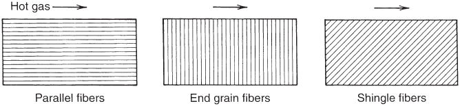
Figure 15–12 Simplified sketches of three different types of fiber‐reinforced ablative materials.
15.3 IGNITER HARDWARE
The process of ignition is described in Section 14.2 and in Section 13.5 some propellants used in igniters are mentioned. In this section we discuss specific igniter types, their locations, and their hardware (see Ref. 15–15).
Since igniter propellant mass is small (often less than 1% of the motor propellant) and burns mostly at low chamber pressure (hence low Is), it has a negligible contribution to the motor's overall total impulse. It is the designer's aim to reduce the igniter propellant mass and the igniter inert hardware mass to a minimum—just big enough to assure ignition of the grain under all operating conditions.
Figure 15–13 shows several proven locations for the igniter. When mounted at the forward end, the gas flow over the propellant surface helps to achieve ignition. With aft mounting there is little gas motion, particularly near the forward end; here, ignition must rely on the temperature, pressure, and heat transfer from the igniter gas. When mounted internally through the nozzle, igniter hardware and supports are discarded shortly after use and there is no inert mass penalty for the igniter case. A unique annular igniter, sleeve‐shaped around a submerged nozzle throat region, has been used successfully with a few of the larger rocket motors. The two basic most common types, pyrotechnic igniters and pyrogen igniters, are discussed below.

Figure 15–13 Simplified diagrams of mounting options for igniters. Grain configurations details are not shown.
Pyrotechnic Igniters
In industrial practice, pyrotechnic igniters are defined as igniters (other than pyrogen‐type igniters) that use solid explosives or energetic propellant‐like chemical formulations (usually small pellets of propellant that provide large burning surfaces and short burning times) as the heat‐producing materials. This definition fits a wide variety of designs, known in the trade as bag and carbon igniters, powder can, plastic case, pellet basket, perforated tube, combustible case, jellyroll, string, or sheet igniters. A common pellet‐basket design is shown in Fig. 15–14, being typical of the pyrotechnic igniters. Ignition of the main charge (in this case pellets consisting of 24% boron–71% potassium perchlorate–5% binder) is accomplished by stages; first, on receipt of an electrical signal the initiator releases the energy of a small amount of sensitive powdered pyrotechnic housed within the initiator, commonly called the squib or the primer charge; next, the booster charge is ignited by heat released from the squib; and finally, the main ignition charge propellants are ignited.

Figure 15–14 Typical pyrotechnic igniter with three different propellant charges that ignite in sequence. Only a few pellets are shown. The larger surface of the pellets gives very short igniter burning times.
A special form of pyrotechnic igniter is the surface‐bonded or grain‐mounted igniter. It has its initiator included within a sandwich of flat sheets; the layer touching the grain has the main pyrotechnic charge. This form of igniter is used with multipulse rocket motors with two or more end‐burning grains. The ignition from the second and successive pulses of these motors presents unusual requirements for available space, compatibility with grain materials, life, and for the resulting pressures and temperatures from booster grain operation. Advantages of the sheet igniter include light weight, low volume, and high heat flux at the grain surface. Any inert material employed (such as wires and electric ceramic insulators) is usually blown out of the motor during ignition and resulting impacts have at times either damaged or plugged the nozzle, particularly if the blown material has not been intentionally broken up into small pieces.
Pyrogen Igniters
A pyrogen igniter is basically a small unit, containing all the elements of a rocket motor, used to ignite a larger rocket motor, see Ref. 15–11, and is not designed to produce thrust. They all consist of one or more nozzle orifices (both sonic and supersonic types) and most use conventional rocket motor grain formulations (sometimes the same as the main propellant grain) and design technology. Heat transfer from the pyrogen gas to the motor grain is largely convective, with hot gases contacting the inner grain surface, in contrast to pyrotechnic igniters that transfer heat by high‐energy radiation. Figures 12–1, 12–2, and 12–20 illustrate rocket motors with a typical pyrogen igniter; in Fig. 18–5 the igniter has three nozzles and a cylindrical grain with high‐burn‐rate propellant. For pyrogen igniters, initiator and booster charge designs are often very similar to those used in pyrotechnic igniters. Reaction products from the main charge impinge on the inside surface of the rocket motor grain, producing motor ignition. Common practice on very large motors is to mount them externally, with the pyrogen igniter pointing its jet up through the large motor nozzle, in which case the igniter becomes a piece of ground‐support equipment.
Two approaches are commonly used to safeguard against rocket motor misfires, or inadvertent ignition; one is to use of the classical safe and arm device and the second is to design safeguards into the initiator. Energy sources causing unintentional ignitions (usually disastrous when they happen) can be (1) static electricity, (2) induced electrical currents from electromagnetic radiation—such as radar, (3) induced electrical currents from ground test equipment, communication apparatus, or nearby electrical circuits in the flight vehicle, and (4) heat, vibration, or shock from motor handling and operations. Functionally, the safe and arm device serves as an electrical switch to keep the igniter circuit grounded and interrupted when not operating; in some designs it also mechanically misaligns or blocks the igniter's gas flow passage so that unwanted ignition is precluded even when the initiator charge may fire. As the device is moved into the arm position, the electric ignition circuit is no longer blocked and an ignition flame can reliably propagate from the igniter's booster and main charges to the propellant surface.
Electric initiators in motor igniters are also called squibs, glow plugs, primers, and headers; they always constitute the initial element in the ignition train and, if properly designed, can act as a safeguard against unintended ignition. Three typical designs of initiators are shown in Fig. 15–15. Both (a) and (b) types form structurally a part of the rocket motor case and generically act as headers. In the integral diaphragm type (a), the initial ignition energy is passed in the form of a shock wave through the diaphragm activating the acceptor charge, with the diaphragm remaining integral. The same principle is also used to transmit shock waves through metal case walls or metal inserts in filament‐wound cases; here, the combustion case would not need to be penetrated and can remain sealed. The header in type (b) resembles a simple glow plug with two high‐resistance bridgewires buried in the initiator propellant charge. The design in type (c) employs a small bridgewire (0.02 to 0.10 mm) of low‐resistance material, usually platinum or gold, that explodes by the application of a high‐voltage discharge.

Figure 15–15 Typical electric initiators; (a) integral diaphragm type; (b) header type with double bridgewire; (c) exploding bridgewire type.
Initiator safeguard aspects appear as a basic design feature in the form of (1) a minimum threshold electrical energy required for activation, (2) voltage‐blockage provisions (usually, air gaps or semiconductors in the electrical circuit), and/or (3) responsiveness only to a specific energy pulse or frequency band. Invariably, such safeguards may compromise to some degree the safety provided by the classical safe and arm device.
A more recent method of initiating igniter action of is to use a laser as an energy source to start the combustion in an initiator charge. Properly designed, there are no problems with induced currents or other inadvertent electrical initiations. The energy from a small neodymium/YAG laser, external to the motor, travels in fiber‐optical glass cables to the pyrotechnic initiator charge (Ref. 15–16). Sometimes an optical window in the case or closure wall allows the initiator charge to be inside the case.
Igniter Analysis and Design
The basics of initiating ignition are common to all designs and applications of pyrotechnic and pyrogen igniters. In general, current analytical models of physical and chemical processes relevant to igniter design (including heat transfer, propellant decomposition, deflagration, flame spreading, and chamber filling) are far from complete and accurate. See Chapter 5 by Hermance and Chapter 6 by Kumar and Kuo in Ref. 14–1, and Ref. 14–15. Analyses and design of igniters, regardless of the type, depend heavily on experimental results. When data on past successes and failures with full‐scale motors is included, the effects of some important parameters have become quite predictable. For example, Fig. 15–16 can be useful in estimating the mass of the igniter main charge for rocket motors of various sizes (i.e., motor free volumes). From these data,
where ![]() is the igniter charge mass in grams and
is the igniter charge mass in grams and ![]() is the motor free volume in cubic inches (the void in the case not occupied by propellant). A larger igniter mass flow means a shorter ignition delay. Ignition time events are shown in Fig.14‐3.
is the motor free volume in cubic inches (the void in the case not occupied by propellant). A larger igniter mass flow means a shorter ignition delay. Ignition time events are shown in Fig.14‐3.

Figure 15–16 Igniter charge or propellant mass versus motor free volume, based on data from various‐sized rocket motors that use AP/Al composite propellant.
Data with permission from Ref. 15–17
15.4 ROCKET MOTOR DESIGN APPROACH
Although there are many common elements in the design of all solid propellant rocket motors, there is as yet no universal, well‐defined set of procedures or design methods. Each application presents different requirements. Individual designers and their organizations have different approaches, background, step sequences, or emphasis. Approaches also vary depending on the amount of available data on design issues, propellants, grains, hardware, materials, with the degree of novelty (many “new” motors are actually modifications of proven existing motors), and/or on available/validated computer software.
The following items are usually part of the preliminary design process: they start with requirements for the flight vehicle and rocket motor, such as those listed in Table 15–6. When the motor under design has enough similarity to proven existing motors, their parameters and flight experiences will be helpful in reducing the design effort and in enhancing confidence in the new design. Selection of propellant and grain configuration are usually made early in the design process (propellant selection is discussed in Chapter 13 and grains in Chapter 12). It is uncommon for any one propellant to satisfy all of the following key requirements, namely, necessary rocket performance (Is), burning rate to suit the desired thrust–time curve, and required strength (maximum stress and strain). A well‐characterized propellant with a proven grain configuration or a well‐tested piece of hardware suitably modified to fit the new application will usually be preferred.
Table 15–6 Typical Requirements and Constraints for Solid Rocket Motors
| Requirement Category | Examples |
| Application | Definition of mission, vehicle and propulsion requirements, flight paths, maneuvers, environment, number required |
| Functional | Total impulse, thrust–time curve, ignition delay, initial motor mass, specific impulse, TVC angles and angular accelerations, propellant fraction, class 1.1 or 1.3, burn time, and tolerances on all of these parameters |
| Interfaces | Attachments to vehicle, fins, TVC system, power supply, instruments, lifting and transport features, grain inspection, control signals, shipping container |
| Operation | Storage, launch, flight environment, temperature limits, transport loads or vibrations, plume characteristics (smoke, toxic gas, radiation), life, reliability, safe and arm device functions, field inspections |
| Structure | Loads and accelerations imposed by thrusting and by vehicle (flight maneuvers), stiffness to resist vehicle oscillations, safety factors |
| Insensitive munitions (military application) | Response to slow and fast cook‐off, bullet impact, sympathetic detonation, shock tests |
| Cost and schedule | Stay within the allocated time and money |
| Deactivation | Method of removing/recycling of propellants, safe disposal of over‐age motors |
| Constraints | Limits on volume, length, or diameter; minimum acceptable performance, maximum cost, maximum inert mass |
| Schedule | Design completion, test articles completion, qualification, delivery |
Analysis is a key ingredient in design; for example, calculations of structural integrity should be undertaken at places where stresses or strains likely exceed those that can be tolerated by the grain, or other key components, at loading limits in the expected range of environmental conditions. An evaluation of thermal growth and thermal stresses is usually performed for every heated component or assembly. An analysis of the nozzle as described in an earlier section of this chapter should be done, particularly if the nozzle is complex or includes thrust vector control. When gas‐flow considerations show that erosive burning that cannot be tolerated is likely to occur during any portion of the burning duration, modifications to the propellant, the nozzle material, or the grain geometry may need to be made. Usually, preliminary evaluation is also done of acoustic resonances in the grain cavity to identify possible combustion instability modes (see Chapter 14). Motor performance calculations that include heat transfer and stresses at critical locations will usually need to be undertaken.
Since there is considerable interdependence and feedback between parameters (propellant formulation, grain geometry/design, stress analysis, thermal analysis, major hardware component designs, and their manufacturing processes), it is difficult to finalize any design without going through several iterations. Data from tests of laboratory samples, subscale motors, and full‐scale motors will strongly influence each step.
Preliminary layout drawings or CAD (computer‐aided design) images of the rocket motor with its key components will have to be made in sufficient detail to provide sizes and reasonably accurate dimensions. For example, preliminary design of the thermal insulation (often from a heat transfer analysis) will provide dimensions for that insulator. Such layouts are then used to estimate volumes, inert masses, propellant masses, propellant mass fraction or center of gravity.
A simplified flow diagram of one particular approach to motor preliminary design and development steps is shown in Fig. 15–17. Not shown in this diagram are many side steps, such as igniter design and tests, liner/insulating selection, thrust vector control design and test, reliability analyses, evaluation of alternative designs, material specifications, inspection/quality control steps, safety provision, special test equipment, special test instrumentation, and others.

Figure 15–17 Diagram of one approach to preliminary design activity sequences and interrelations. Dashed lines indicate feedback paths. Some items listed here only apply to specific types of rocket motors.
If performance requirements are narrow and ambitious, it will be necessary to carefully study cumulative performance tolerances together with various other parameters. For example, practical tolerances may be assigned to the propellant density, nozzle throat diameter (for erosion), burn rate scale factor, initial burning surface area, propellant mass, or pressure exponent. These, in turn, will appear as tolerances in process specifications, specific inspections, dimensional tolerances, or accuracy of propellant ingredient weighing. Cost (see Section 19.4) is always a major factor and a portion of the design effort will be spent looking for lower‐cost materials, simpler manufacturing processes, fewer assembly steps, and/or lower‐cost component designs. For example, tooling for casting, mandrels for case winding and tooling for insulator molding can be expensive. Time needed for completing a design can be shortened when there is effective communication and a cooperative spirit between all design‐individuals (propellant specialists, analysts, customer representatives, manufacturing and test personnel, and/or vendors) concerned with the project. Reference 15–18 deals with some of the uncertainties in a particular booster motor design, and Ref. 15–19 discusses design optimization.
A preliminary project plan is usually formulated simultaneously with the preliminary‐design work. Two decades or more ago the project plan was made after preliminary design was completed. Presently, with a strong emphasis on affordability, personnel working on preliminary designs also have to focus on reducing costs on all components and processes. The project plan reflects such decisions and defines the number of rocket motors and key components to be built, the availability and lead time of critical materials or components, the type and number of tests (including aging or qualification tests); also, project plans identify the manufacturing, inspection, and test facilities to be used, the number and kind of personnel (and when they will be needed), and any special tooling or fixtures. These decisions and these data are needed to make realistic estimates of cost and realistic preliminary schedules. When estimates exceed allowable costs or desired delivery schedules, then some changes are required. For example, there may be changes in the number of units to be built, the number and types of tests, or redesigns for easier, less costly assemblies. However, such changes must not compromise reliability or performance. It is particularly difficult to make good plans and good cost or time estimates when the rocket motor has not been well defined or designed in sufficient detail. Such plans and estimates must therefore be based largely on experience with prior successful similar rocket motors.
Final result of any preliminary design will consist of layout drawings or CAD images of the selected configuration, a prediction of performance, an estimate of rocket motor mass (and, if needed, also the travel of the center of gravity), an identification of the propellant, grain, geometry, insulation, and of several key materials for the hardware components. Any estimate of predicted reliability and motor life needs to be accompanied by supporting data. All information would then be presented for review of the selected preliminary design. This review would be undertaken with a diverse group of rocket motor experts including the vehicle designer, safety engineers, specialists in manufacturing, assembly, or inspection, customer representatives, analysts, and others. Here, the preliminary design team explains why they selected that particular design and how it meets the requirements. With competent reviewers there usually will be suggestions for changes or further improvements. The project plan, preliminary cost estimates, and a preliminary schedule are sometimes included in the design review, but more often these are presented to a separate group of experts, or just to the customer's experts.
After the design review and approval of the selected preliminary design, a detailed or final design of all parts and components and the writing of certain specifications can begin. During manufacture and development testing, further design changes may become necessary to improve the manufacture, reduce cost, or remedy technical problems that have arisen. In many organizations the final, detailed design is again submitted for design review before manufacturing can begin. The new motor will then start its development testing. With the larger, expensive rocket motors that have a lot of heritage from prior proven motors, the development may include a single rocket motor firing with extensive instrumentation. For motors which are to be built in large quantities and for motors with major new features, the development and qualification may involve testing as few as 2 to 4 motors. Final design ends when all detail drawings or CAD images and a final parts list are completed, and specifications for motor testing, certain manufacturing operations, and/or materials/component acceptance have been prepared. Detailed designs are considered complete only after the motor successfully passes all its development and qualification tests and begins production.
PROBLEMS
- In Figs. 14–3 and 14–4, it can be seen that higher case pressures and higher heat transfer rates promote faster ignition. One way to promote this more rapid ignition is for the nozzle to remain plugged until a certain minimum initial pressure has been reached, at which time the nozzle plug will be ejected. Analyze the time saving achieved by such a device, assuming that the igniter gas evolution follows Eqs. 12–3 and 12–5. Under what circumstances is this an effective method? State any relevant assumptions about cavity volume, propellant density, and so on.
- Compare a bare simple cylindrical case with hemispheric ends (ignore nozzle entry or igniter flanges) for an alloy steel metal and two reinforced fiber (glass and carbon)‐wound filament case. Use the properties in Table 15–2 and thin shell structure theory. Given:
Calculate and compare the theoretical propulsion system flight velocity (without payload) in a gravity‐free vacuum for these three cases.Length of cylindrical portion 370 mm Outside cylinder diameter 200 mm Internal pressure 6 MPa Web fraction 0.52 Insulator thickness (average) for metal case 1.2 mm for reinforced plastic case 3.0 mm Volumetric propellant loading 88% Propellant specific gravity 1.80 Specific impulse (actual) 248 sec Nozzle igniter and mounting provisions 0.20 kg - The following data are given for a case that can be made of either alloy steel or fiber‐reinforced plastic.
Stating any assumptions, determine the growth in diameter and length of the case due to pressurization, heating, and the combined growth and interpret the results.Type Metal Reinforced Plastic Material D6aC Organic filament composite (Kevlar) Physical properties See Table 15–2 See Table 15–2 Poisson ratio 0.27 0.38 Coefficient of thermal expansions, m/m‐K × 10− 6 8 45 Outside diameter (m) 0.30 0.30 Length of cylindrical section (m) 0.48 0.48 Hemispherical ends Nozzle flange diameter (m) 0.16 0.16 Average temperature rise of case material during operation (°F) 55 45 - A high‐pressure helium gas tank at 8000 psi maximum storage pressure and 1.5 ft internal diameter is proposed. Use a safety factor of 1.5 on the ultimate strength. The following candidate materials are to be considered:
- Kevlar fibers in an epoxy matrix (see Table 15–2).
- Carbon fibers in an epoxy matrix.
- Heat‐treated welded titanium alloy with an ultimate strength of 150,000 psi and a weight density of 0.165 lbf/in.3
- Determine the dimensions and sea‐level weights of these three tanks and discuss their relative merits. To contain the high‐pressure gas in a composite material that is porous, it is also necessary to include a thin metal inner liner (such as 0.016‐in.‐thick aluminum) to prevent loss of gas; this liner will not really carry structural loads, but its weight and volume need to be considered.
- Make a simple sketch and determine the mass or sea‐level weight of a rocket motor case that is made of alloy steel and is cylindrical with hemispherical ends. State any assumptions you make about the method of attachment of the nozzle assembly and the igniter at the forward end.
Outer case and vehicle diameters 20.0 in. Length of cylinder portion of case 19.30 in. Ultimate tensile strength 172,000 psi Yield strength 151,300 psi Safety factor on ultimate strength 1.65 Safety factor on yield strength 1.40 Nozzle bolt circle diameter 12.0 in. Igniter case diameter (forward end) 3.00 in. Chamber pressure, maximum 1520 psi - Design a solid propellant rocket motor with insulation and liner. Use the AP/Al‐HTPB propellant from Table 12–3 for Orbus 6. The average thrust is 3600 lbf and the average burn time is 25.0 sec. State all the assumptions and rules used in your solution and give your reasons for them. Make simple sketches of a cross section and a half section with overall dimensions (length and diameter), and determine the approximate loaded propellant mass.
- The STAR 27 rocket motor (Fig. 12‐1 and Table 12–3) has an average erosion rate of 0.0011 in./sec. (a) Determine the change in nozzle area, thrust, chamber pressure, burn time, and mass flow at cutoff. (b) Also determine those same parameters for a condition when, somehow, a poor grade of ITE material was used that had three times the usual erosion rate. Comment on the difference and acceptability.Answer: Nozzle area increases by about (a) 5.3% and (b) 14.7% and decrease of chamber pressure at cutoff decreases by approximately the same percentage.
REFERENCES
- 15–1. NASA, National Space Transportation System, Vols. 1 and 2, U.S. Government Printing Office, Washington, DC, Jun. 1988 (Space Shuttle Description).
- 15–2. M. Salita, “Simple Finite Element Analysis Model of O‐Ring Deformation and Activation during Squeeze and Pressurization,” Journal of Propulsion and Power, Vol. 4, No. 6, Nov.–Dec. 1988.
- 15–3. A. J. McDonald and J. R. Hansen, Truths, Lies and O‐Rings, Inside the Space Shuttle Challenger Disaster, Florida University Press, Gainesville FL, 2009.
- 15–4. J. H. Hildreth, Chapter 2, “Advances in Solid Rocket Motor Nozzle Design and Analysis Technology since 1970”; A. Truchot, Chapter 3, “Design and Analysis of Solid Rocket Motor Nozzle”; P. R. Evans, Chapter 4, “Composite Motor Case Design”; A. J. P. Denost, Chapter 5, “Design of Filament Wound Rocket Cases,”; H. Baham and G. P. Thorp, Chapter 6, “Consideration for Designers of Cases for Small Solid Propellant Rocket Motors,”; all in Design Methods in Solid Rocket Motors, AGARD Lecture Series LS 150, Advisory Group for Aerospace Research and Development, NATO, revised 1988.
- 15–5. B. H. Prescott and M. Macocha, Chapter 6, “Nozzle Design”; M. Chase and G. P. Thorp, Chapter 7, “Solid Rocket Motor Case Design”; in G. E. Jensen and D. W. Netzer (Eds.), Vol. 170, Progress in Astronautics and Aeronautics, American Institute of Aeronautics and Astronautics, 1996.
- 15–6. A. de Rouvray, E. Haug, and C. Stavrindis, “Analytical Computations for Damage Tolerance Evaluations of Composite Laminate Structures,” Acta Astronautica, Vol. 15, No. 11, 1987, pp. 921–930.
- 15–7. D. Beziers and J. P. Denost, “Composite Curing: A New Process,” AIAA Paper 89–2868, Jul. 1989.
- 15–8. A. Groves, J. Margetson, and P. Stanley, “Design Nomograms for Metallic Rocket Cases Reinforced with a Visco‐elastic Fiber Over‐wind,” Journal of Spacecraft and Rockets,” Vol. 24, No. 5, Sept.–Oct. 1987, pp. 411–415.
- 15–9. Monograph Space Vehicle Design Criteria (Chemical Propulsion), Solid Rocket Motor Nozzles, NASA‐SP‐8115, Jun. 1975.
- 15–10. S. Boraas, “Modeling Slag Deposition in Space Shuttle Solid Rocket Motor,” Journal of Spacecraft and Rockets, Vol. 21, No. 1, Jan.–Feb. 1984.
- 15–11. L. H. Caveny, R. L. Geisler, R. A. Ellis, and T. L. Moore, “Solid Rocket Enabling Technologies and Milestones in the United States,” Journal of Propulsion and Power, Vol. 19, No. 6, Nov.–Dec. 2003, pp. 1038–1066.
- 15–12. B. H. Broguere, “Carbon/Carbon Nozzle Exit Cones: SEP's Experience and New Developments,” AIAA Paper 97–2674, Jul. 1997.
- 15–13. M. Berdoyes, M. Dauchier, C. Just, “New Ablative Material Offering SRM Nozzle Design Breakthroughs,” AIAA paper 2011‐6052, Jul. 2011. doi: 10.2514/6.2011-6052.
- 15–14. R. A. Ellis, Personal Communication, 2013; R. A. Ellis, J. C. Lee, and F. M. Payne, CSD, USA; and A. Lacombe, M. Lacoste, and P. Joyez, SEP, France, “Development of a Carbon‐Carbon Translating Nozzle Extension for the RL10B‐2 Liquid Rocket Engine.” Presented at 33rdAIAA/ASME/SAE/ASEE Joint Propulsion Conference, Seattle, WA, AIAA paper 97‐2672, Jul. 6–9, 1997.
- 15–15. “Solid Rocket Motor Igniters,” NASA SP–8051, March 1971 (N71–30346).
- 15–16. R. Baunchalk, “High Mass Fraction Booster Demonstration,” AIAA Paper 90–2326, July 1990.
- 15–17. L. LoFiego, Practical Aspects of Igniter Design, Combustion Institute, Western States Section, Menlo Park, CA, 1968 (AD 69–18361).
- 15–18. R. Fabrizi and A. Annovazzi, “Ariane 5 P230 Booster Grain Design and Performance Study,” AIAA Paper 89–2420, Jul. 1989.
- 15–19. A. Truchot, Chapter 11, “Overall Optimization of Solid Rocket Motors,” in Design Methods in Solid Rocket Motors, AGARD Lecture Series LS 150, Advisory Group for Aerospace Research and Development, NATO, revised 1988.