
CHAPTER 10
TURBOPUMPS AND THEIR GAS SUPPLIES
10.1 INTRODUCTION
A turbopump (TP) is a high‐precision, high‐speed rotating machine usually consisting of a gas turbine driving one or two centrifugal pumps. Its purpose is to take propellants from the vehicle's tanks, raise their pressure, and deliver them into suitable piping systems. These pressurized propellants are then fed to one or more thrust chambers, where they are burned forming hot gases. A TP is a unique key component of all larger liquid propellant rocket engines with pumped feed systems. This chapter discusses various common types of TPs, describes major TP components, mentions some of their principal design issues, and outlines one design approach.
A well‐designed TP must deliver the intended propellant flows at the intended pump discharge pressures and mixture ratio, must have an acceptable reliability (e.g., it will not malfunction or fail during the flight duration), and will run at the highest practical energy efficiencies. Furthermore, TPs should not cause any significant vibration (in the engine or entire vehicle) nor should be adversely affected by externally caused vibrations, should function well under all operating conditions (such as different initial propellant temperatures, a range of ambient temperatures, start and stop transients, accelerations in the flight direction and other directions), and have the minimum practical inert TP mass. It is important for pumps not cavitate during operation because cavitation produced bubbles reduce the steady nominal propellant mass flow and cause combustion instabilities. Cavitation is further discussed in Section 10.5. The TP's bearings and seals need to be adequately cooled (by small secondary flows of propellant within the TP assembly) to prevent their overheating and malfunctioning. Since unexpected leaks in the seals and secondary flow passages within a TP cannot be tolerated, there can be no leakages between bipropellants inside the TP, between turbine stages (gas side) or pump stages (liquid side), between a propellant and hot gas, or between propellant or hot gas and the outside atmosphere.
The selection of a specific TP configuration, such as seen later in this chapter, will depend on the propellant combination, the desired flow and pump discharge pressures, the engine cycle, the available pump suction pressures, and the number of units to be built and delivered, among other factors. Available heat‐resistant materials and their maximum working temperatures for the turbine blades or the maximum load capacity of their bearings can limit any design selection. The best TP placement location within a rocket engine represents a compromise between several design considerations. For example, its inlet and outlet flanges should be placed to minimize piping and propellant trapping, holes should be available to allow visual inspection of bearings and turbine blades on reusable engines, mountings should allow for thermal expansion without high stresses, and each design should have a minimum number of TP components—all these will influence the choice of the design configuration. References 10–1 to 10–5 give further information on TP selection and design.
10.2 DESCRIPTIONS OF SEVERAL TURBOPUMPS
Typical TPs can be seen in Figs. 10–1 to 10–3 and 6–9a, and many key components can be identified by their callouts. Most named parts in these figures will be discussed in subsequent paragraphs of this chapter. TPs are also seen as a component of an engine in Figs. 6–1, 6–10, 6–11, and 8–17. A number of different arrangements of key TP components for several common assemblies are shown later in Fig. 10–4. This figure includes different numbers of pumps and turbines, different component arrangements on TP shafts, with or without gear cases, and with or without booster pumps. These will be discussed later in this chapter. Figures 10–1 and 10–2 depict experimental TPs shown here because they clearly identify key components. See Ref. 10–6. Figure 10–1 shows a single‐stage propellant pump; it has a screw‐type axial‐flow inducer impeller ahead of the main impeller and is driven by a single‐stage axial‐flow turbine. The hot combustion gases that drive this turbine are burned in a separate gas generator (or a preburner) at a fuel‐rich mixture ratio that produces gases between 900 and 1200 K; this is sufficiently cool, so that any heated turbine hardware (blades, nozzles, manifolds, or disks) will have sufficient strength without needing forced cooling. Gases are expanded (accelerated) in an annular set of converging–diverging supersonic turbine inlet nozzles, usually cast into the turbine inlet housing. Accelerated gases then enter a set of rotating blades mounted on a wheel or turbine disk. These blades essentially remove the tangential energy of the gas flow. The exhaust gas velocity from the blades is relatively low and its direction is essentially parallel to the shaft. The pump is driven by the turbine through a shaft which is supported by two (experimental) hydrostatic bearings. The propellant enters the pump through an inducer, a special spiral flow impeller where the pressure of the propellant is raised only slightly (perhaps 5 to 10% of the total pressure rise). This should be just enough pressure so that there will be no cavitation as the flow enters the main pump impeller. Most of the kinetic energy given to the flow by the pump impeller is converted into hydrostatic pressure in the diffusers (the diffuser vanes are not clearly visible, since they are inclined) and/or volutes of the pump. Two hydrostatic bearings support the shaft radially. All bearings and shaft seals generate heat as they run so they are cooled and lubricated with small propellant flows, which are supplied from the pump discharge through drilled passages. One bearing (near the pump) is cold and the other is hot, since it is close to the hot turbine. The angular ball bearing accepts axial net loads from the unbalanced hydrodynamic pressures around the shrouded impeller, the inducer, and also from the turbine blades or the turbine disk.

Figure 10–1 Cut‐away view of an experimental turbopump demonstrator with a single‐stage liquid oxygen pump impeller, an inducer impeller, and a single‐stage turbine (one row of blades) on the same shaft.
Courtesy of Aerojet Rocketdyne.

Figure 10–2 Exploded view of an advanced high‐speed, two‐stage experimental liquid hydrogen fuel pump driven by a radial flow turbine.
Used with permission of Aerojet Rocketdyne. Adapted from Ref. 10–7.

Figure 10–3 Section view of early, typical geared turbopump assembly similar to the one used on the RS‐27 engine (Delta I and II launch vehicles) with liquid oxygen and RP‐1 propellants.
Courtesy of Aerojet Rocketdyne.

Figure 10–4 Simplified diagrams of several different component arrangements of turbopumps. F, fuel pump; O, oxidizer pump; T, turbine; G, hot gas; C, shaft coupling; and GC, gear case.
Used with permission from Ref. 10–1.
The (experimental) high‐speed, compact, and light weight liquid hydrogen TP shown in Fig. 10–2 and discussed in Refs. 10–6 and 10–7 was intended to be used with an upper‐stage hydrogen–oxygen rocket engine that would deliver about 50,000 lbf (22.4 kN) thrust. The unique single‐piece titanium rotor (turning nominally at 166,700 rpm) has two machined sets of pump vanes, a machined inducer impeller, a set of machined radial inflow turbine blades, and radial as well as axial hydrostatic bearing surfaces. A small filtered flow of hydrogen lubricates the hydrostatic bearing surfaces. The cast pump housing has internal crossover passages between stages. Its unique radial inflow turbine (3.2 in. dia.) produces about 5900 hp at an efficiency of 78%. The hydrogen pump impellers are only 3.0 in. diameter and produce a pump discharge pressure of about 4500 psi at a fuel flow of 16 lbm/sec and efficiencies of 67%. A pump inlet pressure of about 100 psi is needed to assure cavitation‐free operation. The TP can operate down to about 50% flow (at 36% discharge pressure and 58% of rated speed). In this design the number of pieces to be assembled has been greatly reduced, compared to more conventional TPs, thus enhancing its inherent reliability.
The geared TP in Fig. 10–3 has high turbine and pump efficiencies, the rotary speed of the two‐stage turbine is higher than the pump shaft speeds, and the turbine is smaller than a comparable single‐shaft TP. An auxiliary power package (e.g., a hydraulic pump) was used in early applications. The precision ball bearings and seals on the turbine shaft can be seen, but the pump bearings and seals are not visible in this figure.
Table 10–1 gives selected data on relatively large TPs for two large liquid‐oxygen /liquid‐hydrogen rocket engines. It shows that the main LOX pumps have single‐stage impellers, while the main liquid hydrogen pumps are multistage with two or three impellers in series. The Space Shuttle Main Engine (SSME) had axial‐flow inducer impellers on its main pumps and also on its two booster pumps, which added together to raise the pressure of the flows going to the inlets of the respective main centrifugal pumps. Booster pump data are also listed. The Japanese LE‐7 engine feed system does not use booster pumps and it features pump inducers ahead of the main impellers. The turbine blade shapes for both TPs are a combination of impulse turbines with some reaction turbines contours. These terms are explained later.
Table 10–1 Turbopump Characteristics
| Engine: | Space Shuttle Main Enginea | LE‐7b | ||||||
| Feed System Cycle: | Modified Staged Combustion Cycle | Modified Staged Combustion Cycle | ||||||
| Propellants: | Liquid Oxygen and Liquid Hydrogen | Liquid Oxygen and Liquid Hydrogen | ||||||
| Pumps | ||||||||
| Designationc | LPOTPc | LPFTP | HPOTPc | HPFTPc | HPFTP | HPOTP | ||
| Type | Axial flow | Axial flow | Dual inlet | Radial flow | Radial flow | Radial flow | ||
| No. of impeller stages | — | — | 1 + 1d | 3 | 2 | 1 + 1d | ||
| No. of aux. or inducers | 1 | 1 | — | 1 | 1 | 1 | ||
| Flow rate (kg/sec) | 425 | 70.4 | 509 | 50.9 | 70.4 | 35.7 | 211.5 | 46.7d |
| Inlet pressure (MPa) | 0.6 | 0.9 | 2.70 | NA | 1.63 | 0.343 | 0.736 | 18.2d |
| Discharge pressure (MPa) | 2.89 | 2.09 | 27.8 | 47.8d | 41.0 | 26.5 | 18.2 | 26.7d |
| Pump efficiency (%) | 68 | 75 | 72 | 75d | 75 | 69.9 | 76.5 | 78.4d |
| Turbines | ||||||||
| No. of stages | 1 | 2 | 3 | 2 | ||||
| Type | Hydraulic | Reaction‐ | Reaction‐ | Reaction‐ | Reaction‐ | Reaction‐ | ||
| LOX driven | impulse | impulse | impulse | impulse | impulse | |||
| Flow rate (kg/sec) | 27.7 | 66.8 | 33.1 | 15.4 | ||||
| Inlet temperature (K) | 105.5 | 264 | 756 | 1000 | 871 | 863 | ||
| Inlet pressure (MPa) | 26.2 | 29.0 | 32.9 | 32.9 | 20.5 | 19.6 | ||
| Pressure ratio | NA | 1.29 | 1.54 | 1.50 | 1.43 | 1.37 | ||
| Turbine efficiency (%) | 69 | 60 | 74 | 79 | 73.2 | 48.1 | ||
| Turbine speed (rpm) | 5020 | 15,670 | 22,300 | 34,270 | 41,600 | 18,300 | ||
| Turbine power (kW) | 1120 | 2290 | 15,650 | 40,300 | 25,350 | 7012 | ||
| Mixture ratio, O/F | LOX only | H2 only | ∼0.62 | ∼0.88 | ∼0.7 | ∼0.7 | ||
a Data courtesy of Aerojet Rocketdyne, at flight power level of 104.5% of design thrust.
b Data courtesy of Mitsubishi Heavy Industries, Ltd.
c LPOTP, low‐pressure oxidizer turbopump; HPFTP, high‐pressure fuel turbopump.
d Boost impeller stage for oxygen.
One relatively small company in New Zealand has recently developed a clever way to drive propellant pumps with a direct current (DC) electric motor. This scheme simplifies pump drives and avoids the use of hot gas turbine gas generators or preburners; since it includes batteries it is probably limited to low pump power levels. Their engine uses liquid RP‐1 (kerosene) and liquid oxygen propellants and the engine is self‐pressurizing (no tank pressurization system). As of 2015, engines using electric pump drives have not been completely developed. Nine of these engines of 600 lbf thrust each and with a vacuum specific impulse of 327 sec are intended for the lower stage of a two‐stage satellite lander (from The New Zealand Herald, October 9, 2015).
10.3 SELECTION OF TURBOPUMP CONFIGURATION
The selection of features, performance, and configuration of any specific new TP arrangement can be complicated. First, it depends on engine requirements identified for the particular flight application (thrust, propellant combination, mixture ratio, chamber pressure, duration, low cost, schedule, etc.). These identified engine criteria have then to be evaluated, analyzed, and prioritized. Furthermore, selection depends on the engine cycle (see Section 6.6 and Fig. 6–8), propellant physical properties (such as vapor pressure, density, viscosity), nominal flows and pump discharge pressures (sum of chamber pressure, hydraulic losses in valves, cooling jacket, injector, and pipes), minimum practical inert TP mass, component reliability (with no flight failures allowed), available suction pressure, maximum and minimum propellant and hardware initial temperatures, and on the component arrangements of the assembly. It is also influenced by the size of the TP, the location of its inlet and outlet flanges relative to the thrust chamber inlets and the suction pipes outlets, maximum allowable turbine gas inlet temperature (which depends on the turbine material), number of hot starts during its lifetime, critical speed of the rotating assembly, and the simplicity of the design (e.g., fewest number of parts). If reuse is an engine requirement, then additional factors have to be considered, such as ease of access to bearings, seals, or turbine blades for inspection of wear or cracks. With engine throttling, the TP has to operate efficiently over a range of shaft speeds. There can be other TP selection criteria; some preliminary selection and design criteria are explained in Refs. 10–1 to 10–3 and 10 and basic texts on pumps are found in Refs. 10–8 and 10–9.
Shaft speed is related to impeller diameter or TP size and thus to TP mass. The tip speed of pump impeller blades or the speed of turbine blades at their mean diameter can actually be the same at different diameters and rotational speeds. It is well known that the highest practical shaft speed gives the smallest diameter, and thus usually the lowest inert TP mass. This is often in conflict with other design criteria, such as cavitation avoidance, which is likely to be more difficult as impeller speed increases. These topics are further discussed later in this section.
The arrangement of the various key TP components into an assembly can be important design criterion. Figure 10–4 shows several common arrangements. The two most common have one turbine with two propellant pumps on the same shaft (Figs. 10–4a and 10–4b), and another arrangement with two smaller separate TPs, one turbine drives an oxidizer pump and the other turbine drives a fuel pump (Fig. 10–4e). In Fig. 10–4a the fuel pump inlet has a shaft going through it and that will affect the suction pressure. In Fig. 10–4b the turbine requires additional seals. Although not discussed here, the placement and selection of bearings and seals also influences TP selection.
Centrifugal pumps are used in all known production TPs, and these are basically constant‐volume flow devices (Refs. 10–3, 10–4, 10–5, 10–8, and 10–9). If the two propellants have similar densities (say within about 40%), such as nitrogen tetroxide (NTO) and unsymmetrical dimethylhydrazine (UDMH) or LOX and kerosene, and the volume flow of oxidizer and of fuel are similar then the same type of impeller (running at the same speed on a single shaft) can be used for both of them. When the densities are quite different (e.g., LOX and liquid hydrogen), a single shaft would not be practical or efficient. Instead two separate TPs are used—rotating at the higher speed for the fuel pump and the lower speed for the oxidizer pump—thus giving good pump performance. This corresponds to Fig. 10–4e.
It is at times difficult to package a relatively large TP inside an engine. A two‐TP configuration is often easier to integrate into an engine assembly; here both pumps will be able to run at a relatively high efficiency, each TP will have fewer seals, and since the shafts are shorter, they are lighter for the same shaft stiffness.
Figure 10–4g shows two shafts, in line with each other, with a mechanical coupling between them (Ref. 10–10). In this example the fuel pump and the turbine are on one shaft and the oxidizer pump on the other. The two shafts are connected by a flexible coupling, and this allows considerable shaft misalignment and, as a result, more generous fabrication and assembly tolerances for the TP. The first two‐shaft inline TP assembly was flown in the German V‐2 rocket engine (1938) with a six pin/sleeve type of flexible coupling. The Russians developed a curvic serrated sleeve as a coupling, which was smaller and lighter. References 10–1 and 10–8 show a section view of these two TPs. The United States has not produced TPs with two inline coupled shafts. When compared to a larger single shaft, smaller spans between bearings on each of the two shafts result in substantially smaller shaft diameters, which in turn can reduce the mass in the shafts, the diameter and mass of pumps and pump housings, along with the inertia of the rotary assembly, and can allow some increases of the shaft speed. Key TP design objectives include the selection of high enough shaft speeds (which result in the smallest and lightest TP but not susceptible to excessive cavitation), low enough pump suction pressures (which give the lightest vehicle tank mass while not promoting pump cavitation), and an impeller configuration that will be strong and efficient and prevent dangerous cavitation levels under all operating conditions.
Figures 10–4d and 10–4f show TPs with a gear case to transmit the power from the turbine to the pumps (Ref. 10–11). The purpose here is to allow the turbine to run at higher speeds than the pumps, attaining higher efficiencies and thus minimizing the amount of gas generator propellant needed to drive the TP. Gear cases for TPs were common in the United States beginning in the early 1950s and one is still in use. In Fig. 10–4e, the turbine runs at a higher speed and the two pumps each run at lower but somewhat different speeds. In Fig. 10–4f, the fuel is liquid hydrogen; the fuel pump and the turbine run at the higher speed on the same shaft and the oxygen pump is geared down to the lower speed.
Figures 10–4c and 10–4h represent two arrangements for using booster TPs in addition to the two main TPs. See Ref. 10–12. Their purpose is to further reduce the vehicle's tank pressure and inert mass, thus improving vehicle performance. A typical booster TP provides about 10% of the propellant pressure rise and the respective main pump the remaining 90%. Booster pumps typically use axial‐flow impellers, and a few can operate with considerable cavitation at the leading edges of the impellers. With a booster pump, the pressure at the inlet to the main pump is raised enough so cavitation does not occur. Low rotating speeds causes booster pumps to have a relatively larger diameter; in some liquid propellant rocket engines, they can be larger than the main pump. Since pressures in booster pumps are low, the walls are thin, and the booster pump inert mass can be low. Most turbines in booster TPs are driven by gas expansion, but some are powered by high‐pressure liquid propellant taken from the discharge of the main pump. The total worldwide number of rocket engines with booster pumps is small, perhaps a dozen. Booster pumps provide low suction pressure and good cavitation resistance to the main pumps of the engines, but these engines are more complex and more costly.
A representative booster TP used in a staged combustion cycle liquid propellant rocket engine is shown in Fig. 10–5. It supplies the main oxygen pump of the RD‐180 Russian engine with a high enough inlet pressure to prevent cavitation in the main oxygen pump impeller. The RD‐180 has a nominal thrust of 933 klbf (vacuum) or 861 klbf (sea level), gives a specific impulse of 337.8 sec (vacuum) or 311.3 sec (sea level) at a relatively high chamber pressure of 3,868 psi and a nominal mixture ratio of 2.72. It is used in the first stage of the Atlas V Space launch vehicle.

Figure 10–5 Cross section of the LOX booster turbopump of a Russian RD‐180 engine with an axial flow spiral‐type pump impeller and a single row of short turbine blades. An oxidizer rich gas mixture (at 558 K) from the engine's preburner drives the turbine and its exhaust is mixed with the pressurized LOX flow within the turbopump assembly. This turbopump has a LOX flow of 917 kg/sec, delivers the mixed flow at a pressure of 12 bar and mixture ratio of about 52.
From NPO Energomash, Khimki, Russia.
Bearings and seals will overload and may fail when shafts deflect at or near a bearing (even by amounts as small as 0.001 in. in some TPs). See Refs. 10–13 and 10–14. In order to minimize shaft deflection, the shaft has to be stiff enough (less deflection for a given side load) and that translates to large diameter and mass. Rotating assemblies (turbine, pumps, seals, bearings) have to be carefully balanced because unbalances cause side loads (which can be substantial at high rotational speed) that produce shaft deflections. Accurate balancing, both static and dynamic, is usually required during assembly to avoid bearing overloading. The operating speeds of rotating assemblies are never chosen to be the same as their resonant or critical shaft speeds, because here deflections become very high and bearings, seals, and even the shaft can fail. Usually, the synchronous or critical speed is well above the operating speed; this is discussed in Section 10.7. In some TPs, the operating speed is actually above the critical speed; here, the shaft must go momentarily through the critical speed during startup and shutdown.
Frequently, there are several secondary flow passages built into TPs. Bearings, rotating shaft seals, or impeller wear rings are all usually cooled and/or lubricated with small propellant flows, which become heated in the process and can then be fed back to the suction side of a pump or dumped overboard. To route these small cooling and lubricating flows requires a set of small external tubes or internal passages in the TP assembly. Since there are many seals and bearings, the distribution system for the cooling propellant can be intricate; some routes have to be throttled to the desired small flows and mixing of unlike propellants has to be avoided. The RS‐68 flow diagram in Fig, 6–9b shows tubes that dump overboard the flow of coolant/lubricant used. When bearings or seals are close to a turbine, they will warm further (needing more coolant) and when cryogenic propellants are being pumped the enclosing hardware will become very cold. Clearances for these bearings or seals have to be so designed that the intended gaps are correct at their operating conditions.
Bubbles within propellant flows are indeed unwanted. They may originate from extensive flow cavitation at the pumps (see Refs. 10–4 and 10–9), leaks in low‐pressure suction piping or from improper priming or filling of propellant lines before or during start. Bubbles reduce the effective density of the propellant, which in turn reduces the mass flow and the mixture ratio and may reduce the thrust level somewhat below a nominal value. If the intended operating mixture ratio was to be fuel rich and bubbles were to reduce the fuel flow, the new mixture ratio will approach stochiometric; this creates hotter gases and could cause rapid failure of cooling jackets. Another major concern with bubbles is that they can readily trigger combustion instabilities (see Chapter 9), which often lead to thrust chamber failure.
A balance of axial pressure forces within TP rotating assemblies and their housings is necessary to prevent excessive axial hydraulic pressure forces (on surfaces normal to the shaft) from overloading certain parts of the assembly (Refs. 10–1 and 10–15). Unbalances cause small axial movements of the rotating assembly (typically just a few thousands of an inch) often leading to intense rubbing between stationary and rotating parts. Such pressure forces are created by fluids moving through pumps (increasing their pressure) and by turbine gases flowing through moving and stationary sets of turbine blades (decreasing their pressure) as well as by the radial placement of wear rings and/or seals. Some TPs have built‐in balancing pistons and some use the fluid pressures on the back side of an impeller or turbine disk to make an effective balancing piston. Pressures on these pistons are controlled by slight axial movements that change clearances at the edge of the piston. During transient operations (start, stop, change of thrust), there are some periods of unbalance caused by changes in pressure distributions of the internal flows, but they are typically of short duration. Nevertheless, there can be noticeable rubbing or axial contact between a rotating and a stationery surface normal to the shaft during the brief periods of unbalance. If such rubbing contact persists, there will often be some cumulative damage to the TP.
10.4 FLOW, SHAFT SPEEDS, POWER, AND PRESSURE BALANCES
The design of a TP requires careful balancing of propellant flows, shaft speeds, and power among the key pumps, turbines and pressure distributions of the flowing propellants along their paths. The relationship between shaft speeds, torques, and power may readily be seen by reviewing a TP flow diagram such as Fig. 1–4. For TPs with two pumps and one gear transmission, the relation between shaft speeds may be written as
Here, N is the shaft speed and the subscripts t, f, and o stand for turbine, fuel pump, and oxidizer pump, respectively. The ao and af are the gear ratios for the oxidizer and fuel pumps (when there are no gears, ao and af become 1.0). For TPs similar to Fig. 10–4a and 10–4b:
Here, Lb is the torque to overcome friction in bearings, seals, and/or auxiliaries. For all TPs, as in Figs. 10–4a and 10–4b, the power of the turbine Pt has to equal the sum of the powers of the pumps plus any losses. This power balance can also be expressed as the product of the torque L and the speed N:
Here, Pb is the power for overcoming the friction in all the bearings and seals, and in some TP configurations also the power loss in gears, and auxiliaries (such as an oil pump for lubricating gears). The power Pb used by bearing, seals, and auxiliaries is usually small.
For the separated two‐TP scheme in Fig. 10–4e, each TP would produce its own internal losses. In this configuration, the speeds N and the power P and even the torques L must individually balance:
The subscripts t and p stand for turbine and pump. The pressure balance equation for the fuel line (the oxidizer line equation would be similar) at a point just past the fuel pump discharge flange may be written as

Here, the fuel pump discharge pressure (pf)d equals the fuel pump suction pressure (Δpp)s plus the pressure rise across the pump (Δp)pump. This discharge pressure in turn has to equal the chamber pressure p1 modified by all the pressure drops in the high‐pressure main fuel flow system downstream of the pump and upstream of the injector face. This usually includes the pressure losses in the cooling jacket, injector, piping, and in the open fuel valve. This pump discharge pressure furthermore has to equal the gas generator combustion pressure pgg modified by all the pressure losses between the fuel pump discharge and the gas generator combustion chamber. A similar pressure balance is needed for the oxidizer systems.
A fourth type of balance equations differs from the other three (i.e., flow, pressure, and power balance); it is aimed at preventing certain high‐pressure axial hydraulic loads and/or axial gas pressure loads from causing damage inside TP assemblies. See Refs. 10–1, 10–4, and 10–15. These axial internal loads (side forces on impellers or turbine disks) can be relatively high, particularly in large sized TPs. Though certain ball bearings are capable of withstanding considerable axial loads, in addition to their usual radial loads, axial movement of rotating assemblies is limited by design to be insignificant. The method of controlling axial forces with ball bearings is used in many TPs, but the maximum axial load of ball bearings is usually limited; therefore, ball bearings are mostly used with small‐diameter TPs or in low‐pressure TPs. As mentioned earlier, the balancing of axial fluid pressure forces within a large TP rotating assembly and its large stationary housing assembly can be accomplished by balance pistons.
A phenomenon characteristic of rotating machinery is the relative displacement and very small movement of the center of the rotating shaft within the confinement of small clearances of a fixed sleeve bearing; this is known as whirl. Reference 10–16 describes a condition where relative small movements of the shaft's center are synchronous (the same revolutions per unit time) as the rotation movement of the shaft itself.
The above equations relate to steady‐state operations. Transients and other dynamic conditions are also important and many have been analyzed using computers. Many conditions have been tested, as reported in Ref. 10–17; they include start, stop, and thrust changes. For example, starting conditions include tank pressurization, the sequencing and opening controls of appropriate valves, filling of pipes, pumps, or manifolds with liquid propellants, filling of turbines and their manifolds with heated gas, ignition of thrust chambers and gas generators, and/or thrust buildup. However, no detailed discussion of these transient conditions will be given here because dynamic conditions can be quite complicated, are related to combustion behavior, and are thus difficult to analyze. Each major rocket propulsion organization has developed some method for analyzing these transients, often specific to certain engines. Similar yet simpler transient analyses of flow and pressure drops must be performed for engines with pressurized gas feed systems.
10.5 PUMPS
Classification and Description
Centrifugal pumps are generally considered to be the most suitable for propellant pumping in medium and large‐sized rocket engines. They are efficient as well as economical in terms of mass and of space requirements for the large flows and high pressures involved.
Figure 10–6 is a schematic drawing of a centrifugal pump. Fluid entering the impeller, essentially a wheel with spiral curved vanes rotating within a casing, is accelerated within the impeller channels and leaves its periphery with a higher velocity, enters the volute or collector, and thereafter enters the diffuser (not shown) where conversion from kinetic energy (velocity) to potential energy (pressure) takes place. In some pumps curved diffuser vanes appear upstream of the collector or volute (see Fig. 10–1). Three‐dimensional hydraulic designs of impeller vanes, diffuser vanes, and volute passages are accomplished with computers programmed to account for efficiency and strength. Internal leakages, or circulation between the high‐pressure (discharge) side and the low‐pressure (suction) side of an impeller, are held to a minimum by maintaining close clearances between the rotating and stationary parts at the seals or wear ring surfaces. External leakages along a shaft are minimized or prevented by the use of shaft seals. Single‐stage pumps (i.e., one impeller only) are stress limited in the pressure rise they can impart to the liquid, and multiple‐stage pumps are therefore needed for high pump head,1 such as with liquid hydrogen. References 10–2, 10–5, 10–8, 10–9, and 10–17 give information on different pumps. There is a free flow passage through these pumps at all times and no positive means for shutoff are provided. Pump characteristics, that is, the pressure rise, flow, and efficiency, are functions of pump speed and of the impeller, vane shape, and casing configuration. Figure 10–7 shows a typical set of curves for centrifugal pumps. The negative slope on the head versus flow curves indicate stable pump behavior. Reference 10–7 describes the development of a small TP and the testing of a spiral high‐speed first‐stage impeller, called an inducer.

Figure 10–6 Simplified schematic half cross section of a typical centrifugal pump.

Figure 10–7 Water test performance curves of the centrifugal pumps of the German V‐2 rocket engine. The propellants are 75% ethyl alcohol and liquid oxygen.
Shrouded impellers have a shroud or cover (in the shape of a curved surface of revolution) on top of the vanes as depicted in Figs. 10–1, 10–3, and 10–6. This type usually has higher stresses and lower leakage around the impeller. In an unshrouded impeller or turbine the vanes are not covered as seen in the turbine vanes in Fig. 10–2.
Pump Parameters
This section outlines some important parameters and features that need to be considered in the design of rocket propellant centrifugal pumps under steady‐flow conditions.
The required pump flows are established for the rocket engine design given the thrust, effective exhaust velocity, propellant densities, and the mixture ratio. In addition to flow requirements in the thrust chamber, propellant consumption in gas generators and, in some designs, also bypass flows around the turbine and its auxiliaries have to be considered in determining pump flows. Required pump discharge pressures are determined from the chamber pressure and the hydraulic losses in valves, lines, cooling jacket, and injectors (see Eq. 10–7). To obtain rated flows at rated pressures, an additional adjustable pressure drop for a control valve or orifice is usually included; this permits calibration adjustments or changes in required feed pressures. Regulation of pump speeds can also change the required adjustable pressure drops. As described in Section 11–5, such adjustment of head and flow is necessary to allow for hydraulic and performance tolerances on pumps, valves, injectors, propellant density, and the like.
It is possible to predict pump performance at various speeds when such performance is known at any given speed. Because the fluid velocity in a given pump is proportional to the pump speed N, the flow quantity or discharge Q is also proportional to that speed while the head H is proportional to the square of the speed. This gives the following relations:
From these relations it is possible to derive a parameter called the specific speed Ns. It is a dimensionless number derived from analysis of pump parameters as shown in Ref. 10–8.
Any set of consistent units will satisfy the equation: for example, N in radians per second, Q in m3/sec, ![]() , and H in meters. The subscript e refers to a maximum efficiency condition. In U.S. pump practice, it has become customary to delete g0, express N in rpm, and Q in gallons per minute or ft3/sec. Much of the existing U.S. pump data is given in these units. This results a different value for N and leads to a modified form of Eq. 10–9, where Ns is no longer dimensionless, namely,
, and H in meters. The subscript e refers to a maximum efficiency condition. In U.S. pump practice, it has become customary to delete g0, express N in rpm, and Q in gallons per minute or ft3/sec. Much of the existing U.S. pump data is given in these units. This results a different value for N and leads to a modified form of Eq. 10–9, where Ns is no longer dimensionless, namely,
The factor 21.2 applies when N is in rpm, Q is in gallons/min, and H is in ft. For each range of specific speed, only certain shapes and impeller geometries proved most efficient, as shown in Table 10–2. Because of its low density, hydrogen can be pumped effectively by axial‐flow devices.
Table 10–2 Pump Types—Simple sketches and range of NS and efficiency
Adapted from Ref. 10–8.
| Impeller type | |||||
| Radial | Francis | Mixed Flow | Near Axial | Axial | |
| Basic shape (half section) | 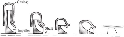 |
||||
| Specific speed Ns | |||||
| U.S. nomenclature | 500–1000 | 1000–2000 | 2000–3000 | 3000–6000 | Above 8000 |
| SI consistent units | 0.2–0.3 | 0.4 | 0.6–0.8 | 1.0–2.0 | Above 2.5 |
| Efficiency % | 50–80 | 60–90 | 70–92 | 76–88 | 75–82 |
The impeller tip speed in centrifugal pumps is limited by design and material strength considerations and ranges between about 200 to 450 m/sec or roughly 655 to 1475 ft/sec. Using titanium (lower in density than steel) and with machined unshrouded impellers tips speeds of over 2150 ft/sec are now possible and have been used on the pump shown in Fig. 10–2. For cast impellers this limiting value is lower than for machined impellers. This maximum impeller tip speed determines the maximum head that can be obtained from a single stage. The impeller vane tip speed u is the product of the shaft speed, expressed in radians per second, and the impeller radius and is related to the pump head ΔH by
where ψ, a velocity correction factor, has values between 0.90 and 1.10 for different designs, though for many pumps, ![]() .
.
The volumetric flow rate Q defines the impeller inlet and outlet areas according to the equation of continuity. Diameters obtained from this equation should be in the proportion indicated by the diagrams for a given specific speed in Table 10–2. The continuity equation for an incompressible liquid is
where the subscripts 1 and 2 may refer to impeller inlet and outlet sections, all areas A being measured normal to their respective flow velocity ![]() . The inlet velocity
. The inlet velocity ![]() ranges usually between 2 and 6 m/sec or 6.5 to 20 ft/sec and the outlet velocity
ranges usually between 2 and 6 m/sec or 6.5 to 20 ft/sec and the outlet velocity ![]() between 3 and 15 m/sec or 10 to 47 ft/sec. For a “somewhat compressible liquid,” such as liquid hydrogen, the density ρ will change with pressure. Here, the continuity equation is given in terms of mass flow rate
between 3 and 15 m/sec or 10 to 47 ft/sec. For a “somewhat compressible liquid,” such as liquid hydrogen, the density ρ will change with pressure. Here, the continuity equation is given in terms of mass flow rate ![]()
The head developed by the pump will then also depend on the change in density. The liquid power output of the pump may be found from the volumetric flow rate Q (m3/sec) multiplied by the pressure rise of the pump (discharge pressure minus suction pressure, in N/m2).
Pump performance is limited by cavitation, a phenomenon that occurs when the static pressure at any point in a fluid flow passage becomes less than the fluid's local vapor pressure. Cavitation is discussed in Refs. 10–1 to 10–5, , and 34. When the local vapor pressure of the liquid exceeds the local absolute pressure, then vapor bubbles will form at that location and such vapor bubbles formation in the low‐pressure regions cause cavitation. These bubbles collapse when they reach regions of higher pressure, that is, when the static pressure in the fluid is above the vapor pressure. In centrifugal pumps cavitation is most likely to occur just behind the leading edge of the pump impeller vane at the impeller inlet because here is where the lowest absolute pressure is encountered. Any excessive formations of vapor cause the pump discharge mass flow to diminish and fluctuate and reduces thrust and makes combustion erratic.
Bubbles that travel along the pump impeller surface from the low‐pressure region (at the leading edge of the vane where they are formed) downstream to the higher‐pressure region collapse. These sudden collapses create local high‐pressure pulses that may cause excessive stresses and erosion at the impeller surface. In most rocket applications, this cavitation erosion is not as serious as in common water or chemical pumps usage because their cumulative duration is relatively short and the erosion of the impeller is not usually extensive. However, it has been a concern with some test facility transfer pumps. It is also believed that excessive bubbles may be a cause for combustion vibrations (see Chapter 9).
The required suction head (Hs)R is the limit value of the head at the pump inlet (above the local vapor pressure); below this value cavitation in the impeller may occur. It is a function of the pump and impeller design and its value increases with flow as can be seen in Fig. 10–7. To avoid cavitation, the suction head above the vapor pressure required by the pump (Hs)R must always be less than the available or net positive suction head furnished by the suction pipe line up to the pump inlet (Hs)A, that is, ![]() . The required suction head above vapor pressure can be determined from the suction‐specific speed S and the volume flow rate Qe at maximum efficiency:
. The required suction head above vapor pressure can be determined from the suction‐specific speed S and the volume flow rate Qe at maximum efficiency:
The suction‐specific speed S depends on the quality of design and the specific speed Ns, as shown in Table 10–2. The suction‐specific speed S has values between 5000 and 60,000 when using ft‐lbf units. For pumps with poor suction characteristics, it has values nearer 5000; for the best pump designs without cavitation, it has values near 10,000 and 25,000, and for pumps with limited and controllable local cavitation, it has values above 40,000. In Eq. 10–14 the required suction head (Hs)R is usually defined as the critical suction head at which the developed pump discharge head has been diminished arbitrarily by 2% in pump tests with increasing throttling in the suction side. Turbopump development has, over the last several decades, led to impeller designs that can operate successfully with considerably more cavitation than this commonly accepted 2% head loss limit. Inducers are now designed to run stably with extensive vapor bubbles near the leading edge of their vanes, but these bubbles collapse at the vane's trailing end. Inducers can now operate at S‐values above 80,000. A discussion of one design method for impeller blades can be found in Ref. 10–8.
The head that is available at the pump suction flange, or net positive suction head or available suction head above vapor pressure, (Hs)A is an absolute head value determined from the tank pressure (the absolute gas pressure in the tank above the liquid level), the elevation of the propellant level above the pump inlet, diminished by the friction losses in the line between tank and pump and by vapor pressure of the fluid. When a flying vehicle is undergoing accelerations, the head due to elevation must be corrected accordingly. These various heads are defined in Fig. 10–8. The term (Hs)A is often abbreviated as NPSH and is the maximum head available for suppressing cavitation at the inlet to the pumps:
If additional head is required by the pump, the propellant may have to be pressurized by external means, such as by the addition of another pump in series (called a booster pump) or by gas pressurization of the propellant tanks. This latter method requires thicker tank walls and, therefore, heavier tanks and a bigger gas‐pressurizing system. For example, the oxygen tank of the German V‐2 was pressurized to 2.3 atm, partly to avoid pump cavitation. For a given value of (Hs)A, propellants with high vapor pressure require correspondingly higher tank pressures and heavier inert tank masses; here, pumps with low required suction pressures usually permit designs with high shaft speeds, small diameters, and low pump inert mass. A small value of (Hs)R is desirable because it may permit a reduction of the requirements for tank pressurization and, therefore, a lower inert tank mass. The value of (Hs)R will be small when the impeller and fluid passages are well designed and when shaft speeds N are low. Very low shaft speeds, however, require large‐diameter pumps, which become excessively heavy. The trend in selecting centrifugal pumps for rocket applications has been to select the highest shaft speed that gives a pump with a low enough value of (Hs)R, that does not require excessive tank pressurization or other design complications, thereby permitting relatively lightweight pump designs. This places a premium on pumps with good suction characteristics.

Figure 10–8 Definition of pump suction head.
There have been some low‐thrust, low‐flow, experimental engines that have used positive displacement pumps, such as diaphragm pumps, piston pumps, or rotary displacement pumps (gear and vane pumps). For low values of specific speed Ns, these pumps have much better efficiencies but their discharge pressure fluctuates with each stroke and they are noisy.
One method to provide a lightweight TP with low vehicle tank pressure is to use an inducer, which is a special pump impeller usually mounted on the same shaft and rotating at the same speed as the main impeller. It has a low head rise and therefore a relatively high specific speed. Inducers are located immediately upstream of the main impeller. They are basically axial‐flow pumps with a spiral impeller, and many will operate under slightly cavitating conditions. Here, the inducer stage's head rise (typically, 2 to 10% of the total pump head) has to be just large enough to suppress cavitation in the main pump impeller; this allows a smaller, lighter, higher‐speed main pump. Figures 10–2 and 10–9 and Reference 10–18 show such inducers. Reference 10–19 describes pump testing with an inducer. Most TPs today have inducers ahead of the pump impellers.

Figure 10–9 Fuel pump inducer impeller of the Space Shuttle main engine low‐pressure fuel turbopump. It had a diameter about 10 in., a nominal hydrogen flow of 148.6 lbm/sec, a suction pressure of 30 psi, a discharge pressure of 280 psi at 15,765 rpm, an efficiency of 77%, and a suction specific speed of 39,000 when tested with water.
Courtesy of Aerojet Rocketdyne.
Several TPs use impellers with double inlets. Not shown in Figs. 10–1, 10–3 and schematically in 10‐4 are pumps, impellers and housings with two inlets (one on each side of the volute). Such design doubles the pump inlet area, reduces the inlet velocity to about half and raises the pump inlet pressure, all of which improves the pump's cavitation resistance.
Influence of Propellants
For the same power and mass flow rate, pump head is inversely proportional to propellant density. Since liquid pumps are basically constant‐volume flow devices, the propellant with the highest density requires less head, less power, and thus allows smaller pump assemblies.
Because many propellants are dangerous to handle, special provisions have to be made to prevent any leakage through the shaft seals. With spontaneously ignitable propellants, leakages can lead to fires in the pump compartment and may also cause explosions. Multiple seals are often used with drainage provisions that safely remove or dispose any propellants that flow past the first seal. Inert‐gas purges of seals have also been used to remove hazardous propellant vapors. The sealing of corrosive propellants puts very severe requirements on sealing materials and design. With cryogenic propellants pump bearings are usually lubricated by the propellant itself since ordinary lubricating oils would freeze at such low pump hardware temperatures.
Centrifugal pumps need to operate at their highest possible pump efficiency. This efficiency increases with volume flow rate and reaches a maximum value of about 90% for very large flows (above 0.05 m3/sec) and specific speeds above about 2500 (see Refs. 10–1 and 10–8). Most propellant pump efficiencies are between 30 and 70%. Pump efficiencies are reduced by surface roughness of casing and impellers, the power consumed by seals, bearings, and stuffing boxes, and by excessive wear‐ring leakage and poor hydraulic designs. The pump efficiency ηP is defined as the fluid power divided by the pump shaft power PP:
A correction factor of 550 ft‐lbf/hp has to be added when PP is given in horsepower, the head H in feet, and the volume flow Q in ft3/sec.
10.6 TURBINES
The turbine must provide adequate shaft power for driving propellant pumps (and sometimes also auxiliaries) at the desired shaft speeds and torques. Turbines derive their energy from a gaseous working fluid expansion through fixed nozzles and rotating turbine blades. Such blades are mounted on disks which are fastened to the shaft. The working gas expands to a high, nearly tangential, velocity through inclined nozzles and then flows through specially shaped blades, where the flow is turned as the gas kinetic energy is converted into tangential forces on each blade. These forces cause the turbine wheel to rotate (see Refs. 10–1 to 10–5, 10–20 and 10–21).
Classification and Description
The majority of turbines have blades at their disk periphery and the gas flow is axial, similar to the axial‐flow pattern shown for pumps in Table 10–2 and the single‐stage turbine of Fig. 10–1. However, there are some turbines with radial flow (particularly those operating at high shaft speeds), as the one shown in Fig. 10–2. Generally, there are two types of axial‐flow turbines of interest to rocket pump drives: impulse turbines and reaction turbines, as shown in Fig. 10–10. In impulse turbines, the enthalpy of the working fluid is converted into kinetic energy within the first set of stationary turbine nozzles and not in the rotating blade elements. High‐velocity gases are delivered (at a small angle to a tangential direction) to the rotating blades, and blade rotation takes place as a result of the impulse imparted by the momentum of the fluid stream of high kinetic energy to the rotating blades that are mounted on the turbine disk. The velocity‐staged impulse turbine has a stationary set of blades that change the flow direction after the gas leaves the first set of rotating blades and directs the gas to enter a second set of rotating blades in which the working fluid gives up further energy to the turbine wheel. In pressure‐staged impulse turbines, the expansion of the gas takes place in all the stationary rows of blades. In reaction turbines the expansion of the gas is roughly evenly split between rotating and stationary blade elements. The high‐pressure drop available for turbine working‐fluid expansion in gas generator cycles favors simple, lightweight one‐ or two‐stage impulse turbines for high thrust engines. Many rocket propulsion turbines are neither pure impulse nor reaction turbines, but often operate fairly close to impulse turbines with a small reaction in the rotating vanes. In some turbines, the rotating blades are mechanically fastened to the rotating turbine disk. Other turbines use a single piece of high‐strength alloy metal where the blades have been machined out—this type is called “blisk.” The RS‐68 rocket engine has such blisks.

Figure 10–10 Top view diagram, pressure and velocity profiles, and efficiency curves for impulse and reaction type turbines. The velocity ratio is the pitch line velocity of the rotating blades u divided by the theoretical gas spouting velocity  derived from the enthalpy drop.
Adapted with permission from Refs. 10–3 and 10–19.
With some gas generator engine cycles the turbine exhaust gases pass through a supersonic nozzle at the exit of the turbine exhaust duct flow (see Fig. 1–14). The relatively high turbine outlet pressure gives critical flow conditions at the nozzle throat (particularly at high altitudes) and thereby assures constant turbine outlet pressure and constant turbine power which will not vary with altitude. Furthermore, this nozzle provides a small additional thrust to the engine (see Chapter 3).
Turbine Performance and Design Considerations
The power supplied by the turbine is given by a combined version of Eqs. 3–1 and 3–7:
The power Pt delivered by the turbine is proportional to the turbine efficiency ηt, the mass flow through the turbine ![]() , and the available enthalpy drop per unit of flow Δh. The units in this equation must be consistent (
, and the available enthalpy drop per unit of flow Δh. The units in this equation must be consistent (![]() ). As seen, this enthalpy decrease is a function of the specific heat cp, the nozzle inlet temperature T1, the pressure ratio across the turbine, and the ratio of the specific heats k of the turbine gases. For gas generator cycles the pressure drop between the turbine inlet and outlet is relatively high, but the turbine flow is small (typically 2 to 5% of full propellant flow). For staged combustion cycles this pressure drop is very much lower, but the turbine flow is much larger.
). As seen, this enthalpy decrease is a function of the specific heat cp, the nozzle inlet temperature T1, the pressure ratio across the turbine, and the ratio of the specific heats k of the turbine gases. For gas generator cycles the pressure drop between the turbine inlet and outlet is relatively high, but the turbine flow is small (typically 2 to 5% of full propellant flow). For staged combustion cycles this pressure drop is very much lower, but the turbine flow is much larger.
In very large liquid propellant engines with high chamber pressure, turbine power can reach over 250,000 hp, and for small engines it can perhaps be around 35 kW or 50 hp.
According to Eq. 10–3, the power delivered by the turbine Pt equals the sum of the power required by the propellant pumps, the auxiliaries mounted on the TP (such as hydraulic pumps, electric generators, tachometers, etc.), and power losses in hydraulic friction, bearings, gears, seals, and wear rings. Usually, these losses are small enough to be neglected. Effects of turbine gas flows on the specific impulse of rocket engines are discussed in Section 6.6. For gas generator engine cycles, the rocket engine designer is interested in obtaining high turbine efficiencies and high turbine inlet temperatures T1 in order to reduce the flow of turbine working fluids, and for gas generator cycles also in raising the overall effective specific impulse and, therefore, reducing the propellant mass required for driving the turbine. Computer analyses of gas flow behavior and turbine blade geometry have yielded efficient blade designs.
Presently, better turbine blade materials (such as unidirectionally solidified single crystals) and specialty alloys allow turbine inlet temperatures up to 1400 K (or about 2050 °F) and perhaps to 1600 K (or 2420 °F); at these higher temperatures or higher gas enthalpies the required turbine flow is reduced. When using special steel alloys for blade and disk materials, reliability, gas temperature variations (nonuniformities), and cost considerations have reduced actual turbine inlet temperatures to more conservative values, such as 1150 to 1250 °F or about 900 to 950 K. Turbine stage efficiencies for certain types of rocket TPs are shown in Fig. 10–10. Maximum blade speeds with good design and strong high‐temperature materials are typically 400 to 700 m/sec or about 1300 to 2300 ft/sec; higher blade speeds generally get improved efficiencies. For the efficiency to be high turbine blade and nozzle profiles need to have smooth surfaces. Small clearances at the turbine blade tips are also needed to minimize leakage around the blades.
Different organizations define turbine efficiency differently. One way to define turbine efficiency ηt is to divide the turbine power output LN (torque L and shaft speed N) by the ideal isentropic enthalpy drop (note that actual pressure drops and actual Δhs are usually higher than ideal):
Here, Δh is the isentropic gas expansion enthalpy drop across the turbine nozzles and the turbine buckets or blades (moving and stationary) per unit gas mass flow ![]() . It is typically based on a uniform gas with uniform properties flowing across a section, the perfect gas equation of state, no leakage or alternatively only nominal leakage around the blades, and precise blade contours. Even small clearances at the tip of turbine blades may cause substantial losses, particularly at small turbine diameters and small blade heights. Some organizations also include a few unavoidable losses in defining the ideal power.
. It is typically based on a uniform gas with uniform properties flowing across a section, the perfect gas equation of state, no leakage or alternatively only nominal leakage around the blades, and precise blade contours. Even small clearances at the tip of turbine blades may cause substantial losses, particularly at small turbine diameters and small blade heights. Some organizations also include a few unavoidable losses in defining the ideal power.
A proper turbine efficiency may be realized only when the TP design has efficient turbine blade contours and allows high blade speeds. Power input to the turbine can be regulated by controlling the gas flow and gas temperatures to the turbine inlet through valves or orifices.
10.7 APPROACH TO TURBOPUMP PRELIMINARY DESIGN
This section presents one approach to TP analysis and selection of key TP features, and gives estimates of some key parameters for preliminary design. Principal criteria (high performance or efficiency, minimum mass, high reliability, and low cost) need to be evaluated and prioritized for each vehicle mission including all major rocket engine components. For example, high efficiency and low mass usually lead to low design margins, and thus lower reliability. A higher shaft speed will allow lower mass TPs, but ones that cavitate more readily and require higher tank pressures and thus heavier vehicle tanks (these usually outweigh any mass savings in the TP).
Engine requirements provide the basic goals for TP preliminary designs, namely, propellant flows, pump outlet or discharge pressures (which must equal the chamber pressure plus pressure drops in the piping, valves, cooling jacket, and injector), the best engine cycle (shown in Fig. 6–8), as well as any start delays and needs for restart or throttling. Also, propellant properties (density, vapor pressure, viscosity, or boiling point) must be known. Some design criteria are explained in Refs. 10–2 and 10–3, and basic texts on turbines and pumps are listed as Refs. 10–4 to 10–8.
Usually, pump preliminary analyses are done first. Avoiding excessive cavitation in the pump sets a key pump parameter, namely the maximum pump shaft speed. This is the highest possible shaft speed, which in turn allows the lightest TP mass. When excessive cavitation occurs at the leading edge of the main impeller, then the flow becomes unsteady, leading to lower thrust and possible combustion instabilities. The amount of total pressure in the vehicle (gas pressure in propellant tanks plus the static elevation pressure) that can be made available to the rocket engine (at the pump inlet) for suppressing cavitation has to be larger than the impeller vanes' own pressure limit to cavitate. This allows determination of shaft speed, which in turn establishes approximate pump efficiencies, impeller tip speeds (usually also limited by the material strength of the impeller), number of pump stages, and/or key dimensions of the impeller.
There are several design variations or geometrical arrangements for transmitting turbine power to one or more propellant pumps and an initial selection has to be made; some are shown schematically in Fig. 10–4. If there is a mismatch between optimum pump speed and optimum turbine speed (which is usually higher), it may save inert mass and turbine drive gas mass to interpose a gear reduction between their shafts. See Fig. 6–10 and Figs. 10–4d and 10–4f. For the past three decades designers have preferred to use a direct drive, which avoids the complication of a gear case but at a penalty both in efficiency and in the amount of turbine drive propellant gas required. See Figs. 6–11, 10–1, 10–2 and 10–4e.
Key turbine parameters are estimated by equating the power output of the turbine to the power demand of the pumps. If the pump is driven directly, that is, without a gear case, then pump speed and turbine speed must be equal. From the properties of the turbine drive gas (temperature, specific heat, etc.), the strength limits of turbine materials, and likely pressure drops, it is possible to determine the basic blade dimensions (pitch line velocity, turbine nozzle outlet velocity, number of rows [stages] of blades, turbine type, or turbine efficiency). Any particular arrangement or geometry of major TP components results from their selection process. Most propellant pumps have a single‐stage main impeller but for liquid hydrogen, because of the very low density, a two‐ or three‐stage pump is normally needed. Usually, some design limit is reached which requires one or more iterations. The arrangement of the major TP components (Fig. 10–4) is also influenced by the position of the bearings on the shaft. For example, the placement of a bearing in front of an impeller inlet is not desired because this will cause turbulence, distort the flow distribution, raise the suction pressure requirement, and make cavitation more likely to occur. Also, bearings positioned close to a turbine will experience high temperatures, and these influence lubrication needs from the propellant and may demand more cooling of the bearings.
The use of booster pumps allows lower tank pressures and thus a lower inert vehicle mass while providing adequate suction pressures to the main pump inlet. See Ref. 10–12. Booster pumps have been used in the Space Shuttle main engine and the Russian RD‐170, as seen in Figs. 6–11 and 11–2. Some booster pumps have been driven by a booster turbine using small flows of a high‐pressure liquid propellant tapped off the discharge side of the main pump. The discharged turbine liquid then gets mixed with the main propellant flow at the discharge of the booster pump.
Mass is at a premium in all flying vehicles and feed systems are selected to have a minimum combined mass of turbines, pumps, gas generator, valves, tanks, and gas generator propellants. Design considerations of TPs include thermal stresses, warpage due to thermal expansion or contraction, axial loads, adequate clearances to prevent internal rubbing yet minimizing leakage, alignment of bearings, provisions for dynamic balancing of rotating subassemblies, mountings on elastic vehicle frames without inducing external forces, and avoiding undue pressure loads in pipes flowing liquids or gases.
The critical speed of any rotating assembly equals its natural vibration frequency when not rotating but supported on knife edges at the same two locations as the center of its bearings. At the critical speed and under load, shaft deflections will amplify and any small shaft‐slope changes (e.g., 0.001 to 0.003 in.) at any bearing may cause bearing failure. Some types of shaft seals will also likely fail. The rotating assembly of a TP consists of the shaft, turbine drive and blades, pump impeller, and parts of bearings and seals. A TP's operating shaft speed must never reach any critical value at which it would fail. Therefore, TP operating speeds are usually well below the critical speed. There are some exceptions when the operating speed can exceed critical and these occur during start and stop transients.
Designers can tailor the critical speed by using large‐diameter stiff shafts, rigid bearings with stiff bearing support housings, short distances between the two bearings, and little or no shaft overhangs beyond the bearings—all these will increase critical shaft speeds. A higher critical speed will allow higher pump operation speeds and result in smaller, lighter TPs. Also, the natural resonant frequency of key components (such as piping subassemblies, injector domes, or thrust structures) must not coincide with the critical shaft speed because this can lead to higher stresses and flow disturbances in these components. Critical speeds and resonance frequencies of key components can usually be determined analytically and designs may be altered through changes in mass and stiffness (spring forces).
Solving methods for various internal vibration problems, such as whirl in bearings and blade vibrations, are reported in Ref. 10–16, and the dynamics of propellant flow in pumps can be found in Ref. 10–15. Whenever a pump blade tip of passes the stationary tongue of a pump volute, a pressure wave is generated in the liquid; the frequency of this wave is the product of the number of pump vanes and the speed of the vane tip. Vibrations external to TPs, such as those generated by the thrust chamber (see Chapter 9) should not influence TP operation.
The bearings in most existing TPs are high precision, special metal alloy ball bearings (Ref. 10–18). A few are roller bearing types which have a higher radial load capacity. Some ball bearings can take both radial and axial loads. Early ball and roller bearings were limited in the loads and speeds at which they could operate reliably. In some TP designs, limits on bearing loads and speeds (and thus minimum TP sizes) were determined by shaft speeds rather than by cavitation limits of the pumps. Various types of bearings and many types of seals have been explored and tested in laboratory fixtures or in experimental TPs. They include hydrostatic (precision sleeve type) bearings, foil bearings, and magnetic bearings (Ref. 10–13). As far as the authors know, none of these have as yet found their way into a production TP. The variety of available static and dynamic seals is relatively large and seal selection is strongly influenced by the preferences of the design organization (Ref. 10–14).
When the TP is part of a reusable rocket engine, it becomes a more complex system. For example, such system may include provisions to allow for inspection and automatic condition evaluation after each mission or flight. This may encompass access holes for boroscope instruments for bearing inspections, checking for cracks in highly stressed parts (turbine blade roots or hot‐gas, high‐pressure manifolds), and measurement of shaft torques (to detect possible binding or warpage).
The number of different materials for TP construction has increased. For example, for high‐speed, high‐load, ball bearings a new ball material (silicon nitride) has been successfully introduced. Relatively common materials, such as stainless steels, have in part been replaced by superalloys, such as Inconel. Powder metallurgy has found its way into pump impellers and turbine parts, see Ref. 10–22; although their strength is not really better than forged or cast materials, they have smoother surfaces (lower friction), uniform physical properties, and can be fabricated into more complex shapes (Ref. 10–22).
There are no allowable warm‐up times available for rocket turbines. The sudden admission of hot gases at full flow causes severe thermal shock and thermal distortion, increasing chances for rubbing between moving and non‐moving metal parts. The most severe stresses in turbine blades are often thermal stresses; they arise during engine start‐ups when the blade leading edge becomes very hot while its other parts are still cold.
For low‐thrust engines shaft speeds can be very high, such as over 100,000 rpm. Also, turbine blade height can be very short and friction as well as other losses may become prohibitive. In order to obtain reasonable blade heights, partial admission turbine designs have been used; here a portion of the turbine nozzles are effectively plugged or eliminated.
10.8 GAS GENERATORS AND PREBURNERS
The purpose of gas generators or preburners is to supply the “warm” gases (usually between 600 and 2000 °F or 315 to 1200 °C) that drive the turbine of a TP. Gas generators are used exclusively with liquid propellant rocket engines that operate on a gas generator engine cycle, and preburners are used exclusively with rocket engines that operate on a staged combustion cycle and usually at higher combustion pressures. Table 10–3 details some differences between these two and Table 6–6 and Fig. 6–8 show the engine cycles. See Refs. 10–1 to 10–5. The gas temperatures mentioned above allow for an uncooled turbine with uncooled inlet and outlet ducts, and uncooled blades and turbine nozzles.
Table 10–3 Comparison of Key Characteristics of Gas Generators and Preburners
| Parameter | Gas Generator | Preburner |
| Engine cycle | Gas generator cycle | Staged combustion cycle |
| Chamber pressure | Usually equal or lower than thrust chamber pressure | 30–90% higher than its thrust chamber pressure |
| Mass flow as % of total propellant flow | 1–7 | 45–90 |
| Cooling | Usually uncooled | Usually uncooled, but may be partially cooled |
| Inert mass | Relatively light | Heavy |
| Size | Relatively small | Can be large |
| Flow of warm turbine exhaust gas | Out of vehicle into ambient atmosphere | Into injector of main thrust chamber |
Gas generators and combustion devices each comprise a combustion chamber, an injector, and pipes or ducts leading to the turbine. See Ref. 10–6. They all have separate dedicated propellant control valves. Warm gases flow subsonically from the gas generator or preburner through pipes or manifolds into multiple nozzles in the turbine and then flow supersonically through row(s) of turbine blades that extract the driving energy for the propellant pumps. Requirements for gas generators or preburners include the delivery of warm gases at the intended mass flows, pressures, and design temperatures together with essentially uniform gas temperatures across the flow path to the turbine and without high gas temperature spikes. Combustion instability problems are extremely rare.
The typical gas generator has relatively small flows, typically 2 to 3% of the total engine propellant flow. It makes little difference in pump power or TP design if the gas in the gas generator is oxidizer rich or fuel rich. The authors have found that a majority of gas generators run fuel rich.
For staged combustion rocket engines with oxidizer‐rich gas preburners, oxidizer flows with a small portion fuel flows supply the preburner. The gas pressure in the preburner is substantially higher than the thrust engine's chamber pressure. Preburner gases flow through the turbine that drives the propellant pumps, and then the turbine exhaust flows to the thrust chamber injector. For an oxidizer‐rich preburner with a liquid oxygen/RP‐1 propellant combination a typical mixture ratio would be 54 parts liquid oxygen to one part fuel. Oxidizer pump powers need to be substantially higher than those for engines without a preburner resulting in longer and heavier (but perhaps more efficient) pumps. The much smaller fuel flows to the preburner can utilize a separate “kick” pump or an extra low flow stage on the fuel pump. The majority of operational engines with a staged combustion cycle operate with an oxidizer‐rich preburner gas.
For fuel rich preburners, all the fuel goes to the preburner and only a small oxidizer flow is needed. The preburner operates at higher propellant pressures compared to engines without preburners and this also results in heavier thrust chambers. For a liquid oxygen/RP‐1rocket engine, the mixture ratio in the preburner would typically be about three parts of fuel to one part of oxidizer (or 0.33).
In ground‐based test facilities, any unexpected leak or spill of hot fuel‐rich gases will most likely ignite with ambient air resulting in a fire whereas a hot oxidizer‐rich leak will not. However, the latter gases are very corrosive and can react with all surfaces they come in contact with (oxidizing metallic surfaces and oxidizing and/or causing fires with organic materials such as rubber gaskets).
Gas generators are shown as a component of the engine in Fig. 1–4 and Ref. 10–4, and preburners are shown in Figs. 6–1, 6–11, and 11–2. Propellants supplied to the gas generator or the preburner are usually tapped off from discharges of the engine main pumps. When starting an engine, the turbomachinery needs to be brought up to rated speed before propellants can be supplied to the thrust chambers at their full operating pressure. Such required gas generator starting has also been done with a solid propellant starting cartridge (running only a few seconds), or an auxiliary set of small propellant tanks pressurized by a cold gas (also running only for short duration), or by letting the engine “bootstrap” itself into starting using the tank pressure augmented by the existing liquid column head in the vehicle tanks and feed system pipe lines—usually called “tank head” start (which requires more time to start). A discussion of engine starts and tank pressurization can be found in Section 6.5 and of thrust chamber starts in Section 8.6.
In the past, monopropellant gas generators were common using either 80 or 90% hydrogen peroxide or pure hydrazine to provide the warm gases, usually through catalytic decomposition in a bed of solid catalysts. Here, a simpler gas generator system is required (only one tank and one set of valves, instead of two), having no mixture ratio adjustments, and with predictable, fully reproducible uniform warm gas temperatures without potential temperature spikes. The key disadvantages were the complications for providing a third propellant, potential propellant hazards, lower performances, and/or the higher mass of propellant for making the warm gases necessary for providing the required power.
SYMBOLS
| a | gear ratio |
| A | area, m2 (ft2) |
| cp | specific heat at constant pressure, J/kg K (Btu/lb°R) |
| co | ideal nozzle exit gas velocity |
| D | diameter, m (ft) |
| g0 | sea‐level acceleration of gravity, 9.806 m/sec2 (32.17 ft/sec2) |
| H | head, m (ft) |
| (Hs)A | available pump suction head above vapor pressure, often called net positive suction head, m (ft) |
| (Hs)R | required pump suction head above vapor pressure, m (ft) |
| k | ratio of specific heats |
| L | torque, Nm (ft‐lbf) |
| mass flow rate, kg/sec (lbm/sec) | |
| N | shaft speed, rpm (rad/sec) |
| Ns | specific speed of pump |
| p | pressure, N/m2 (lbf/in.2) |
| P | power, W (hp) |
| Pb | power of auxiliaries, bearings, rubbing seals, friction |
| Q | volumetric flow rate, m3/sec (ft3/sec) |
| S | suction specific speed of pump |
| T | absolute temperature, K (°R) |
| u | impeller tip speed or mean blade speed, m/sec (ft/sec) |
| liquid flow velocity, m/sec (ft/sec) |
Greek Letters
| η | Efficiency |
| ρ | density, kg/m3 (lb/ft3) |
| ψ | velocity correction factor |
Subscripts
| e | maximum efficiency condition |
| f | Fuel |
| o | Oxidizer |
| p | Pump |
| t | Turbine |
| 0 | initial condition |
| 1 | pump or turbine inlet, or chamber condition |
| 2 | pump or turbine outlet, or chamber condition |
PROBLEMS
- A rocket propulsion system with two TPs delivers the fuel, namely unsymmetrical dimethylhydrazine (UDMH), at a pump discharge pressure of 555 psia, a suction pressure of 25 psi, a flow of 10.2 lbm/sec, at 3860 rpm, and a fuel temperature of 68 °F. Using UDMH properties from Table 7–1 and Fig. 7–1 and its efficiency from Table 10–2, determine the following:
- The fuel pump power for these nominal conditions.
- If the fuel flow is reduced to 70% of nominal, what will be the approximate power level, discharge pressure, and shaft speed? Assume that the oxidizer pump is also reduced by 70% and also the gas flow to the turbines, but that the gas temperature is unchanged.
- If the anticipated temperature variation of the propellants is between − 40°F and + 120°F, describe qualitatively how this variation will affect the power level, shaft speed, and the discharge pressure of the fuel pump.
- What are the specific speeds of the four SSME pumps? (Use the data given in Table 10–1.)
- Compute the turbine power output for a gas consisting of 64% by weight of H2O and 36 % by weight of O2, if the turbine inlet is at 30 atm and 658 K with the outlet at 1.4 atm and with 1.23 kg flowing each second. The turbine efficiency is 37%.
- Compare the pump discharge gauge pressures and the required pump powers for five different pumps using water, gasoline, alcohol, liquid oxygen, and diluted nitric acid. The respective specific gravities are 1.00, 0.720, 0.810, 1.14, and 1.37. Each pump delivers 100 gal/min, a head of 1000 ft, and has arbitrarily a pump efficiency of 84%.Answers: 433, 312, 350, 494, and 594 psi; 30.0, 21.6, 24.3, 34.2, and 41.1 hp.
- The following data are given for a liquid propellant rocket engine:
Determine the engine system mixture ratio and the system specific impulse.Answer: 3.07 and 208 sec.Thrust 40,200 lbf Thrust chamber specific impulse 210.2 sec Fuel Gasoline (specific gravity 0.74) Oxidizer Red fuming nitric acid (sp. gr. 1.57) Thrust chamber mixture ratio 3.25 Turbine efficiency 58% Required pump power 580 hp Power to auxiliaries mounted on turbopump gear case 50 hp Gas generator mixture ratio 0.39 Turbine exhaust pressure 37 psia Turbine exhaust nozzle area ratio 1.4 Enthalpy available for conversion in turbine per unit of gas 180 Btu/lbm Specific heat ratio of turbine exhaust gas 1.3
REFERENCES
- 10–1. G. P. Sutton, “Turbopumps, a Historical Perspective,” AIAA Paper 2006‐7531, Jul. 2006.
- 10–2. D. K. Huzel and D. H. Huang, “Design of Turbopump Feed Systems,” Chapter 6 in Design of Liquid Propellant Rocket Engines, rev. ed., Vol. 147, Progress in Astronautics and Aeronautics, AIAA, Reston, VA, 1992.
- 10–3. M. L. Strangeland, “Turbopumps for Liquid Rocket Engines,” Threshold, an Engineering Journal for Power Technology, No. 3, Rocketdyne Propulsion and Power, Summer 1988, pp. 34–42.
- 10–4. G. P. Sutton, “Turbopumps,” Chapter 4.4, and “Gas Generators, Preburners and Tank Pressurization,” Chapter 4.5, in History of Liquid Propellant Rocket Engines, AIAA, Reston, VA, 2006.
- 10–5. “Turbopump Systems for Liquid Rocket Engines,” NASA Space Vehicle Design Monograph, NASA SP‐8107, Aug. 1974.
- 10–6. Personal communications with personnel from Pratt & Whitney Rocketdyne, Northrop Grumman, and The Aerospace Corporation, 2006 to 2008.
- 10–7. A. Minick and S. Peery, “Design and Development of an Advanced Liquid Hydrogen Turbopump,” AIAA Paper 98‐3681, Jul. 1998, and G. Crease, R. Lyda, J. Park, and A. Minick, “Design and Test Results of an Advanced Liquid Hydrogen Pump,” AIAA Paper 99–2190, 1999.
- 10–8. I. J. Karassik, W. C. Krutzsch, W. H. Frazer, and J. P. Messina (Eds.), Pump Handbook, McGraw‐Hill, New York, 1976 (water hammer and pumps); I. J. Karassik, Chapter 14‐2 in Marks' Standard Handbook for Mechanical Engineers, 10th Ed., McGraw‐Hill, New York, 1978.
- 10–9. C. E. Brennan, Hydrodynamics of Pumps, Concepts ETI, Inc. and Oxford University Press, Oxford, England, 1994.
- 10–10. “Liquid Rocket Engines Turbopump Shafts and Couplings,” NASA Space Vehicle Design Monograph, NASA SP‐8101, Sept. 1972.
- 10–11. “Liquid Rocket Engines Turbopumps Gears,” NASA Space Vehicle Design Monograph, NASA SP‐8100, Mar. 1974.
- 10–12. Y. V. Demyanenko, A. I. Dimitrenko, and I. I. Kalatin, “Experience of Developing Propulsion Rocket Engine Feed Systems Using Boost Turbopump Units,” AIAA Paper 2003‐5072, 2003.
- 10–13. “Liquid Rocket Engine Turbopump Bearings,” NASA Space Vehicle Design Monograph, NASA SP‐8048, Mar. 1971.
- 10–14. Liquid Rocket Engine Turbopump Rotating Shaft Seals. NASA SP‐8121, Feb. 1978.
- 10–15. J. Kurokawa, K. Kamijo, and T. Shimura, “Axial Thrust Analysis on LOX‐Pump,” AIAA Paper 91‐2410, June 1991.
- 10–16. M. C. Ek, “Solving Synchronous Whirl in High Pressure Turbine Machinery of the Space Shuttle Main Engine,” Journal of Spacecraft and Rockets, Vol. 17, No. 3, May–Jun. 1980, pp. 208–218.
- 10–17. R. S. Ruggeri and R. D. Moore, “Method for Prediction of Pump Cavitation Performance for Various Liquids, Liquid Temperatures, and Rotating Speeds,” NASA TN D5292, Jun. 1969.
- 10–18. “Liquid Rocket Engine Turbopump Inducers,” NASA Space Vehicle Design Monograph, NASA SP‐8052, May 1971.
- 10–19. T. Shimura and K. Kamijo, “Dynamic Response of the LE‐5 Rocket Engine Oxygen Pump,” Journal of Spacecraft and Rockets, Vol. 22, No. 2, Mar.–Apr., 1985.
- 10–20. “Liquid Rocket Engine Turbines,” NASA Space Vehicle Design Criteria Monograph, NASA SP‐8110, Jan. 1974.
- 10–21. S. Andersson and S. Trollheden, “Aerodynamic Design and Development of a Two‐Stage Supersonic Turbine for Rocket Engines,” AIAA Paper 99–2192, 1999.
- 10–22. D. Guichard and A. DuTetre, “Powder Metallurgy Applied to Impellers of Vinci Turbopump,” International Symposium for Space Transportation of the XXI Century, in CD ROM of the symposium, May 2003.