
CHAPTER 14
SOLID PROPELLANT COMBUSTION AND ITS STABILITY
In this the third of four chapters on solid propellant rocket motors we discuss combustion of solid propellants, physical and chemical processes of burning, ignition or start‐up process, extinction of burning, and combustion instability.
When compared to other power plants, the combustion process in rocket propulsion systems is very efficient because gas composition in solid propellant reactions is essentially uniform and combustion temperatures are relatively very high; these two accelerate the rate of chemical reaction, helping to achieve nearly complete combustion. As mentioned in Chapter 2, the energy released in combustion can be between 94 and 99.5% of the total available. This is difficult to improve, so rocket motor designers have been concerned not so much with the burning process as with controlling combustion (start, stop, and heating effects) and with preventing the occurrence of combustion instabilities.
14.1 PHYSICAL AND CHEMICAL PROCESSES
Combustion in solid propellant motors involves exceedingly complex reactions taking place in the solid, liquid, and gas phases of heterogeneous mixtures. Not only are the physical and chemical processes occurring during solid propellant combustion not fully understood, but analytical combustion models have remained oversimplified and unreliable. Experimental observations of burning propellants show complicated three‐dimensional microstructures and other flame structures, intermediate products in the liquid and gaseous phases, spatially and temporally variant processes, aluminum agglomerations, nonlinear response behavior, formations of carbon particles, and other complexities yet to be adequately reflected in most mathematical models.
Some insight into the solid propellant combustion process can be gained by understanding the behavior of one major oxidizer ingredient, such as ammonium perchlorate, which has been fairly well studied. This oxidizer is capable of self‐deflagration with a low‐pressure combustion limit at approximately 2 MPa. It has at least four distinct “froth” zones of combustion between 2 and 70 MPa, with the existence of a liquid froth on the surface of the crystal during deflagration between 2 and 6 MPa, and with a change in the energy transfer mechanism (particularly at about 14 MPa). Its influence on combustion is critically dependent on oxidizer purity. Surface regression rates for ammonium perchlorate range from 3 mm/sec at 299 K and 2 MPa to 10 mm/sec at 423 K and 1.4 MPa.
Many of the various polymeric binders used in composite propellants are less well characterized, and their combustion properties may vary, depending on the binder type, heating rate, and combustion chamber pressure.
The addition of powdered aluminum (sized from 2 to 400 µm) is known to favorably influence specific impulse and combustion stability. Photographs of burning aluminum particles show that they usually collect into relatively large agglomerates (100 or more particles) during combustion. The combustion behavior of powdered aluminum depends on several variables, including particle size and shape, surface oxides, binders, and the combustion wave environment. In Ref. 14–1, such solid propellant combustion aspects are extensively described.
Visual observations and simple experimental flame measurements, from strand burner tests, give some insight into the combustion process. For double‐base propellants the combustion flame structure appears to be homogeneous and one‐dimensional along the burning direction, as shown in Fig. 14–1. As heat from the combustion melts, decomposes and vaporizes the solid propellant at its burning surface, the resulting gases emerge already premixed. A brilliantly radiating bright flame zone can be seen where most of the chemical reaction is expected to occur together with a dark zone between the bright flame and the burning surface. Thus, the bright hot reaction zone appears detached from the propellant surface. Combustion does occur inside the dark zone but it is emitting in the infrared. The dark zone thickness decreases with increasing chamber pressure, and any higher heat transfer to the burning surface causes the burning rate to increase. Experiments on strand burners in an inert nitrogen atmosphere, reported in Ref. 14–1 (Kubota, Chapter 2), show this rather dramatically: for pressures of 10, 20, and 30 atm the dark zone thickness is 12, 3.3, and 1.4 mm, respectively, and the corresponding burning rates are 2.2, 3.1, and 4.0 mm/sec. The overall length of the visible flame shortens as the chamber pressure increases and the heat release per unit volume near the surface also increases. In DB propellants, directly over the burning surface in a bright but thin fizz or combustion zone some burning and heat release occurs. Beneath that is a zone of liquefied/bubbling propellant that is thought to be very thin (less than 1 µm) and that has been labeled the foam or degradation zone. Here, the temperature becomes high enough for the solid to vaporize and break up or to degrade into smaller molecules, such as nitrogen dioxide (NO2), aldehydes, or nitric oxide (NO), which exit from the foaming surface. The solid propellant layer underneath the burning surface is being heated by conduction from above.

Figure 14–1 Schematic diagram of the combustion flame structure of a double‐base propellant as seen with a strand burner in an inert atmosphere.
Adapted from Ref. 14–1 with permission of the AIAA.
The presence of burn rate catalysts in the propellant appears to affect the primary combustion zone rather than processes in the condensed phase. These catalyze the reaction at or near the surface, increase or decrease the heat input into the burning surface, and thereby change the amount of propellant that is burning.
A typical flame from an AP/Al/HTPB1 propellant looks very different than that from double‐base propellants, as seen in Fig. 14–2. Here, the luminous flame appears attached to the burning surface, even at low pressures. There is no dark zone. Oxidizer‐rich decomposed gases from the AP particles diffuse into the fuel‐rich decomposed gases from the fuel ingredients, and vice versa. Some solid particles (aluminum, AP crystals, small pieces of binder, or combinations of these) break loose from the surface and they continue to react and degrade while in the gas flow. Thus, the burning gases may contain liquid particles of hot aluminum oxides, which radiate intensively. Both the propellant material and the burning surface are far from homogeneous. The flame structure is unsteady (flickers), three dimensional, and not truly axisymmetric. Flame structures and burning rates from composite‐modified cast double‐base (CMDB) propellants with AP and Al seem to approach those of composite propellants, particularly when their AP content is high. Again there is no dark zone here and the flame structure is unsteady and not axi‐symmetric, exhibiting the more complicated three‐dimensional flame structures.

Figure 14–2 Diagram of the flickering, irregular combustion flame of a composite propellant (69% AP, 19% Al, plus binder and additives) in a strand burner with a neutral atmosphere.
Adapted from Ref. 14–1 with permission of AIAA.
According to Ref. 14–1, the flame structure for double‐base propellants with added nitramine shows only a thin dark zone with a slightly luminous degradation zone at the burning surface. The dark zone also decreases with increased pressure. Any gases issuing from RDX or HMX are essentially neutral (not oxidizing) when decomposing as pure ingredients. For a CMDB/RDX propellant, the degradation products of RDX solid crystals interdiffuse with the gases from the DB matrix just above the burning surface, before the RDX particles can produce monopropellant flamelets. Thus, an essentially homogeneous premixed gas flame is being formed, even though the solid propellant itself is heterogeneous. The flame structure appears to be one‐dimensional. The burning rate of this propellant decreases when the RDX percentage is increased but seems almost unaffected by changes in RDX particle size. Much work has been done to characterize the burning behavior of different solid propellants. See Ref. 14–1 (Chapters 2, 3, and 4 by Kishore and Gayathri, Boggs, and Fifer, respectively) and Refs. 14–2 to 14–8.
The burning rate of all propellants is influenced by chamber pressure (see Section 12–1 and Eq. 12–5), by the initial ambient solid propellant temperature, by any burn rate catalyst present in the propellant, by particle size and the size distribution of solid additives like aluminum, and to a lesser extent by other ingredients and manufacturing process variables. Erosive burning has been discussed in Chapter 12. Combustion instability treated later in this chapter.
14.2 IGNITION PROCESS
In this section we discuss the necessary mechanisms for initiating solid propellant grain combustion. Individual propellants successfully used for igniters are mentioned in Section 13.5. Hardware, types, design, and integration of igniters into the motor are described in Section 15.3. Reference 14–1 contains reviews the state of the art on ignition, data from experiments, and on analytical models.
Solid propellant ignition comprises a series of complicated rapid events that start upon the receipt of a signal (usually electric) that ignites the propellant and this hot gas flows from the igniter to the motor grain surface, spreading of a flame over the entire burning surface area, filling the chamber cavity with gases, and elevating the chamber pressure without serious abnormalities (such as overpressures, combustion oscillations, damaging shock waves, hangfires [delayed ignition], flame extinguishment, and chuffing). The igniter in a solid rocket motor is the component that heats and generates the gases necessary for motor ignition.
Rocket motor ignition must usually be completed in fractions of a second for all but the very large motors (see Ref. 14–9). The pressure inside the motor rises to its equilibrium state in a very short time, as shown in Fig. 14–3. Conventionally, the ignition process is divided into three phases for analytical purposes:
- Phase I, Ignition time lag: The period from the instant the igniter receives its signal until a portion of the grain surface burns and produces hot gases.
- Phase II, Flame‐spreading interval: The time from first ignition of the grain surface until the complete grain burning area has been ignited.
- Phase III, Chamber‐filling interval: The time for completing the chamber gas‐filling process and for reaching equilibrium chamber pressure and mass flow.

Figure 14–3 Typical ignition pressures as a function of time. Shown are the time traces of the igniter propellant and of its motor‐chamber propellant. An electric signal is received a few milliseconds before time zero.
Ignition will be successful once sufficient grain surface is ignited and burning, so that the rocket motor will continue to raise its own pressure up to the operating chamber pressure. If the igniter is not powerful enough, some grain surfaces may burn only for a short time and the flame will be extinguished; the relevant critical processes seem to be located in a gas‐phase reaction above the burning surface, where propellant vapors and/or decomposition products interact with each other and with the igniter gas products.
Satisfactory attainment of equilibrium chamber pressures with full gas flows depends on (1) the characteristics of the igniter and its gas temperature, composition and issuing flow, (2) the motor propellant composition and grain surface ignitability, (3) the radiation and convection heat transfer rates between the igniter gas and grain surface, (4) the grain flame spreading rate, and (5) the dynamics of filling the motor free volume with hot gas (see Ref. 14–10). The quantity and type of caloric energy needed to ignite a particular motor grain in its prevailing environment has a direct bearing on most of the igniters' design parameters—particularly those affecting its required heat output. The ignitability of propellants at any given pressure and temperature is normally shown as a plot of ignition time versus heat flux received by the propellant surface, as in Fig. 14–4; these data were obtained from laboratory open‐air tests. Propellant ignitability is affected by several factors, including (1) propellant formulation, (2) propellant grain surface initial temperature, (3) surrounding pressure, (4) modes of heat transfer, (5) grain surface roughness, (6) propellant age, (7) composition and hot‐solid‐particle content of igniter gases, (8) igniter propellant and its initial temperature, (9) velocity of hot igniter gases relative to the grain surface, and (10) cavity volume and configuration. Figure 14–4 and other data in Chapter 15 both show that the ignition time becomes shorter with increases in both heat flux and chamber pressure. If a shorter ignition delay is required, then a more powerful igniter will be needed. Radiation rates significantly affect ignition transients as described in Ref. 14–11. In Section 15.3 we treat the analysis and design of igniters.
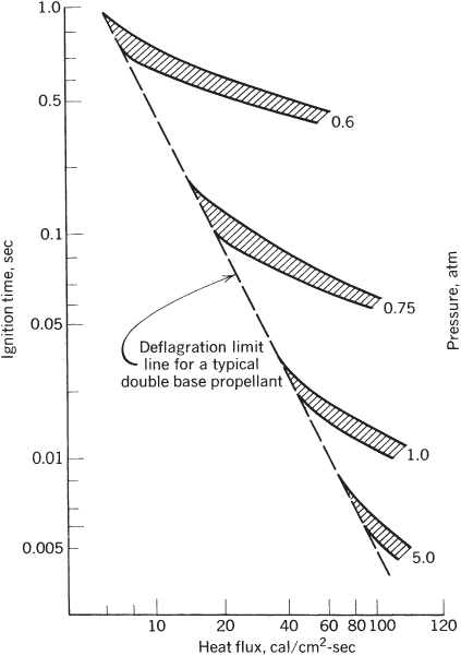
Figure 14–4 Propellant ignitability curves: effect of heat flux on ignition time for a specific rocket motor.
14.3 EXTINCTION OR THRUST TERMINATION
Sometimes it is necessary to stop or extinguish burning in a solid propellant motor before all the propellant has been consumed. For example:
- When a flight vehicle has reached the desired flight velocity (a ballistic missile attaining its predetermined velocity or a satellite achieving its desired orbit height), or when a precise total impulse cutoff is needed.
- As a safety measure, when it appears that a flight test vehicle will unexpectedly fly out of the safe boundaries of a flight test range facility.
- To avoid collisions of stages during stage separation maneuvers (requiring a thrust reversal) for multistage flight vehicles.
- During research and development, when the test requires examining a partially burned rocket motor.
Common mechanisms for achieving extinction are listed below and are described in Ref. 14–1.
- Very rapid depressurization, usually by a sudden and large increase of the nozzle throat area or by the fast opening of additional gas escape areas or ports. A most common technique neutralizes the net thrust or reverses its direction by suddenly opening exhaust ports in the forward end of the motor case. Such thrust reversals, using ports located on the forward bulkhead of the case, are achieved in the upper stages of Minuteman and Poseidon missiles. They are accomplished by highly predictable and reproducible explosive devices that suddenly open additional gas escape areas (thus causing pressure reduction) and neutralize the thrust by exhausting gases in a direction opposite to that of the motor nozzle. To balance side forces, thrust termination blowout devices and their ducts are always designed as symmetrically opposed sets (two or more pairs). The motor in Fig. 1–5 has four symmetrically placed openings that are blown into the forward dome of the case by circular explosive cords; two of the sheathed circular cord assemblies are seen on the outside of the forward dome wall. Ducts that lead hot gases from such openings to the outside of the vehicle are not shown in Fig. 1–5. Any forward gas flows occur only for a very brief period of time, during which the thrust actually reverses. The rapid depressurization stops combustion suddenly at the propellant burning surfaces. Explosive cords must be properly designed so that they do not cause any detonation or explosion of any remaining unburned propellant.
- During some motor development projects, it can be helpful to examine a partially consumed grain. Motor operation can be stopped by quenching its flames with an inhibiting liquid, such as water. Reference 14–12 shows that adding a detergent to the water allows better contact with the burning surface and reduces the amount of water needed for quenching.
- Lowering the combustion pressure below the deflagration limit pressure. Compared to item 1, this depressurization occurs quite slowly. Nearly all solid propellants have a low‐pressure combustion limit of 0.05 to 0.15 MPa. This means that some propellants will not extinguish when vented during a static sea‐level test at 1 atm (0.1013 MPa) but will stop burning if vented at higher altitudes.
Sudden depressurizations are effective because the primary combustion zone at the propellant surface has a longer time lag than the gaseous combustion zone, which, at the lower pressures, more quickly develops a lower reaction rate moving farther away from the burning surface. Any gases created by vaporization and pyrolysis of the hot solid propellant cannot all be consumed in gaseous reactions close to the surface, and some will not burn completely. As a result, heat transfer to the propellant surface will be quickly reduced by several orders of magnitude and reactions at the propellant surface will diminish and stop. Experimental results, see Ref. 14–1, show that higher initial combustion pressures require faster depressurization rates (dp/dt) to achieve extinction.
14.4 COMBUSTION INSTABILITY
There are two basic types of combustion instability: (1) sets of acoustic resonances or pressure oscillations, which can occur in any rocket motor, and (2) vortex shedding phenomena, which occur only in relatively large segmented grains or in grains with circular slots.
Acoustic Instabilities
When solid propellant rocket motors experience unstable combustion, pressures in interior gaseous cavities (made up by the volume of the port or perforations, fins, slots, conical or radial groves) oscillate by at least 5% and often by more than 30% of their nominal value. When such instability occurs, any heat transfer to the burning surfaces, the nozzle, and the insulated case walls greatly increases; the burning rate, chamber pressure, and thrust usually also increase causing total burning duration to decrease. Changes in the thrust–time profile may cause significant changes in a vehicle's flight path, which at times can lead to mission failure. If prolonged and with high vibration energy levels, an instability may cause hardware damage, such as overheating that leads to case and/or nozzle failure. Unstable conditions should be avoided and must be carefully investigated and remedied when they do occur during the motor's development program. Final motor designs must be free of any instability.
There are fundamental differences between solid and liquid propellant combustion transient behavior. In liquid propellants chamber geometries are fixed; liquids in feed systems and in injectors are physically not part of the oscillating gases in the combustion chamber but may interact strongly with pressure fluctuations. In solid propellant motors, the geometry of the oscillating cavity increases in size as burning proceeds and there are other strong damping factors, such as solid particles and energy‐absorbing viscoelastic materials. In general, combustion instability problems do not occur frequently or in every motor development and, when they do occur, they are rarely the cause of motor failures or disintegrations. Nevertheless, dire failures have happened.
While acoustically “softer” than a liquid rocket combustion chamber, the combustion cavity of a solid propellant rocket is still a low‐loss acoustical cavity containing a very large acoustical energy source—the combustion process itself. Even small fractions of the energy released by combustion are more than sufficient to drive pressure vibrations to an unacceptable level. Undesirable oscillations in the combustion cavity of solid propellant rocket motors have been a continuing problem in the design, development, production, and even long‐term (10‐year) retention and proper aging, of some solid rocket motors for missiles.
Several combustion instabilities can occur spontaneously, often at some particular time during the motor burn period, a phenomenon usually repeatable in identical motors. Both longitudinal and transverse waves (radial and tangential) can occur. Figure 14–5 shows a pressure–time profile with typical instabilities. As pressure oscillations increase in magnitude, thrust and burning rate also increase. Oscillating frequencies seem to be a function of cavity geometry, propellant composition, pressure, and internal flame field. As the internal grain cavity enlarges and (some) oscillation frequencies and local velocities during the normal burning process change, oscillations often abate and disappear. The time and severity of vibrations due to combustion tend to change with ambient grain temperature prior to motor operation.

Figure 14–5 Simplified diagram showing two periods of combustion instability in the pressure–time history, with enlargements of two sections of this curve. The dashed lines show the upper and lower boundaries of the high‐frequency pressure oscillations, and the dot‐dash curve is the behavior without instability after a slight change in propellant formulation. The vibration period shows a rise in the mean pressure. With vibration, the effective burning time is reduced and the average thrust is higher but total impulse remains unchanged.
For simple grains within cylindrical port areas, the resonant transverse mode oscillations (tangential and radial) correspond roughly to those shown in Fig. 9–4 for liquid propellant thrust chambers. The longitudinal or axial modes, usually at a lower frequency, represent an acoustic wave traveling parallel to the motor axis between the forward end of the perforation and the convergent nozzle section. Harmonic frequencies of these basic vibration modes may also be excited. Internal cavities can become very complex since they may include igniter cases, movable as well as submerged nozzles, fins, cones, slots, star‐shaped perforations, and/or other shapes, as described in the section on grain geometry in Chapter 12—determination of the resonant frequencies of complicated cavities is always challenging. Furthermore, internal geometries of resonating cavities continually increase as burning propellant surfaces recede reducing transverse oscillation frequencies.
The instability known as either bulk mode, or Helmholtz mode, L* mode, or chuffing mode, is not a wave mode as described above. It occurs at relatively low frequencies (typically below 150 Hz and sometimes below 1 Hz), and pressures remain essentially uniform throughout the volume. The unsteady velocity is close to zero, but pressures do rise and fall. The gas motion (in and out of the nozzle) corresponds to the classical Helmholtz resonator mode, similar to exciting a tone when blowing across the open mouth of a bottle (see Fig. 9–7). It occurs at low values of L* (see Eq. 8–9), sometimes during the ignition period, and disappears as the motor internal volume enlarges or the chamber pressure increases. Chuffing relates to the periodic low‐frequency discharge of a bushy, unsteady flame of short duration (typically less than 1 sec) followed by periods of no visible flame, during which slow outgassing and vaporization of the solid propellant accumulates hot gas in the chamber. This often occurs near the end of burning. The motor experiences spurts of combustion and consequent pressure buildup followed by periods of essentially no flow with nearly ambient pressure. Such dormant periods can extend for a fraction of a second to a few seconds (Ref. 14–13 and Chapter 6 by Price in Ref. 14–1).
A useful method of visualizing unstable pressure waves is shown in Figs. 9–5 and 14–6 and presented in Ref. 14–14. It consists of Fourier‐ analysis sets of the measured pressure vibration spectrum, each taken at a different burning time and displayed at successive vertical positions on a time scale, thus providing a map of amplitude versus frequency versus burning time. Figure 14–6 shows a low‐frequency longitudinal or axial mode and two tangential modes, whose frequencies are reduced in time by the enlargement of the cavity; it also shows the timing of different vibrations, and their onset and demise.

Figure 14–6 Simplified example of mode frequency display also called a “waterfall” diagram of a rocket motor firing. Only a few complete time–frequency curves are shown; for ease of visualization the other time lines are partly omitted except near the resonating frequencies. The height of each wave is proportional to pressure. As the cavity volume increases, the frequencies of the transverse modes decrease. The frequency of the longitudinal mode (aligned with the cavity center‐line) does not change with time.
Adapted from Chapter 13 of Ref. 14–1, with permission of AIAA.
Initiation or triggering conditions for any particular vibration mode is still not well understood but has to do with the energetics of combustion at the propellant surface. A sudden change in pressure can be a trigger, such as when a piece of broken‐off insulation or unburned propellant flows through the nozzle, temporarily blocking all or a part of its flow area (causing a momentary pressure rise). Structural vibrations are known to induce instability (see Ref. 12–13) caused by the physical movement of the grain in and out of the flame zone; this effect is similar to the way acoustic waves couple with the propellant response function.
The balance between amplifying and damping factors shifts during burning and this may cause either growth or abatement of specific modes of vibration. The response in a solid propellant relates to changes in gaseous mass production and in energy release at the burning surface when stimulated by pressure perturbations. When a momentary high‐pressure peak occurs at a burning surface, it increases the instantaneous heat transfer and thus the burning rate, causing the mass flow from that surface to also increase. Velocity perturbations along the burning surface are also believed to cause changes in mass flow. The following are phenomena that contribute to amplifying the vibrations or to gains in acoustic energy, see Ref. 14–1 (Price, Chapter 6):
- The combustion process' dynamic response to flow disturbances or oscillations in the burning rate. This response can be determined from tests with T‐burners as described on the following pages. The response function depends on the frequency of these perturbations and on propellant formulation. Combustion response may not be in phase with the disturbance. Effects of boundary layers on velocity perturbations have been reported in Ref. 14–15.
- Interactions of flow oscillations with the main flow, similar to the operation of musical wind instruments or sirens (see Ref. 14–16).
- The fluid‐dynamic influence of vortexes.
Phenomena that contribute to diminishing vibrations or damping are energy‐absorbing processes; they include the following:
- Viscous damping in the boundary layers at the walls or propellant surfaces.
- Damping by particles or droplets flowing in oscillating gas/vapor flows, which is often substantial. These particles accelerate and decelerate, being “dragged” along by the motion of the gas, a viscous flow process that absorbs energy. The attenuation for each particular vibration frequency has an optimum at a particular particle size; high damping for low‐frequency oscillation (large motors) occurs with relatively large solid particles (8 to 20 µm); for small motors or high‐frequency waves the highest damping occurs with small particles (2 to 6 µm). Attenuation drops off sharply when the particle size distribution in the combustion gas is not concentrated near the optimum for damping.
- Energy from longitudinal and mixed transverse/longitudinal waves is lost out via the nozzle exhaust. Energy from purely transverse waves does not appear to dampen by this mechanism.
- Acoustic energy is absorbed by the viscoelastic solid propellant, insulator, and at the motor case; its magnitude is difficult to estimate.
All solid propellants may experience instabilities. Propellant characteristics have a strong effect on its susceptibility to instabilities. Changes in the binder, particle‐size distribution, ratio of oxidizer to fuel, ingredient types, and burn‐rate catalysts can all affect stability, often in unpredictable ways. As a part of characterizing a new or modified propellants (e.g., determining their ballistic, mechanical, aging, and performance characteristics), many rocket companies now also evaluate propellants for stability behavior, as described below.
Analytical Models and Simulation of Combustion Stability
Several investigations have been aimed at mathematical models that simulate the combustion behavior of solid propellants. This has been reviewed by T'ien in Chapter 13 of Ref 2. Several aspects of combustion stability are treated in some depth in Refs. 14–17 and 14–18.
With the aid of computers it has been possible to successfully simulate combustion in some limited cases, such as in validating or extrapolating experimental results or making limited predictions of the stability of motor designs. Such simulations apply to well‐characterized propellants, where empirical constants (such as propellant response or particle‐size distribution) have been determined and where the range of operating parameters, internal geometries, or sizes can be narrow. It is unlikely that a reliable but simple analysis will be found for predicting the occurrence, severity, nature, and location of instability for any arbitrary propellant and motor design. The physical and chemical phenomena involved are too complex (e.g., multidimensional, unsteady, nonlinear, and influenced by many variables) and difficult to emulate mathematically without a large number of simplifying assumptions. However, analyses may give insight into physical behavior and be a valuable contributor to solving instability problems and hence they have been routinely used for preliminary design evaluation of grain cavities.
Combustion Stability Assessment, Remedy, and Design
In contrast to liquid rocket technology, a universally accepted combustion stability rating procedure does not presently exist for full‐scale solid rocket motors. Undertaking stability tests on large full‐scale flight‐hardware rocket motors is expensive, and therefore lower‐cost methods, such as subscale motors, T‐burners, and other test equipment, have been used to assess motor stability.
The best known and most widely used method of gathering combustion stability‐related data is the use of a T‐burner, an indirect and limited method that does not use a full‐scale motor. Figure 14–7 is a sketch of a standard T‐burner; typically, it has a 1.5‐in. internal diameter double‐ended cylindrical burner vented at its midpoint (see Ref. 14–19). Venting can be through a sonic nozzle to the atmosphere or by a pipe connected to a surge tank, which maintains a constant level of pressure in the burner cavity. T‐burner designs and usage usually concentrate on that portion of the frequency spectrum dealing with expected transverse oscillations in a full‐scale motor. The desired acoustical frequency, to be imposed on the propellant charge as it burns, determines the burner length (i.e., distance between closed ends).

Figure 14–7 Schematic of a standard T‐burner and its three longitudinal mode standing waves (pressure p and velocity  ).
).
The nozzle location, midway between the ends of the T‐burner, minimizes the attenuation of fundamental longitudinal mode oscillations (in the propellant grain cavity). Theoretically, an acoustic pressure node exists at the center and antinodes occur at the ends of the cavity. Acoustic velocity nodes are out of phase with pressure waves and occur at the ends of the burner. Propellant charges are often in the shape of disks or cups cemented to the end faces of the burner. The gas velocity in the burner cavity is kept intentionally low (Mach 0.2 or less) compared with velocities in a full‐scale motor. This practice minimizes the influence of velocity‐coupled energy waves and allows the influence of pressure‐coupled waves to be more clearly recognized.
Use of T‐burners for assessing the stability of full‐scale solid rocket motors presupposes the existence of valid theoretical models for phenomena occurring in both the T‐burner and the actual rocket motor; such theories are still not fully validated. In addition to assessing solid rocket motor combustion stability, the T‐burner also is used to evaluate new propellant formulations including the importance of seemingly small changes in ingredients, such as a change in aluminum powder particle size and oxidizer grind method. Tests with T‐burners are the current standard method of measuring a propellant's pressure‐coupled response, which is defined as the ratio of the oscillating burning rate over the mean burning rates to the oscillatory pressure over the mean pressure (Ref. 14–20). Pressure coupling, the coupling between acoustic pressure oscillations at the surface of a burning solid propellant with the combustion processes of the propellant, is a most dominant driving mechanism. It is a function of frequency, pressure, and propellant formulation. Pressure‐coupled responses represent a key input to rocket motor stability prediction programs.
Once an instability has been observed or predicted in a given rocket motor, designers proceed to fix the problem but there are no standard methods for selecting the remedy. Each of the three remedies below has been successful in at least one application:
- Changing the grain geometry to shift the frequencies away from undesirable values. Sometimes, changing fin locations, port cross‐sectional profile, or number of slots can be successful.
- Changing propellant composition. Using aluminum as an additive has been most effective in curing transverse instabilities, provided that the particle‐size distribution of the aluminum oxide is favorable to optimum damping at the distributed frequency. Changing size distribution and using other particulates (Zr, Al2O3, or carbon particles) has also been effective in some cases. Sometimes changes in the binder can work.
- Adding a mechanical device for attenuating unsteady gas motions or changing the natural frequency of cavities. Various inert resonance rods, baffles, or paddles have been successfully added, mostly as a fix to an existing motor with observed instability. These can change the resonance frequencies of cavities, but introduce additional viscous surface losses, add extra inert mass, and cause potential problems with heat transfer and/or erosion.
Combustion instability is usually addressed during the design process, often through a combination of mathematical simulations, understanding similar problems in other motors, studies of possible changes, and with supporting experimental work (e.g., T‐burners, measuring particle‐size distribution). Most solid propellant rocket companies have in‐house two‐ and three‐dimensional computer programs to calculate likely acoustic modes (axial, tangential, radial, and combinations of these) for a given grain/motor, initial and intermediate cavity geometries, and combustion gas properties using thermochemical analyses. Data on combustion responses (dynamic burn rate behavior) and damping can be obtained from T‐burner tests. Effects of particle size can be estimated from prior experience, observation through windows, or plume measurements (Ref. 14–21). Estimates of nozzle losses, friction, or other damping losses need to be included. Depending on the balance between gain and damping, it may be possible to arrive at conclusions on a grain's propensity to instability for each specific instability mode that is analyzed. If unfavorable, either the grain geometry or the propellant has to be modified. If favorable, full‐scale motors are built and tested to validate the predicted burning characteristic stability. There is always a practical trade‐off between the amount of work spent on extensive analysis, subscale experiments, and computer programs (which will not always guarantee a stable motor) and taking a chance that a retrofit will be needed after full‐scale motors have been tested. When the instability is not discovered until after the motor is in production, it is more difficult, time consuming, and thus more expensive to fix the problem.
Vortex‐Shedding Instability
This instability is associated with surface burning of the grain at inner‐slots. Large segmented rocket motors have slots between segments, and some grain configurations have slots that intersect the centerline of the grain. Figure 14–8 shows hot gases from burning slot or step surfaces entering the main flow in the perforation or central cavity of the grain, see Fig. 15–2. Hot gases from slots then turn into a direction toward the nozzle. Flow from these side streams restricts the flow emanating from the upstream side of the perforation and, in effect, reduces the port area. Such restrictions cause the upstream port pressures to rise, sometimes substantially. This interaction of two subsonic gas flows causes turbulence; vortices form and are periodically shed or allowed to flow downstream, thereby causing unstable flow patterns. These shed vortices can also interact with existing acoustic instabilities. Reference 14–22 gives a description and Ref. 14–23 a method for analyzing such vortex‐shedding phenomena. The remedy is usually to apply inhibitors to some of the burning surfaces or to change the grain geometry—for example, increasing the width of a slot reduces the local velocities and the vortices become less pronounced.

Figure 14–8 Sketches of four partial grain sections each with a slot or a step. Heavy lines identify the burning surfaces. The flow patterns result in the formation of vortices. The shedding of these vortices can induce flow oscillations and pressure instabilities.
Several types of circumferential slots are illustrated in Fig. 14–8; when improperly designed, they produce noticeable pressure drops across the slot, causing propellant deflection, which may lead to propellant breakup and motor failure due to overpressures. A set of design rules for downstream slot tailoring, as found in Ref. 14–24, have led to successful redesigns.
PROBLEMS
-
- Calculate the length of a T‐burner to give a first natural oscillation of 2000 Hz using a propellant that has a combustion temperature of 2410 K, a specific heat ratio of 1.25, a molecular mass of 25 kg/kg‐mol, and a burning rate of 10.0 mm/sec at a pressure of 68 atm. The T‐burner is connected to a large surge tank and prepressurized with nitrogen gas to 68 atm. The propellant disks are 20 mm thick. Make a sketch to indicate the T‐burner dimensions, including the disks.
- If the target frequencies are reached when the propellant is 50% burned, what will be the frequency at propellant burnout?Answer: (a) Length before applying
 (b) frequency at
- An igniter is needed for a rocket motor similar to one shown in Fig. 12–1. Igniters have been designed by various oversimplified design rules such as Fig. 14–3. The motor has an initial internal grain cavity volume of 0.055 m3 and an initial burning surface of 0.72 m2. The proposed igniter propellant has these characteristics: combustion temperature 2500 K and an energy release of about 40 J/kg‐sec. Calculate the minimum required igniter propellant mass (a) if the cavity has to be pressurized to about 2 atm (ignore heat losses); (b) if only 6% of the igniter gas energy is absorbed at the burning surface, and it requires about 20 cal/cm2‐sec to ignite in about 0.13 sec.
- Using the data from Fig. 14–4, plot the total heat flux absorbed per unit area versus pressure to achieve ignition with the energy needed to ignite being just above the deflagration limit. Then, for 0.75 atm, plot the total energy needed versus ignition time. Give an interpretation of the results and trend for each of the two curves.
REFERENCES
- 14–1. N. Kubota, Chapter 1, “Survey of Rocket Propellants and Their Combustion Characteristics”; K. Kishore and V. Gayathri, Chapter 2, “Chemistry of Ignition and Combustion of Ammonium‐Perchlorate‐Based Propellants”; T. L. Boggs, Chapter 3, “The Thermal Behavior of Cyclotrimethylene Trinitrate (RDX) and Cyclotetramethylene Tetranitrate (HMX)”; R. A. Fifer, Chapter 4, “Chemistry of Nitrate Ester and Nitramine Propellants”; C. E. Hermance, Chapter 5, “Solid Propellant Ignition Theories and Experiments”; M. Kumar and K. K. Kuo, Chapter 6, “Flame Spreading and Overall Ignition Transient”; E. W. Price, Chapter 13, “Experimental Observations of Combustion Instability”; J. S. T'ien, Chapter 14, “Theoretical Analysis of Combustion Instability”; all in K. K. Kuo and M. Summerfield (Eds.), Fundamentals of Solid‐Propellant Combustion, Vol. 90, Progress in Astronautics and Aeronautics, American Institute of Aeronautics and Astronautics, New York, 1984.
- 14–2. G. Lengelle, J. Duterque, and J. F. Trubert, Chapter 2.2, “Physico‐Chemical Mechanisms of Solid Propellant Combustion,” in V. Yang, T. B. Brill, and W.‐Z. Ren (Eds.), Solid Propellant Chemistry, Combustion, and Motor Interior Ballistics, Vol. 185, Progress in Astronautics and Aeronautics, AIAA, Reston VA, 2000.
- 14–3. C. Youfang, “Combustion Mechanism of Double‐Base Propellants with Lead Burning Rate Catalyst,” Propellants, Explosives, Pyrotechnics, Vol. 12, 1987, pp. 209–214.
- 14–4. N. Kubota et al., “Combustion Wave Structures of Ammonium Perchlorate Composite Propellants,” Journal of Propulsion and Power, Vol. 2, No. 4, Jul.–Aug. 1986, pp. 296–300.
- 14–5. T. Boggs, D. E. Zurn, H. F. Cordes, and J. Covino, “Combustion of Ammonium Perchlorate and Various Inorganic Additives,” Journal of Propulsion and Power, Vol. 4, No. 1, Jan.–Feb. 1988, pp. 27–39.
- 14–6. T. Kuwahara and N. Kubota, “Combustion of RDX/AP Composite Propellants at Low Pressure,” Journal of Spacecraft and Rockets, Vol. 21, No. 5, Sept.–Oct. 1984, pp. 502–507.
- 14–7. P. A. O. G. Korting, F. W. M. Zee, and J. J. Meulenbrugge, “Combustion Characteristics of Low Flame Temperature, Chlorine‐Free Composite Propellants,” Journal of Propulsion and Power, Vol. 6, No. 3, May–Jun. 1990, pp. 250–255.
- 14–8. N. Kubota and S. Sakamoto, “Combustion Mechanism of HMX,” Propellants, Explosives, Pyrotechnics, Vol. 14, 1989, pp. 6–11.
- 14–9. L. H. Caveny, K. K. Kuo, and B. J. Shackleford, “Thrust and Ignition Transients of the Space Shuttle Solid Rocket Booster Motor,” Journal of Spacecraft and Rockets, Vol. 17, No. 6, Nov.–Dec. 1980, pp. 489–494.
- 14–10. “Solid Rocket Motor Igniters,” NASA SP‐8051, March 1971 (N71‐30346).
- 14–11. I. H. Cho and S. W. Baek, “Numerical Simulation of Axisymmetric Solid Rocket Motor Ignition with Radiation Effect,” Journal of Propulsion and Power, Vol. 16, No. 4, Jul.–Aug. 2000, pp. 725–728.
- 14–12. J. Yin and B. Zhang, “Experimental Study of Liquid Quenching of Solid Rocket Motors,” AIAA Paper 90–2091.
- 14–13. B. N. Raghunandam and P. Bhaskariah, “Some New Results of Chuffing in Composite Solid Propellant Rockets,” Journal of Spacecraft and Rockets, Vol. 22, No. 2, Mar.–Apr. 1985, pp. 218–220.
- 14–14. P. M. J. Hughes and E. Cerny, “Measurement and Analysis of High Frequency Pressure Oscillations in Solid Rocket Motors,” Journal of Spacecraft and Rockets, Vol. 21, No. 3, May–Jun. 1984, pp. 261–265.
- 14–15. R. A. Beddini and T. A. Roberts, “Response of Propellant Combustion to a Turbulent Acoustic Boundary Layer,” Journal of Propulsion and Power, Vol. 8, No. 2, Mar.–Apr. 1992, pp. 290–296.
- 14–16. F. Vuillot and G. Avalon, “Acoustic Boundary Layers in Solid Propellant Rocket Motors Using Navier‐Stokes Equations,” Journal of Propulsion and Power, Vol. 7, No. 2, Mar.–Apr. 1991, pp. 231–239.
- 14–17. L. De Luca, E. W. Price, and M. Summerfield (Eds.), Nonsteady Burning and Combustion Stability of Solid Propellants, Vol. 143, Progress in Astronautics and Aeronautics, AIAA, Washington DC, 1992.
- 14–18. V. Yang, T. B. Brill, and W.‐Z. Ren (Eds.), Solid Propellant Chemistry, Combustion, and Motor Interior Ballistics, Vol. 185, Progress in Astronautics and Aeronautics, AIAA, Reston VA, 2000.
- 14–19. R. L. Coates, “Application of the T‐Burner to Ballistic Evaluation of New Propellants,” Journal of Spacecraft and Rockets, Vol. 3, No. 12, Dec. 1966, pp. 1793–1796; M. Barrere, Chapter 2, “Introduction to Nonsteady Burning and Combustion Stability,” pp. 17–58, and L. D. Strand and R. S. Brown, Chapter 17, “Laboratory Test Methods for Combustion Stability Properties of Solid Propellants,” pp. 689–718, in L. De Luca, E. W. Price, and M. Summerfield (Eds.), Nonsteady Burning and Combustion Stability of Solid Propellants, Vol. 143, Progress in Astronautics and Aeronautics, AIAA, Washington DC, 1992.
- 14–20. F. E. Culick, A Review of Calculations for Unsteady Burning of a Solid Propellant, AIAA Journal, Vol. 6, No. 12, Dec. 1968, pp. 2241–2255.
- 14–21. E. D. Youngborg, J. E. Pruitt, M. J. Smith, and D. W. Netzer, “Light‐Diffraction Particle Size Measurements in Small Solid Propellant Rockets,” Journal of Propulsion and Power, Vol. 6, No. 3, May–Jun. 1990, pp. 243–249.
- 14–22. F. Vuillot, “Vortex Shedding Phenomena in Solid Rocket Motors,” Journal of Propulsion and Power, Vol. 11, No. 4, 1995.
- 14–23. A. Kourta, “Computation of Vortex Shedding in Solid Rocket Motors using a Time‐Dependent Turbulence Model,” Journal of Propulsion and Power, Vol. 15, No. 3, May–Jun. 1999.
- 14–24. L. Glick and L. H. Caveny, “Comment on Method of Reducing Stagnation Pressure Losses in Segmented Solid Rocket Motors,” Journal of Propulsion and Power, Vol. 10, No. 2, Mar.–Apr. 1994, pp. 295–296. (Technical comment on W. A. Johnston, JPP, Vol. 8, No. 3, May–Jun 1992, pp. 720–721).