
CHAPTER 6
LIQUID PROPELLANT ROCKET ENGINE FUNDAMENTALS
This chapter presents an overview of liquid propellant chemical rocket engines. It is the first of six chapters devoted to this subject. It identifies types of liquid rocket engines, their key components, different propellants, and tank configurations. It also discusses two types of propellant feed systems, engine cycles, propellant tanks, their pressurization subsystems, engine controls, valves, piping, and structure. Chapter 7 covers liquid propellants in more detail. Chapter 8 describes thrust chambers (and their nozzles), small thrusters, and heat transfer. Chapter 9 is about the combustion process and Chapter 10 discusses turbopumps. Chapter 11 presents engine design, engine controls, propellant budgets, engine balance and calibration, and overall engine systems.
In this book, liquid propellant rocket propulsion systems consist of a rocket engine and a set of tanks for storing and supplying propellants. They have all the hardware components and the propellants necessary for their operation, that is, for producing thrust. See Ref. 6–1. The rocket engine consists of one or more thrust chambers, a feed mechanism for supplying the propellants from their tanks to the thrust chamber(s), a power source to furnish the energy for the feed mechanism, suitable plumbing or piping to transfer the liquid propellants under pressure, a structure to transmit the thrust force, and control devices (including valves) to start and stop and sometimes also to vary the propellant flow and thus the thrust. Liquid propellants are either expelled from their tanks by a high‐pressure gas or they are delivered by pumps to the thrust chambers. Figure 6–1 shows the Space Shuttle Main Engine (SSME), which was retired in 2011—at the time of this writing, the RS‐25 engine, essentially identical, is being developed (Refs. 6–2 and 6–3) for the initial flights in NASA's Space Launch System (SLS) missions. The RS‐25 has a somewhat higher thrust capability (512,000 lbf) but is a simplified nonreusable version of the SSME. It has two low‐pressure‐rise booster turbopumps in addition to the two main high‐pressure, high‐speed pumps—the booster‐pump discharge pressure avoids cavitation at the main pump impellers (see Section 10.5). The large propellant tanks are pressurized by small flows of gasified oxygen and of gasified hydrogen, respectively. Tank pressurization is discussed in Section 6.5.

Figure 6–1 Two views of the man‐rated, throttleable, reusable Space Shuttle main engine. This engine, now modified and designated as the RS‐25, will support initial missions in NASA's Space Launch System (SLS). It uses liquid oxygen and liquid hydrogen as propellants, and its vacuum thrust is 512,000 lbf.
Courtesy of Aerojet Rocketdyne and NASA
In some applications rocket engines may also include a thrust vector control system (for changing the thrust vector direction; see Chapter 18), a random variable thrust feature (see Section 8.5), an engine condition monitoring or engine health monitoring subsystem (see Section 11.4), and various instrumentation/measuring devices (see Chapter 21). The liquid propellant storage tanks and the subsystem for pressurizing the tanks with gas are discussed in this chapter and are considered in this book to be part of the rocket propulsion system.1
The design of any propulsion system is tailored to fit a specific mission requirement as explained in Chapter 19. These requirements are usually stated in terms of their application, such as anti‐aircraft missile or second stage of a space launch vehicle, flight velocity increment, flight path and flight maneuvers, launch sites, minimum life (in storage or in orbit), or number of vehicles to be delivered. Such requirements usually also include constraints of the inert engine mass, cost, or safety provisions. Other criteria, constraints and the selection process are given in Chapter 19.
From mission requirements and their definition one can derive propulsion system and engine requirements, which include the thrust–time profile, minimum specific impulse, number of thrust chambers, total impulse, number of restarts (if any), likely propellants, and/or constraints of engine masses or engine sizes. Some engine parameters, such as thrust, chamber pressure, mixture ratio, engine mass, or nozzle exit area ratio, may be analytically optimized for a specific mission. Other engine parameters can be selected based on experience and/or design studies, including the feed system, engine components arrangement, engine cycle, thrust modulation, and alternate methods of thrust vector control. Two or more preliminary or conceptual designs may be compared for the purpose of selecting a propulsion design for the mission under consideration.
Tables 1–3, 11–2, and 11–3 present typical data for selected rocket engines. Many different types of rocket engines have been studied, built, and flown, ranging in thrust size from less than 0.01 lbf to over 1.75 million pounds (0.044 N to 7.7 MN), with one‐time operation or multiple starts (some small thrusters have over 150,000 restarts), with or without thrust modulation (called throttling), single use or reusable, arranged as single engines, or in clusters of multiple units.
One way to categorize liquid propellant rocket engines is described in Table 6–1. There are two categories, namely those used for boosting a payload and imparting a significant velocity increase to it and those for auxiliary propulsion used in trajectory adjustments and attitude control. Liquid propellant rocket engine systems are classified in several other ways. They can be reusable (like the Space Shuttle main engine or a rocket engine for quick ascent or maneuvers of fighter aircraft) or suitable for a single flight only (as the engines in expendable launch vehicles), and they can be restartable, like a reaction control engine, or single firing, as in space launch vehicle boosters. They can also be categorized by their propellants, application, or stage, such as an upper stage or booster stage, their thrust level, and by the feed system type (pressurized or turbopump).
Table 6–1 Typical Characteristics of Two Categories of Liquid Propellant Rocket Engines
| Purpose/Feature | Boost Propulsion | Auxiliary Propulsion |
| Mission | Impart significant velocity to propel a vehicle along its flight path | Attitude control, minor space maneuvers, trajectory corrections, orbit maintenance |
| Applications | Booster stage and upper stages of launch vehicles, large missiles | Spacecraft, satellites, top stage of antiballistic missile, space rendezvous |
| Total impulse | High | Low |
| Number of thrust chambers per engine | Usually 1; sometimes 4, 3, or 2 | Between 4 and 24 |
| Thrust level per thrust chamber | High; 4500 N up to 7,900,000 N or 1000–1,770,000 lbf | Small; 0.001 up to 4500 N, a few go up to 1000 lbf |
| Feed system, typical | Mostly turbopump type; occasionally pressurized feed system for smaller thrusts | Pressurized feed system with high‐pressure gas supply |
| Tank pressure range | 0.138–0.379 MPa or 20–55 psi | 0.689–17.23 MPa or 100–2500 psi |
| Most common cooling method | Propellant cooled | Radiation cooled |
| Propellants (see next section) | Cryogenic and storable liquids | Storable liquids, monopropellants, and/or stored cold gas |
| Chamber pressure | 2.4–21 MPa or 350–3600 psi | 0.14–2.1 MPa or 20–400 psi |
| Number of starts during a single mission | Usually no restart; sometimes one, but up to four in some cases | Several thousand starts for some space missions |
| Cumulative duration of firing | Up to a few minutes | Up to several hours |
| Shortest firing duration | Typically 5–40 sec | 0.02 sec typical for pulsing small thrusters |
| Time elapsed to reach full thrust | Up to several seconds | Usually very fast, 0.004–0.080 sec |
| Life in space | Hours, days, or months | Up to 15 years or more in space |
The thrust chamber or thruster includes the combustion device where liquid propellants are metered, injected, atomized, mixed, and then burned to form hot gaseous reaction products, which in turn are accelerated and ejected at high velocities to impart thrust. The thrust chamber has three major parts: an injector, a combustion chamber, and a nozzle. In regeneratively cooled thrust chambers, one of the propellants (usually the fuel) is circulated through cooling jackets or a special cooling passage to absorb the heat transfer from the hot reaction gases to the thrust chamber walls (see Figs. 8–2 and 8–9). A radiation‐cooled thrust chamber uses high‐temperature materials, such as niobium metal, which can radiate away all their excess heat. There are also uncooled or heat‐absorbing thrust chambers, such as those using ablative materials. Thrust chambers are discussed in Chapter 8.
There are two types of feed systems used for liquid propellant rocket engines: one that uses pumps for moving propellants from their vehicle's storage tanks to the thrust chamber and the other that uses a high‐pressure gas for expelling their propellants from their tanks. These are discussed further in Sections 6.3, 6.4 and 6.6.
Solid propellants are covered in Chapters 12 to 15. Tables 19–1 to 19–4 compare advantages and disadvantages of liquid propellant rocket engines and solid propellant rocket motors. Hybrid propulsion is discussed in Chapter 16.
6.1 TYPES OF PROPELLANTS
Propellants, the working substances of rocket engines, constitute the fluid that undergoes chemical and thermodynamic changes. The term liquid propellant embraces all the various propellants stored as liquids and may be one of the following (all these are described in Chapter 7):
- Oxidizer (liquid oxygen, nitric acid, nitrogen tetroxide, etc.).
- Fuel (kerosene, alcohol, liquid hydrogen, etc.).
- Chemical compound (or mixtures of oxidizer and fuel ingredients) capable of self‐decomposition, such as hydrazine.
- Any of the above, but with a gelling agent (these have yet to be approved for production).
A bipropellant consists of two separate liquid propellants, an oxidizer and a fuel. They are the most common type. They are stored separately and are mixed inside the combustion chamber (see definition of the mixture ratio below). A hypergolic bipropellant combination self‐ignites upon contact between the oxidizer and the liquid fuel. A nonhypergolic bipropellant combination needs energy to start combusting (e.g., heat from an electric discharge) and such engines need an ignition system.
A monopropellant may contain an oxidizing agent and combustible matter in a single liquid substance. It may be a stored mixture of several compounds or it may be a homogeneous material, such as hydrogen peroxide or hydrazine. Monopropellants are stable at ambient storage conditions but decompose and yield hot combustion gases when heated or catalyzed in a chamber.
A cold gas propellant (e.g., helium, argon, or gaseous nitrogen) is stored at ambient temperatures but at relatively high pressures; it gives a comparatively low performance but allows a simple system, and is usually very reliable. They have been used for roll control and attitude control.
A cryogenic propellant is a liquefied gas at lower than ambient temperatures, such as liquid oxygen (−183 °C) or liquid hydrogen (−253 °C). Provisions for venting the storage tank and minimizing vaporization losses are necessary with this type.
Storable propellants (e.g., nitric acid or gasoline) are liquid at ambient temperatures and at modest pressures and can be stored for long periods in sealed tanks. Space‐storable propellants remain liquid in the space environment; their storability depends on the specific tank design, thermal conditions, and tank pressures. An example is ammonia.
A gelled propellant is a thixotropic liquid with a gelling additive. It behaves in storage as a jelly or thick paint (it will not spill or leak readily) but can flow under pressure and will burn, thus being safer in some respects. Gelled propellants have been used in a few experimental rocket engines but, to date, gelled propellants have not been in production (see Eighth edition of this book).
Hybrid propellants usually have a liquid oxidizer and a solid fuel. These are discussed in Chapter 16.
For bipropellants, the propellant mixture ratio represents the ratio at which the oxidizer and fuel flows are mixed and react in the chamber to give the hot flow of gases. The mixture ratio r is defined as the ratio of the oxidizer mass flow rate ![]() to the fuel mass flow rate
to the fuel mass flow rate ![]() or
or
As explained in Chapter 5, this mixture ratio affects the composition and temperature of the combustion products. It is usually chosen to give a maximum value of specific impulse (or the ratio ![]() , where T1 is the absolute combustion temperature and
, where T1 is the absolute combustion temperature and ![]() is the average molecular mass of the reaction gases, see Eq. 3–16 and Fig. ). For a given thrust F and a given effective exhaust velocity c, the total propellant flow rate
is the average molecular mass of the reaction gases, see Eq. 3–16 and Fig. ). For a given thrust F and a given effective exhaust velocity c, the total propellant flow rate ![]() is given by Eq. 2–6; namely,
is given by Eq. 2–6; namely, ![]() . Actual relationships between
. Actual relationships between ![]() , and r are as follows:
, and r are as follows:
The above four equations are often valid when w and ![]() (weight and weight flow rate) are substituted for m and
(weight and weight flow rate) are substituted for m and ![]() . Calculated performance values for a number of different propellant combinations are given for specific mixture ratios in Table 5–5. Physical properties and a discussion of several common liquid propellants together with their safety concerns are described in Chapter 7.
. Calculated performance values for a number of different propellant combinations are given for specific mixture ratios in Table 5–5. Physical properties and a discussion of several common liquid propellants together with their safety concerns are described in Chapter 7.
6.2 PROPELLANT TANKS
In liquid bipropellant rocket engine systems the propellants are stored in separate oxidizer and fuel tanks within the flying vehicle. Monopropellant rocket engine systems have, by definition, only one propellant tank. There are usually also one or more high‐pressure auxiliary gas tanks, the gas being used to pressurize the propellant tanks. However, as will be discussed in Section 6.5, there are also tank pressurization schemes using heated gas from the engine voiding the need for extra heavy, high‐pressure gas storage tanks. Tanks can be arranged in a variety of ways, and tank design, shape, and location can be used to apply some control over the change in the location of the vehicle's center of gravity. Typical arrangements are shown in Fig. 6–2 (concepts for positive expulsion are shown later on Fig. 6–4). Because propellant tanks also have to fly, their mass cannot be neglected and tank materials can be highly stressed. Common tank materials are aluminum, stainless steel, titanium, alloy steels, and fiber‐reinforced plastics (with an impervious thin inner liner of metal to prevent leakage through the pores of the fiber‐reinforced walls). Chapter 8 of Ref. 6–1 describes the design of propellant tanks.

Figure 6–2 Simplified sketches of typical tank arrangements for large turbopump‐fed liquid bipropellant rocket engines.
Any gas volume above the propellant in sealed tanks is called the ullage. It is a necessary space that allows for thermal expansion of the propellant liquids, for the accumulation of gases that were originally dissolved in the propellant or, with some propellants, for gaseous products from any slow chemical reactions within the propellant during storage. Depending on the storage temperature, range, the propellants' coefficient of thermal expansion, and on the particular application, ullage volumes usually range between 3 and 10% of tank volumes. Once loaded, ullage volume (and, if not vented, also pressure) will change as the bulk temperature and density of the stored propellant varies.
The expulsion efficiency of a tank and/or propellant piping system is the amount of propellant that can be expelled or available for propulsion divided by the total amount of propellant initially present. Typical values are 97 to 99.7%. Here losses consist of unavailable propellants left in tanks after rocket operation, trapped in grooves or corners of pipes, fittings, filters, and valves, or wetting the walls, retained by surface tension, or caught in instrument taps. Such residual propellant is not available for combustion and must be treated as inert mass, causing the vehicle mass ratio to decrease slightly. In the design of tanks and piping systems, an effort is made to minimize such residual propellant.
An optimum shape for propellant tanks (and also for gas pressurizing tanks) is spherical because for a given volume it results in a tank with the least mass. Small spherical tanks are often used with reaction control engine systems, where they can be packaged with other vehicle equipment. Unfortunately, larger spheres, which would be needed for the principal propulsion systems, do not fill up all the available space in a flight vehicle. Therefore, larger tanks are often made integral with the vehicle fuselage or wing. Most are cylindrical with half ellipses at the ends, but they can also be irregular in shape. A more detailed discussion of tank pressurization is given in Section 6.5.
Cryogenic propellants cool the tank wall temperature far below the ambient temperature. This causes condensation of moisture from air surrounding the tank's exposed sides and usually also formation of ice during and prior to launch. Ice formation is undesirable because it increases the vehicle inert mass. Also, as pieces of ice are shaken off or tend to break off during the initial flight, they can damage the vehicle; in one notable example, pieces of ice from the Space Shuttle's cryogenic tank hit the Orbiter vehicle.
For extended storage periods, cryogenic tanks are usually thermally insulated; any porous external insulation layers have to be sealed to prevent moisture from being condensed inside the insulation. With liquid hydrogen it is even possible to liquefy or solidify the ambient air on the outside of the fuel tank. Even with the best thermal insulation and low‐conductivity structural tank supports, it has not been possible to prevent the continuous evaporation of cryogenic fluids, and therefore they cannot be kept in a vehicle for more than perhaps a few days without refilling. For vehicles that need to be stored after filling or to operate for longer periods, a storable propellant combination is preferred.
Prior to loading any cold cryogenic propellant into a flight tank, it is necessary to remove or evacuate air from the tank and propellant passages to avoid forming solid air particles and ice from any existing moisture. These frozen particles would plug up injection holes, cause valves to freeze shut, and/or prevent valves from being fully closed. Tanks, piping, and valves also need to be chilled or cooled down before they can contain cryogenic liquids without excessive bubbling. This is usually done by admitting an initial amount of cryogenic liquid to absorb the heat from the relatively warm hardware prior to engine start. During this initial cool‐down, the propellant is vaporized and vented through appropriate vent valves and is not available for propulsion.
When a tank or any segment of piping containing low‐temperature cryogenic liquid is sealed for an extended period of time, ambient heat and ambient‐temperature surrounding hardware will cause evaporation, and this will greatly raise the pressure, which may exceed the strength of the sealed container; controlled self‐pressurization can be difficult to achieve. Uncontrolled self‐pressurization will cause failure, usually as a major leak or even a tank explosion. All cryogenic tanks and piping systems are therefore vented during countdown on the launch pad, equipped with pressure safety devices (such as burst diaphragms or relief valves), and evaporated propellant is allowed to escape from its container. For long‐term storage of cryogenic propellants in space (or on the ground) some form of a powered refrigeration system is needed to recondense the vapors and minimize evaporation losses. Cryogenic propellant tanks are usually refilled or topped off just before launch to replace the evaporated and vented cool‐down propellant. When such a tank is pressurized, just before launch, the boiling point is slightly raised and the cryogenic liquid can better absorb any heat being transferred to it during the several minutes of rocket firing.
There are several categories of tanks in liquid propellant propulsion systems. With few exceptions, the relevant pressure values are listed below.
- For pressurized feed systems, the propellant tanks typically operate at an average pressure between 1.3 and 9 MPa or about 200 to 1800 lbf/in.2 Such tanks have thick walls and are heavy.
- For high‐pressure stored gases (used to expel the propellants), the tank pressures need to be much higher, typically between 6.9 and 69 MPa or 1000 to 10,000 lbf/in.2 These tanks are usually spherical for minimum inert mass. Several small spherical tanks can be connected together. In some vehicles, the smaller high‐pressure gas tanks are placed within the liquid propellant tanks.
- For turbopump feed systems, it is necessary to pressurize the propellant tanks slightly (to suppress pump cavitation as explained in Sections 10.3 and 10.4) to average values of between 0.07 and 0.34 MPa or 10 to 50 lbf/in.2 These low pressures allow thin tank walls, and therefore turbopump feed systems have relatively low inert tank mass.
During flight, liquid propellant tanks can be difficult to empty under side accelerations, zero‐g, or negative‐g conditions. Special devices and special types of tanks are needed to operate under these conditions. Some of the effects that have to be overcome are described below.
Oscillations and side accelerations of vehicles in flight may cause sloshing of the stored liquid, very similar to a glass of water that is being jiggled. In anti‐aircraft missiles, for example, side accelerations can be large and may initiate severe sloshing. Typical analysis of sloshing can be found in Refs. 6–4 and 6–5. When the tank is partly empty, sloshing can uncover a tank's outlet and allow gas bubbles to enter into the propellant tank discharge line. These bubbles may cause major combustion problems in the thrust chambers; the aspiration of bubbles or the uncovering of tank outlets by liquids therefore must be avoided. Sloshing also causes irregular shifts in the vehicle's center of gravity making flight control difficult.
Vortexing also allows gas to enter the tank outlet pipe; this phenomenon is similar to the Coriolis force effects in bathtubs being emptied and can be augmented by vehicle spins or rotations in fight. A series of internal baffles can be used to reduce the magnitude of sloshing and vortexing in tanks with modest side accelerations. A positive expulsion mechanism described below can prevent gas from entering the propellant piping under multidirectional major accelerations or spinning (centrifugal) acceleration. Both the vortexing and sloshing can also greatly increase unavailable or residual propellants and thus some reduction in vehicle performance.
In the gravity‐free environment of space, stored liquids will float around in a partly emptied tank and may not always cover the tank outlet, thus allowing gas to enter the tank outlet or discharge pipe. Figure 6–3 shows how gas bubbles have no particular orientation. Various devices have been developed to solve this problem: namely, positive expulsion devices and surface tension devices. The positive expulsion tank design may include movable pistons, inflatable flexible bladders, or thin movable and flexible metal diaphragms. Surface tension devices (such as 200‐mesh screens) rely on surface tension forces to keep the outlet covered with liquid. See Ref. 6–5. Alternatively, a small acceleration may be applied in a zero‐g space environment (using supplementary thrusters) in order to orient the liquid propellant in the tank.
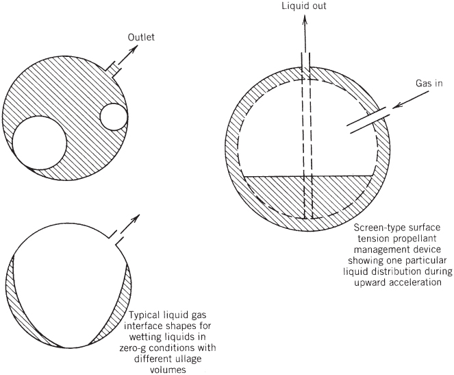
Figure 6–3 Ullage bubbles can float randomly in a zero‐gravity environment; surface tension device are needed to keep tank outlets covered with liquid.

Figure 6–4 Sketches of three concepts of propellant tanks with positive expulsion: (a) inflatable dual bladder; (b) rolling, peeling diaphragm; (c) sliding piston. As the propellant volume expands or contracts with changes in ambient temperature, the piston or diaphragm will also move slightly and the ullage volume will change during storage.
Several basic types of positive expulsion devices have been used successfully in propellant tanks with pressurized feed systems. They are compared in Table 6–2 and shown in Fig. 6–3 for simple tanks. These devices mechanically separate the pressurizing gas from the liquid propellant in the propellant tank. Separation is useful for these reasons:
- It prevents pressurizing gas from dissolving in the propellant and propellant vapors from mixing with the gases. Any dissolved pressurizing gas dilutes the propellant, reduces its density as well as its specific impulse, and makes the pressurization inefficient.
- It allows moderately hot and reactive gases (such as generated by gas generators) to be used for pressurization, thus permitting a reduction in the pressurizing gas system mass and volume. Mechanical separation prevents chemical reactions between hot gases and propellants, prevents any gas from being dissolved in the propellant, prevents propellant vapors from diffusing into the (unheated) pressurant lines and freeze, and reduces the heat transfer to the liquid.
- In some cases, the ullage of tanks containing toxic liquid propellant must be vented without spilling any toxic liquid propellant or its vapor. For example, in servicing a reusable rocket, the tank pressure needs to be relieved without venting or spilling any potentially hazardous materials.
Table 6–2 Comparison of Propellant Positive Expulsion Methods for Spacecraft Hydrazine Tanks
| Selection Criteria | Single Elastomeric Diaphragm (Hemispherical) | Inflatable Dual Elastomeric Bladder (Spherical) | Foldable Metallic Diaphragm (Hemispherical or cylindrical) | Piston or Bellows | Rolling Diaphragm | Surface Tension Screens |
| Application history | Extensive | Extensive | Limited | Extensive in high acceleration vehicles | Modest | Extensive |
| Weight (normalized) | 1.0 | 1.1 | 1.15 | 1.2 | 1.0 | 0.9 |
| Expulsion efficiency | Excellent | Very good | Good | Excellent | Very good | Good or fair |
| Maximum side acceleration | Low | Low | Medium | High | Medium | Lowest |
| Control of center of gravity | Poor | Limited | Good | Excellent | Good | Poor |
| Long service life | Excellent | Excellent | Excellent | Very good | Good | Excellent |
| Preflight check | Leak test | Leak test | Leak test | Leak test | Leak test | None |
| Disadvantages | Chemical deterioration | Chemical deterioration; fits only into a few tank geometries | High‐pressure drop; fits only certain tank geometries; high weight | Potential seal failure; critical tolerances on piston seal; heavy | Weld inspection is difficult; adhesive (for bonding to wall) can deteriorate); bellows have high residuals | Limited to low accelerations |
A piston expulsion device permits the center of gravity (CG) to be accurately controlled, making its location known during engine operation. This is important in rockets with high side accelerations such as anti‐aircraft missiles or space defense interceptor missiles, where the thrust vector needs to go through the vehicle's CG—if the CG is not well known, unpredictable turning moments may be imposed on the vehicle. A piston also prevents sloshing and/or vortexing.
Surface tension devices use capillary attraction for supplying liquid propellant to the tank outlet pipe. These devices (see Fig. 6–3) are often made of very fine (300 mesh) stainless steel wire woven into a screen and formed into tunnels or other shapes (see Ref. 6–5). These screens are located near the tank outlet and, in some tanks, tubular galleries are used designed to connect various parts of the tank volume to the outlet pipe sump. These devices work best in relatively low‐acceleration environments, where surface tension forces can overcome the inertia forces.
The combination of surface tension screens, baffles, sumps, and traps is called a propellant management device. Although not shown in any detail, they are included inside the propellant tanks of Figs. 6–3 and 6–14.
During gravity‐free flights, suddenly accelerated from relatively large thrusts, high forces can be imposed on tanks and thus on the vehicle by strong liquid sloshing motions or by sudden changes in position of the liquid in a partly empty tank. The resulting forces will depend on the tank geometry, baffles, ullage volume and its initial propellant location, and on the acceleration magnitude and direction. Such forces can be large and may cause tank failure.
6.3 PROPELLANT FEED SYSTEMS
Propellant feed systems have two principal functions: (1) to raise the pressure of the propellants and (2) to supply them at design mass flow rates to one or more thrust chambers. The energy for these functions comes either from a high‐pressure gas, centrifugal pumps, or a combination of the two. The selection of a particular feed system and its components is governed primarily by the rocket application, duration, number or type of thrust chambers, past experience, mission and by the general requirements of simplicity of design, ease of manufacture, low cost, and minimum inert mass. A classification of several of the more important types of feed system is shown in Fig. 6–5, and some types are discussed in more detail in other parts of this book. All feed systems consist of piping, a series of valves, provisions for filling and usually also for removing (draining and flushing) the liquid propellants, filters, and control devices to initiate, stop, and regulate their flow and operation. See Ref. 6–1.

Figure 6–5 Design options of feed systems for liquid propellant rocket engines. The more common types are designated with a double line at the bottom of their boxes.
In general, gas pressure feed systems give superior performance to turbopump systems when the vehicle's total impulse or propellant mass is relatively low, the chamber pressure is relatively low, the engine thrust‐to‐weight ratio is low (usually less than 0.6), and when there are repeated short‐duration thrust pulses; here, the usually heavy‐walled propellant tanks and the pressurizing gas constitute the major inert mass of the engine system. In a turbopump feed system, propellant tank pressures are much lower (by a factor of 10 to 40) and thus vehicles' tank masses are much lower (by the same factor). Turbopump systems usually give superior performance when the vehicle's total impulse is relatively large, the chamber pressure is high, and the mission velocity is high.
Local Pressures and Flows
Key parameters for any feed system's description in liquid propellant rocket engines involve flow magnitudes (oxidizer and fuel flow including subsystems and thrust chamber flow passages) together with local pressures (pressurizing gas subsystems). An inspection of the flow diagram of a relatively simple rocket engine with a pressurized feed system, similar to Fig. 1–3, shows that the gas flow splits into two branches, and the propellant flow splits into pipes leading to each of the thrust chambers. The highest pressure resides in the high‐pressure gas supply tank. The pressure drops along the pressurizing gas subsystem (pipes, valves, regulator) and then drops further in the liquid propellant flow subsystems (more pipes, valves, filters, injector, or cooling jacket) as the liquid propellants flow into the thrust chamber, where they burn at the chamber pressure. As shown in Chapter 3, the gas pressure always reaches a minimum at the nozzle exit. It is possible to predict relevant pressure drops and flow distributions when enough information is known about all components and their flow passages. If such analysis can be validated by data from previous pertinent tests, or prior proven rocket engine flights, it will have a higher confidence factor. Most rocket engine design organizations have developed software for estimating pressures and flows at different parts of an engine.
Knowing local flows and the local pressures is important for the following reasons:
- Such information is used in the stress analysis and sometimes in the thermal analysis of related components and subsystems.
- They are needed for rocket engine calibrations so that engines will operate at the intended mixture ratio, chamber pressure, and/or thrust (such tasks are accomplished by using control devices or simple orifices to adjust the pressures). Calibration also requires the proper balance of flows and pressures. For a feed system with one or more turbopumps, such as shown in Fig. 1–4, one needs to also include the rise in pressure as propellants flow through a pump. Furthermore, feed system analyses and calibration with turbopumps become more complex when there are other combustion devices (gas generators or preburners). A more detailed discussion of engine system calibration is given in Section 11.5.
- The measurement of actual flows and key local pressures during engine ground tests (or actual flight operation) and subsequent comparison with predicted values makes it possible to identify discrepancies between practice and theory. Such discrepancies can yield clues to possible malfunctions inadequate designs and/or fabrications, all of which may then be possibly corrected. If actual values can be compared with analysis in real time, some experimental test hardware may be saved from self‐destruction. This can also be the basis for a real‐time engine health monitoring system, which is discussed in Sections 11.5 and 21.3.
Sometimes analyses are done for strictly transient conditions, such as starting or shutdown, or during changes in thrust (throttling). Transient analyses must also provide information for the filling of empty propellant flow passages at different propellant temperatures, for water hammer, valve reaction time, and the like.
6.4 GAS PRESSURE FEED SYSTEMS
One of the simplest and most common means of pressurizing liquid propellants and force them out of their respective tanks is to use a high‐pressure gas. Rocket engines with pressurized gas feed systems can be very reliable. References 6–1, 6–6, and 6–7 give additional information. A rocket engine with a gas‐pressurized feed system was the first to be tested and flown (1926). There are two common types of pressurized feed systems both still used often today.
The first uses a gas pressure regulator in the gas feed line with the engine operating at essentially constant tank pressure and nearly constant thrust. This is shown schematically in Fig. 1–3 and consists of a high‐pressure gas tank, a gas starting valve, a gas pressure regulator, propellant tanks, propellant valves, and feed lines. Additional components, such as filling and draining provisions, check valves, filters, flexible elastic bladders for separating the liquid from the pressurizing gas, and pressure sensors or gauges, are also often incorporated. After all tanks are filled, the high‐pressure gas valve in Fig. 1–3 is remotely actuated and admits gas through the pressure regulator at a constant pressure to the propellant tanks. Check valves prevent mixing of the oxidizer with the fuel, particularly when the unit is not in an upright position. Propellants are fed to the thrust chamber by opening appropriate valves. When the propellants are completely consumed, the pressurizing gas can also be used to scavenge and clean lines and valves of much of the liquid propellant residue. Any variations in this system, such as the combination of several valves into one or the elimination and addition of certain components, depend on the application. If a unit is to be used and flown repeatedly, such as a space‐maneuver rocket, it may include several additional features such as a thrust‐regulating device and a tank level gauge; these will not be found in expendable, single‐shot units, which may not even have a tank‐drainage provision.
The second common type of gas pressure feed system is called a blow‐down feed system. It is shown in Fig. 6–7 and discussed in Refs. 6–7 and 6–8. Here, the propellant tanks are larger because they store not only the propellants but also the pressurizing gas at an initial maximum propellant tank pressure. There is no separate high‐pressure gas tank and no pressure regulator. The expansion of the gas already in the tanks provides for the expulsion of the propellants. Blow‐down systems can be lighter than a regulated pressure system, but gas temperatures, pressures and the resulting thrust all steadily decrease as propellants are consumed. A comparison of these two common types is shown in Table 6–3.
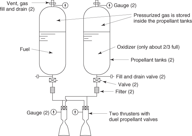
Figure 6–7 Schematic diagram of a typical bipropellant blow‐down pressurized gas feed system with two thrusters.
Table 6–3 Comparison of Two Types of Gas Pressurization Systems
| Type | Regulated Pressure | Blowdown |
| Pressure/thrust | Stays essentially constanta | Decreases as propellant is consumed |
| Gas storage | In separate high‐pressure tanks | Gas is stored inside propellant at tank pressure with large ullage volume (30–60%) |
| Required components | Needs regulator, filter, gas valves, and gas tank | Larger, heavier propellant tanks |
| Advantages | Nearly constant‐pressure feed gives essentially constant propellant flow and approximately constant thrust, Is and r | Simpler system. Less gas required. Can be less inert mass. |
| Better control of mixture ratio | No high‐pressure gas tank | |
| Disadvantages | Slightly more complex | Thrust decreases with burn duration |
| Regulator introduces a small pressure drop | Somewhat higher residual propellant due to less accurate mixture ratio control | |
| Gas stored under high pressure, often for a long time | Thruster must operate and be stable over wide range of thrust values and modest range of mixture ratios | |
| Requires more pressurizing gas | Propellants stored under pressure; slightly lower Is toward end of burning time |
aSee section 6.9 for valves and pressure regulators
Different bipropellant pressurization concepts are evaluated in Refs. 6–1, 6–6, 6–7, and 6–8. Table 6–4 lists various optional features aimed at satisfying particular design goals. Many of these features also apply to pump‐fed systems, which are discussed in Section 6.6. Individual engine feed systems have some but certainly not all of the features listed in Table 6–4. Monopropellants gas pressure feed systems are simpler since there is only one propellant, thus reducing the number of pipes, valves, and tanks.
Table 6–4 Typical Features of Liquid Propellant Feed Systems
| Enhance Safety |
| Check valves to prevent backflow of propellant into the gas tank and inadvertent mixing of propellants inside flow passages. |
| Pressurizing gas should be inert, clean, and insoluble in propellant. |
| Burst diaphragms or isolation valves to isolate the propellants in their tanks and positively prevent leakage into the thrust chamber or into the other propellant tank during storage. |
| Isolation valves to shut off a section of a system that has a leak or malfunction. |
| Sniff devices to detect leak of hazardous vapor in some vehicle compartments or ground test areas. |
| Features that prevent an unsafe condition to occur or persist and shut down the engine safely, such as relief valves or relief burst diaphragms (to prevent tank overpressurization), or a vibration monitor to shut off operation in the case of combustion instability. |
| Provide Control |
| Valves to control pressurization and flow to the thrust chambers (start/stop/throttle). |
| Sensors to measure temperatures, pressures, valve positions, thrust, etc., and computers to monitor/analyze/record system status. Compare measured values with analytical estimates, issue command signals, and correct if sensed condition is outside predetermined limits. |
| Manned vehicle can require a system status display and command signal override. |
| Fault detection, identification, and automatic remedy, such as shutoff isolation valves in compartment in case of fire, leak, or disabled thruster. |
| Control thrust (throttle valve) to fit a desired thrust–time flight profile. |
| Enhance Reliability and Life |
| Fewest practical number of components/subassemblies. |
| Filters to catch dirt in propellant lines, which could prevent valves from closing or might cause small injector holes to be plugged or might cause bearings to gall. |
| Duplication of key components, such as redundant small thrusters, regulators, or check valves. If malfunction is sensed, then often remedial action is to shut down the malfunctioning component and activate the redundant spare component. |
| Heaters to prevent freezing of moisture or low‐melting‐point propellant. |
| Long storage life—use propellants with little or no chemical deterioration and no reaction with wall materials, valves, pipes, gaskets, pressurizing gas, etc. |
| Operate over the life of the mission and its duty cycle, including long‐term storage. |
| Provide for Reusability, If Required |
| Provisions to drain propellants or pressurants remaining after operation. |
| Provision for cleaning, purging, flushing, and drying the feed system and refilling propellants and pressurizing gas. |
| Devices to check functioning of key components prior to next operation. |
| Features to allow checking of engine calibration and leak testing after operation. |
| Access for inspection devices and for visual inspection of internal surfaces or components for damage or failure. Look for cracks in nozzle throat inner walls and in turbine blade roots. |
| Enable Effective Propellant Utilization |
| High tank expulsion efficiency with minimum residual, unavailable propellant. |
| Lowest possible ambient temperature variation and/or matched propellant property variation with temperature so as to minimize mixture ratio change and residual propellant. |
| Alternatively, measure remaining propellant in tanks (using special gauges) and automatically adjust mixture ratio (throttling) to minimize residual propellant. |
| Minimize pockets in the piping and valves that cannot be readily drained or flushed. |
An example of a multi‐thruster liquid propellant rocket engine with an intricate gas pressurized feed system is the MESSENGER (MErcury Surface, Space ENvironment, GEochemistry, and Ranging), Refs. 6–9, 6–10, planetary space probe. Launched on August 3, 2004, this propulsion system enabled two flybys of Venus, and three flybys of the planet Mercury, before going into orbit around Mercury on March 13, 2011. This mission ended in April 2015 when the probe ran out of fuel for the attitude control system that kept the antenna pointed to Earth. A flow diagram is shown in Figure 6–7 and selected data is in Table 6–5 (Refs. 6–9, 6–10). The main bipropellant thruster is identified in the diagram as the LVA (large velocity adjustment)—with nominally 145 lbf thrust; it provided the changes in the flight path; four of the larger monopropellant thrusters (nominally 5 lbf thrust each) provided the pitch and yaw control and four of the 12 smaller monopropellant thrusters provided the roll control (nominally 1 lbf of thrust each) during LVA operation. All 12 small thrusters provided vehicle attitude control whenever needed. As can be seen in Figure 4–14, it requires a minimum of 12 small thrusters to achieve pure torques for vehicle rotation about three mutually perpendicular axes. For very precise rotary orientation, the MESSENGER spacecraft also had a reaction wheel system (see Reaction Control System in Section 4–5). As seen by the dotted lines in Fig. 6–7, there were four modules, each with one MR‐106E and one MR‐111C, all pointing in the same axial direction as the LVA (also called Leros 1b).

Figure 6–7 This schematic of the Liquid Rocket Propulsion System for the MESSENGER Space Probe shows the designed component redundancy and duplication that enhances engine system reliability for many years of use in space. Some diagram abbreviations defined in the text.
Courtesy of Aerojet Rocketdyne and NASA
Table 6–5 Selected Data on the Gas Pressurized Propulsion System of the MESSENGER Space Probe
Data from Refs. 6–9, 6–10
| Designation | Leros‐1b Main Thrust Chamber (M006) | MR‐106E Attitude Control Thrusters | MR‐111C Attitude Control Thrusters |
| Propellant | Hydrazine/N2O4 | Hydrazine | Hydrazine |
| Number of units | 1 | 4 | 12 |
| Thrust chamber cooling | Fuel film cooled and radiation cooled | Radiation cooled | Radiation cooled |
| Thrust (per nozzle) (lbf) | 145 | 6.9‐2.6; Nominal 5 lbf | 1.2‐0.3; nominal 1.0 lbf |
| Feed pressure (psia) | 300‐218 psia | 350‐100 | 450‐50 |
| Chamber pressure, nominal (psia) | 125 nominal | 180‐65 | 200‐35 |
| Vacuum specific impulse (lbf‐sec/lbm) | 318 | 235‐229 | 229‐215 |
| Nozzle area ratio | 150:1 | 60:1 | 74:1 |
| Mixture ratio (oxidizer flow/fuel flow mass ratio) | 0.85 +/– 0.02 | N/A | N/A |
| Minimum burn time (sec) | N/A | 0.016 | 0.015 |
| Maximum burn time (sec) |
2520 (single burn) 20,500 (cumulative) |
2000 (single burn) 4670 (cumulative) |
5000 (single burn) |
| Number of starts, cumulative | 70 | >1000 | >1500 |
| System Parameters | |||
| Oxidizer mass (lbm) | 510 | ||
| Fuel mass (lbm) | 805 | ||
| Pressurant (helium) mass (lbm) | 5.4 | ||
| Propulsion system dry mass (lbm) | 180 | ||
All monopropellant thrusters were radiation cooled and operated in either steady state or pulse modes (as explained below), and most had redundant valve seats for protection against leakage and an inlet filter to keep particulate away from the valve seats. The propulsion system of Fig. 6–7 shows two hydrazine fuel tanks (FT#1 and FT#2), one oxidizer tank (OT), one high‐pressure helium (GHe) tank, redundant check valves, filters, latch valves,2 pyrotechnic isolation valves, service valves, redundant temperature sensors and redundant pressure sensors (redundant here means if one malfunctions, its reading can be ignored—this improves reliability). There is also a small, spherical, positive expulsion auxiliary fuel tank (AFT) with a flexible diaphragm separating the helium gas and the propellants. It was used to start four of the small monopropellant thrusters (firing in a direction parallel to the LVA thruster) in the gravity‐free space environment. Their acceleration would cause the liquids in the three main tanks to be oriented and cover the respective tank outlets with propellant. This maneuver avoided letting helium gas from the tanks enter the thruster. It is known that gas bubbles being supplied to an operating thruster may cause uncontrolled and irregular thrust and in bipropellants, bubbles can also initiate destructive combustion instability, so any inadvertent feeding of gas to the thrusters must be avoided. The auxiliary tank was refilled with propellant from the main tanks during some of the axial maneuvers which enabled propellant availability for propellant settling just before the next maneuvers.
Not shown in Fig. 6–7 is the electric subsystem (heaters, switches, valve position indicators, controllers, etc.). Electrical heaters were provided on all components and propellant lines which were exposed to hydrazine to prevent freezing in the space environment. Care was taken to make sure locations where hydrazine vapor might migrate were also heated. A catalyst bed temperature of at least 250 °F allowed faster catalyst reactions and provided longer catalyst bed lifetimes.
Some of the MESSENGER vehicle maneuvers require axial thrust, which is lower than that provided by the LVA thruster (145 lbf nominal). This can be achieved by operating the four MR‐106E thrusters (nominally 5 lbf each for a total of 20 lbf of thrust) together with the four MR‐111C (nominally 1 lbf of thrust each) in the same module for pitch and yaw control. The MESSENGER rocket propulsion system has series‐redundant gas pressure regulators for each propellant and operates most of the time with a nearly constant flow gas pressure feed system; however, for parts of the operation it also operates in a blow‐down pressurization mode. The small auxiliary fuel tank can be recharged with hydrazine from the main fuel tanks during flight.
Pulsing of thrusters is common in small monopropellant units. A short thrust period (typically 15 to 100 milliseconds) is followed by a period of no thrust (typically 15 to 300 milliseconds), and this can be frequently repeated. An ideal simple thrust profile is shown in Problem 6–3. One merit of pulsing the thrust is the ease for changing the total impulse to fit particular flight maneuvers by changing the number of pulses; alternatively one can change the pulse duration or change the time between pulses. Also pulsing valves are less costly than throttling valves. The disadvantage of pulsing, when compared to continuous nonpulsing operations of the same peak thrust, is a decrease of specific impulse and that requires more propellant usage and lengthens the operation duration. A cluster of thrusters (e.g., the four MR‐106L thrusters in Fig. 6–7) can also be “off‐pulsed” to balance the spacecraft. In this case, the thruster with the lowest thrust (or with the least influence on the spacecraft's position) will fire at steady state and the other thrusters will turn off for varying amounts of time in order to guide the spacecraft in the commanded direction.
Compartmented propellant metal tanks with anti‐slosh and anti‐vortex baffles, sumps, and a surface tension propellant retention device allow propellant to be delivered independent of the propellant load, the orientation, or the acceleration environment (some of the time in zero‐g). Gauges in each tank allow a determination of the amount of propellant remaining, and they also indicate leaks. Safety features can include sniff lines at each propellant valve actuator to sense leakage. With cryogenic propellants electrical heaters are provided at propellant valves, certain lines, and injectors to prevent fuel freezing or moisture turning into ice.
Some pressure feed systems can be prefilled with storable propellant and pressurizing agent at the factory and stored in readiness for operation. Compared to solid propellant rocket units, these prepackaged liquid propellant pressurized feed systems offer advantages in long‐term storability, random restarts, and better resistance to transportation vibration or shock.
Thrust levels in rocket propulsion systems are a function of propellant flow magnitudes which in pressurized gas feed systems are governed by the gas pressure regulator settings. The propellant mixture ratio in this type of feed system is a function of the hydraulic resistance of the liquid propellant lines, cooling jacket, and injector, and the mixture ratio is usually adjusted by means of variable restrictors or fixed orifices. Further discussion of the adjusting of thrust and mixture ratio can be found in Sections 11.5 and 11.6 and in Example 11–2.
6.5 TANK PRESSURIZATION
As stated earlier, the objective of feed systems is to move propellants under pressure from propellant tanks to thrust chamber(s). The tank pressurization system is that part of the feed system that provides such a propellant expellant gas. See Refs. 6–1, 6–6, 6–7, and 6–10. As was described in Section 6.3, there are two types: (1) in a pressurized gas feed system, a relatively high‐pressure gas displaces the propellants from the tanks, and (2) in a pumped feed system (described in the next section) the main energy for feeding the propellants comes from one or more pumps. It requires lower gas pressures in the tanks to move the propellants to the pump inlet, and it helps to avoid pump cavitation.
There are several sources of pressurizing gas used in tank pressurization systems.
- High‐pressure inert gases stored at ambient temperature are the most common. Typical gases are helium, nitrogen, and air. Table 6–3 shows a comparison of the regulated pressure system (see Fig. 1–3) and the blow‐down system (see Fig. 6–7). This is discussed further in this section. When gases expand adiabatically, their temperature drops.
- Heated high‐pressure inert gases (typically 200 to 800 °F or 93 to 427 °C) reduce the amount of required gas and thus the inert mass of the pressurizing system. Examples are gases heated by a heat exchanger with the warm exhaust from a gas generator or a turbine or with electrical heaters inside the gas tank.
- Gases created by a chemical reaction using either liquid bipropellants or a monopropellant, or alternatively a solid propellant, all at mixture ratios or compositions that result in “warm gas.” Uncooled hardware can be used. The term warm gas (say 400 to 1600 °F or 204 to 871 °C) distinguishes such gas from the “hot gas” (4000 to 6000 °F, or 2204 to 3319 °C) in the main combustion chamber. Chemically generated warm gases usually result in tank pressurization systems lighter than heated inert gas systems, particularly for high total impulse applications. These gases may also come from two separate small gas generators for tank pressurization—one produces fuel‐rich gas for pressurizing the fuel tank and the other feeds oxidizer‐rich pressurizing gas into the oxidizer tank. Such a scheme was first used in the United States on the Bomarc rocket engine around 1952 and in the Russian RD‐253 around 1961. Another common warm‐gas scheme has been to bleed a small amount of warm gas from the engine's gas generator or preburner. If such a gas is fuel rich, then it can only be used for pressurizing the fuel tank, and it may need to be cooled. Chemical reaction gases are typically at 1200 to 1700 °F or 649 to 921 °C, a range within the gas temperatures allowable for most alloy turbines and steel tanks. Catalyzed decomposed hydrazine products have successfully pressurized liquid hydrazine tanks. With aluminum propellant tanks it is often necessary to cool the warm gas further; many aluminum alloys melt around 1100 °F (593 °C). This gas cooling has been accomplished using a heat exchanger with one of the propellants. Solid propellant gas generators have been used in experimental liquid propellant rocket engines, but to date none are known to have been adapted for a production flight vehicle. One clever system developed in the former Soviet Union uses two rocket engines operating simultaneously on the same vehicle. The larger engine has bleeds gases from an oxidizer‐rich preburner to pressurize a common oxidizer tank. The second engine feeds four smaller hinge‐mounted vernier thrust chamber used for attitude control and also for extra thrust; their fuel‐rich gas generator has a bleed of gas for pressurizing the common fuel tank. Ref. 6–11.
- Evaporated flow of a small portion of a cryogenic liquid propellant, usually liquid hydrogen or liquid oxygen, by applying heat from a thrust chamber cooling jacket or from turbine exhaust gases (with heat exchangers), and then using a part or all of this evaporated flow for tank pressurization. Orifices or pressure regulators may be needed for attaining the desired tank pressure and mass flow rates. This scheme was used for the fuel tank of the Space Shuttle Main Engine (now the RS‐25 engine), and the tap‐off stub for pressurizing gas can be seen later in Fig. 6–11 at the turbine exhaust manifold of the fuel booster pump. The oxygen tank was pressurized by gasified liquid oxygen, which was tapped off the discharge side of the main oxygen pump and heated in a heat exchanger around the turbine of the main oxygen pump, as shown in Figure 6–11.
- Direct injection of a small stream of hypergolic fuel into the main oxidizer tank and a small flow of hypergolic oxidizer into the fuel tank has been tried by several countries but with limited success. It is really another form of chemical gas generation.
- Self‐pressurization of cryogenic propellants by evaporation is feasible but can be difficult to control. Experience here is limited.
In order to design or analyze any pressurizing system it is necessary to have relevant information about the tank and the engine. This can include basic engine parameters, such as propellant flow, thrust, duration, pulse width, propellant tank volume, percent ullage of tank volume, storage temperature range, propellant and pressurizing gas properties, propellant tank pressure, gas tank pressure, and/or amount of unavailable residual propellant. For many of these items, nominal, maximum, and minimum values may be needed.
Factors Influencing the Required Mass of Pressurizing Gas
A key task in the analysis and design of tank pressurization systems is determining the required mass of pressurizing gas. Many different factors influence this mass, and some of them can be quite intricate, as shown in Ref. 6–1. The gaseous mass may be estimated using simplifying assumptions, but it is always more accurate when based on actual test results and/or data from similar proven pressurizing systems. Following are some influencing factors that should be accounted for:
- Evaporation of propellant at the interface between the pressurizing gas and the liquid propellant is a key phenomenon. The evaporated propellant dilutes the gas and changes its expansion properties. This change depends on the temperature difference between the gas and the liquid, sloshing, vapor pressure of the propellant, turbulence, and local gas impingement velocities. Furthermore, any propellant film on those portions of the tank walls and baffles that are above the liquid level will also evaporate. “Warm gases” (e.g., a bleed from a gas generator) will heat the top layer of the liquid propellant and increase propellant evaporation reducing its local density. Because with cryogenic propellants the gas is always warmer than the liquid, as the gas cools, more liquid evaporates.
- The temperature of those propellant tank walls which form part of exterior vehicle surfaces exposed to the atmosphere are affected by aerodynamic heating, which may vary during flight. Such heating can increase the gas temperature as well as the liquid propellant temperature, augmenting liquid evaporation.
- The solubility of a gas in a liquid is affected by temperature and pressure. For example, because nitrogen gas is soluble in liquid oxygen, it requires approximately four times as much nitrogen gas to pressurize liquid oxygen as an equivalent volume of water. This dilutes the oxygen and causes a small performance loss. Helium is a preferred pressurant gas because it is least soluble in liquid oxygen.
- Condensation of certain gaseous species can dilute the propellant. The water vapor in warm gases is an example. Condensation can also occur on the exposed wetted inner walls of propellant tanks, and this requires more pressurizing gas.
- Changes in the gas temperature may take place during operation. Compressed gases undergoing an adiabatic expansion can cause noticeable gas cooling; temperatures as low as 160 to 200 K (−228 to –100 °F) have been recorded with helium. A cold gas will absorb heat from the propellants and the engine hardware. The particular nature of the expansion process will depend largely on the time of rocket operation. For large liquid propellant rocket engines, which run only for a few minutes, the expansion process will be close to adiabatic, which means little heat transfer from the hardware to the gas. For satellites, which stay in orbits for years and where the thrusters operate only occasionally and for short operating periods, heat will be transferred from the vehicle hardware to the gas, and expansion will be close to isothermal (no change in temperature).
- Chemical reactions in some species of pressurizing gas with the liquid propellant have occurred, some that can generate heat or increase the pressure. Inert gases, such as helium, undergo no chemical reactions with propellants.
- Turbulence, impingement, and irregular flow distributions of the entering gas will increase the heat transfer between the liquid and the gas. Depending on the temperature difference, it can cause additional heating or cooling of the top liquid layers.
- Vigorous sloshing can quickly change the gas temperature. In some of the experimental flights of the Bomarc missile, side accelerations induced sloshing, which caused a sudden cooling of the warm tank pressurizing gas and resulted in a sudden reduction of tank pressure and propellant flow. See Refs. 6–4 and 6–5.
- In many rocket engines, a portion of the pressurizing gas is used for purposes other than tank pressurization, such as actuation of valves or controls. The amount required, once determined, must be added to the total gas mass needed.
Simplified Analysis for the Mass of Pressurizing Gas
This section describes the case of a pressurizing system using a compressed gas stored initially in a separate tank at ambient temperatures. It is the first category of pressurizing systems discussed above and perhaps the most common type. When the tank has some insulation and the operation of the rocket engines is relatively short (1 or 2 minutes), the expansion process in the gas tank is close to adiabatic (i.e., no heat transfer to or from the system hardware and the gas expansion in the storage tank noticeable drops the gas temperature and changes its density). At the other extreme is the isothermal expansion; a considerably slower process requiring longer times for temperature equilibration, an example being many short operations in a multi‐year orbit maintenance. We may assume here perfect gas behavior, where perfect gas formulations apply (see Chapters 3 and 5). Furthermore, we assume no evaporation of the liquid propellant (only valid for propellants with low vapor pressure), an inert pressurizing gas that does not dissolve in the liquid propellant, and that no propellant sloshing or vortexing occurs.
Let the initial condition in the gas tank be given by subscript 0, the final gas conditions in the gas tank by subscript g, and the gas in the propellant tank by subscript p; final pressures may differ because in practice ![]() to account for valve, piping, and regulator pressure drops. The relevant equations include mass continuity and the perfect equation of state as shown below:
to account for valve, piping, and regulator pressure drops. The relevant equations include mass continuity and the perfect equation of state as shown below:
Here, V represents the gas volume (m3 or ft3). When the end points of the process of propellant displacement are isothermal (a relatively slow process), then the temperatures before and after will be the same (and heat will be drawn from the environment). Substituting the gas law into the mass balance and solving for V0, after T0 equilibrates,
Now, returning to Eqs. 6–5 we arrive at the total gas mass m0,
In real pressurizations, end conditions should fall somewhere between isothermal and adiabatic. In thermodynamics, a reversible‐adiabatic process is isentropic so that here we may speak of a reversible “polytropic expansion” of a perfect gas, where the polytropic exponent lies between 1.0 and k. Example 6–2 provides a set of tank volume and total mass estimates using either helium or nitrogen as the pressurizing gas.
6.6 TURBOPUMP FEED SYSTEMS AND ENGINE CYCLES
The principal components of a rocket engine with one type of turbopump system are shown in the simplified diagram of Fig. 1–4. Here, the propellants are pressurized by means of separate pumps, which in turn are driven by one or more turbines. These turbines derive their power from the expansion of high enthalpy gases.
Figures 10–1, 10–2, and 10–3 show turbopump examples, and Chapter 10 is devoted exclusively to this topic. The turbopump is a high‐precision, accurately balanced piece of high‐shaft‐speed (rpm) rotating machinery. It consists usually of one or two centrifugal pump(s) and a turbine. Its high‐speed, high‐load bearings support the shaft(s) on which the pump impeller(s) and turbine disk are mounted. It has shaft seals to prevent propellant leakage and also to prevent the two propellants from mixing with each other inside the turbopump. Some turbopumps also have a gear transmission, which allows the pumps or turbine to rotate at different, usually more efficient, shaft speeds. Chapter 10 describes the design of turbopumps and their major components, several arrangements of the key components, and alternate configurations. Starting turbopump feed systems usually takes longer than pressurized feed systems, because it takes some time for the rotating components (pumps, turbines) to accelerate to operating shaft speeds. Starting is discussed in Sections 7.1 and 11.4.
Engines with turbopumps are preferred for the booster and sustainer stages of space launch vehicles, long‐range missiles, and in the past also for aircraft performance augmentation. These feed systems include the tanks, and they are usually lighter than other types for such high‐thrust, long‐duration applications (the inert hardware mass of the rocket engine without tanks is essentially independent of duration). From turbopump feed system options, such as depicted in Chapter 10, the designer can select the most suitable concept for any particular application.
In summary, turbopump feed systems are usually preferred when the engine has a relatively high total impulse, which usually means high thrust and/or very long cumulative firing duration. Pressurized feed systems are best for rocket engines with relatively low total impulse, that is, low thrust and/or many multiple starts.
Engine Cycles
All liquid propellant rocket engines with a turbopump feed system operate with one of several engine cycles. The three most common are shown in Fig. 6–8, and they have flown many times. Reference 6–12 shows variations of these three cycles and other engine cycles, some of which have not yet flown and some have not yet even been built.

Figure 6–8 Simplified diagrams of three common engine cycles for liquid propellant rocket engines. The spirals are a symbol for an axisymmetric cooling jacket where heat is absorbed.
An engine cycle for turbopump‐fed engines consists of (1) specific propellant flow paths through the major engine components, (2) a method for providing the hot gas to one or more turbines, and (3) a method for handling the turbine exhaust gases. There are two types of operating cycle, open and closed cycles. Open denotes that the working fluid coming from the turbine is discharged into the nozzle exit section of the thrust chamber at a location in the expanding section far downstream of the nozzle throat as shown schematically in Fig. 6–8 (and discussed in Table 6–6), or is discharged overboard, usually after having been expanded in a separate nozzle of its own as in Figs. 1–4 and in 6–9a and 6–9b. In closed cycles or topping cycles all the working fluid from the turbine is injected into the rocket engine combustion chamber to use more efficiently its remaining energy. Here, the turbine exhaust gas is fed into the injector of the thrust chamber and is expanded through the full pressure ratio of the main thrust chamber nozzle, thus giving a somewhat higher performance than the open cycles, where these exhaust gases expand only through a relatively small pressure ratio.
Table 6–6 Qualitative Characteristics for Three Different Engine Cycles
| Engine Cycle | Gas Generator Cycle | Expander Cycle | Staged Combustion Cycle |
| Engine specific impulse, as % of gas gen. cycle | Set to 100% | 102–106% | 102–108% |
| Turbine flow, as % of total | 1.5–7% | 75–96% of the fuel flow or | 60–80% |
| propellant flow | 12–20% of total | ||
| Typical pressure drop, across turbine as % of chamber pressure | 50–90 | 5–30 | 60–100 |
| Propellant type | All types | Cryogenic fuel for cooling | All types |
| Pump discharge pressure, % of chamber pressure | 135–180 | 150–200 | 170–250 |
| Turbine exhaust gas | Dumped overboard through a | Fed into main thrust | Fed into main thrust |
| separate nozzle or aspirated | chamber injector | chamber injector | |
| into main nozzle exit section | |||
| Relative inert mass of engine | Relatively low | Higher | Highest |
| Thrust control, typical | Regulate flow and/or mixture | Regulate bypass of some gasified | Regulate preburner mixture |
| ratio in gas generator | fuel flow around turbine | ratio and propellant flows | |
| Maximum pressure in feed system | Relatively low | Higher | Highest |
| First ground tests | Goddard, USA, 1934 | Aerojet‐Rocketdyne, 1960 | RNIIa, Russia, 1958 |
| First flight operation | Hellmuth Walter Comp., | Aerojet‐Rocketdyne, 1963 | Korolev Design Bureau, 1961 |
| Germany, 1939 |
a Rossiyskiy Naucho Isseldovatelskiy Institut (Reaction Propulsion Research Institute).

Figure 6–9a Large RS‐68 rocket engine with a gas generator cycle. For engine data, see Table 11–2.
Courtesy of Aerojet Rocketdyne

Figure 6–9b Simplified flow diagram of the RS‐68. It identifies major components and includes valves, propellant feed ducts, turbine exhaust ducts, small sized tubing for drains, purges, hydraulic controls, and it shows the pipe for helium spin‐up of the turbines for starting. The circled numbers are explained on that page. Some of the small tubing is not shown in full length; only the first and last few inches are shown.
Courtesy of Aerojet Rocketdyne
Table 6–6 shows key parameters for each of the three common cycles, and it describes the differences between them. The schematic diagrams of Fig. 6–8 show each cycle with a separate turbopump for fuel and for oxidizer. However, arrangements where the fuel and oxidizer pump are driven by the same turbine are also common because sometimes such schemes reduce the hardware mass, volume, and cost. The “best” cycle needs to be selected on the basis of mission, suitability of existing engines, and criteria established for each particular vehicle. There is an optimum chamber pressure and an optimum mixture ratio for each application and for each engine cycle, both of which depend in part on optimization factors such as maximum range, lowest cost, and/or highest payload.
The gas generator cycle has been the most commonly used. Compared to other engine cycles, its rocket engines are relatively simple, pressures are usually lower, and generally they have a lower inert mass and engine cost. However, its performance (specific impulse) is less by a few percentage points than the other two cycles. Such performance is nevertheless adequate for many space flight and military missions.
In gas generator cycles, the turbine inlet gas comes from a separate gas generator, whose propellants can be supplied from two separate pressurized propellant tanks or can be drawn off main propellant pump discharges. Some early engines also used a separate monopropellant for creating the generator gas; the German V‐2 missile engine used hydrogen peroxide decomposed by a catalyst. Typically, turbine exhaust gases are discharged overboard through one or two separate uncooled ducts and small low‐area‐ratio nozzles (at relatively low specific impulse), as shown schematically in Fig. 1–4 and in the Vulcain engine or RS‐68 engine (Figs. 6–9a and 6–9b and listed in Table 11–2). Alternatively, this turbine exhaust can be aspirated into the main flow through multiple openings in the diverging nozzle section, as shown schematically in Fig. 6–8 for a gas generator engine cycle. This turbine exhaust gas then can protect the diverging walls near the nozzle exit from high temperatures. Both methods can only provide small amounts of additional thrust. The gas generator mixture ratio is usually fuel rich so that the gas temperatures are low enough (typically 900 to 1350 K) to allow the use of uncooled turbine blades and uncooled nozzle exit segments.
The liquid‐oxygen/liquid‐hydrogen RS‐68 rocket engine, shown in Figs. 6–9a and 6–9b, is an example of an engine operating on a gas generator cycle. See Refs. 6–13, 6–14, and 6–15. Three RS‐68 engines are used on the Delta IV Heavy launch vehicle; one propels the first or center stage of the vehicle, and the others propel each of the two strap‐on outboard stages, as seen in Fig. 1–12. Data from this engine is under Fig. 6–9a and in Table 11–2. With a gas generator cycle the specific impulse of the thrust chamber by itself is always somewhat higher (by one‐half to 4%) than the specific impulse of the engine. This difference is due to the small turbine exhaust flow with its very low specific impulse, making the overall thrust of the rocket engine always just a little larger in gas generator cycles. This engine is started by flowing helium (from a ground‐based tank) through the gas generator pumps and turbines. The helium flow also purges any air initially in the engine passages and thus prevents any freezing of air and/or moisture. Each engine has two separate turbopumps (see Chapter 10) to raise the pressure and control the flow of propellants that feed the thrust chamber (see Chapter 8). Not shown in the RS‐68 flow diagram are (a) thrust vector control components, which change angular thrust directions, such as a gimbal mounting block on top of the injector and two hydraulic actuators (see Chapter 18), (b) the ignition system (see Section 8.6), (c) electrical subsystems (wires, sensors, switches) and (d) the separate power supply for providing a high‐pressure hydraulic fluid. This pressurized hydraulic fluid energizes (through two actuators) the engine's angular motion and the movable roll control nozzle (which uses exhaust gases from the fuel turbine), it is also used for operating and throttling the four principal valves. Flexible joints in the high‐pressure propellant ducts and the exhaust ducts are both needed to allow for angular motion of the engine and for thermal growth. There is usually an intentional leak of propellant at the rotary seals of the turbopumps and at the stems of major valves, and the diagram shows drains for the safe discharge of such leaks; these small leaks allow for seal cooling and lubrication. The heat exchanger shown in the flow diagram gasifies a small flow of liquid oxygen used to pressurize the liquid oxygen tank during flight at low tank pressures. The hydrogen tank is pressurized by a small gaseous hydrogen flow from the exit of thrust chamber cooling jacket after reducing its pressure. The nozzle exit section of the thrust chamber is uncooled and internally lined with an ablative high‐temperature material; the combustion chamber and nozzle throat section are regeneratively cooled by liquid hydrogen in the cooling jacket (see heat transfer in Chapter 8). Just before start, the engine's liquid propellant passages are brought to a very low temperature by periodically bleeding cryogenic propellant—down to the main propellant valves. Such drastic cooling is simultaneous with the loading and pressurization of propellants into the vehicle. Thrust in the RS‐68 can be throttled to 60% of full value and this is needed during ascent to reduce acceleration and avoid high aerodynamic pressures on the vehicle at certain altitudes. See Refs. 6–11 and 6–12.
The RS‐68 engine has recently been replaced with a simplified version (RS‐68A) having a somewhat higher thrust and chamber pressure. Some of its parameters are: thrust 797,000 lbf (vacuum) and 702,000 lbf (sea level), mixture ratio 5.97, chamber pressure 1,557 psia, specific impulse 411 sec (vacuum) and 362 sec (sea level), nozzle exit area ratio 21.5, and engine weight a sea level 14,770 lbf.
The expander cycle and the staged combustion cycle are both closed cycles, and any small improvement they offer makes a substantial difference in payloads for flight missions with high mission velocities. Alternatively, they allow somewhat smaller flight vehicles. However, these engines are usually more complex, heavier, and more expensive.
A flow diagram of an expander cycle is shown in Fig. 6–10. The preferred fuel for this cycle is cryogenic hydrogen. It is evaporated, heated, and then fed to low‐pressure‐ratio turbines after having passed through the engine's cooling jackets. Part of the coolant, perhaps 5 to 15%, bypasses the turbine (as shown in Fig. 6–10) and rejoins the turbine exhaust flow before the entire coolant flow is sent to the injector or into the engine combustion chamber. Advantages of the expander cycle include good specific impulse, no gas generator, and a relatively low engine mass. In an expander cycle, all the propellants are fully burned in the engine combustion chamber and efficiently expanded in the exhaust nozzle of the thrust chamber.

Figure 6–10 Schematic flow diagram of the RL10B‐2 upper‐stage rocket engine is an example of an expander engine cycle.
Courtesy of Aerojet Rocketdyne

Figure 6–11 Flow diagram illustrating the staged combustion cycle of both the Space Shuttle Main Engine (SSME) and the RS‐25 engine which use liquid oxygen and liquid hydrogen fuel.
Courtesy of Aerojet Rocketdyne and NASA
An expander cycle is used in the RL10 hydrogen/oxygen rocket engine and different versions of this engine have flown successfully in the upper stages of several space launch vehicles. Data on the RL10 engines are given in Tables 6–6, 8–1, and 11–2, Section 6.8 and Ref. 6–16. A modification of this engine, the RL10B‐2 with an extendible nozzle skirt, can be seen in Fig. 8–17. The turbine drives a single‐stage liquid oxygen pump (through a gear case) and a direct drive for a two‐stage liquid hydrogen pump. Cooling down of the hardware to cryogenic temperatures is accomplished by flowing (prior to engine start) cold propellant through the engine by opening “cool‐down valves.” Pipes for discharging the cooling propellants overboard are not shown here but can be seen in Fig. 8–17. Thrust is regulated by controlling the flow of hydrogen gas to the turbine, bypassing the turbine to maintain constant chamber pressure. Helium is used for a power boost, actuating several of the larger valves through solenoid‐operated pilot valves.
In staged combustion cycles, the coolant flow path through the cooling jacket is the same as that of the expander cycle. But here, a preburner (a high‐pressure gas generator) burns all the fuel with part of the oxidizer to provide high‐enthalpy gas to the turbines. The total turbine exhaust gas flow is then injected into the main combustion chamber where it burns with the remaining oxidizer. This cycle lends itself to high‐chamber‐pressure operations that permit a relatively small thrust chamber size. The extra pressure drop in the preburner and turbines causes the pump discharge pressures of both the fuel and the oxidizer to be higher than with open cycles, requiring heavier and more complex pumps, turbines, and piping. Turbine flows can be relatively high and turbine pressure drops low, when compared to other cycles. Staged combustion cycles give high specific impulses, but their engines are more complex and massive. A variation of the staged combustion cycle was used in the Space Shuttle main engine, now modified to the RS‐25, as shown in Figs. 6–1 and 6–11. This engine actually used two separate preburner chambers, each mounted directly on a separate main turbopump. In addition, there were two more low‐speed, low‐power turbopumps for providing boost pressures to the main pumps, but their turbines were not driven by combustion gases; instead, high‐pressure liquid oxygen drove one booster pump and evaporated hydrogen drove the other.
The Russians have flown more than 10 different staged‐combustion cycle rocket engines, all of which use an oxidizer‐rich preburner. The Japanese and also the Chinese have also flown their own oxidizer‐rich designs of this cycle. The United States' version of this cycle with a fuel‐rich preburner was found in the Space Shuttle Main Engine (or RD‐25 engine). If there is a leak in the oxidizer‐rich gas portion of the engine, the leaking gas will not ignite with air unlike any hot fuel‐rich leaks that will readily ignite with air causing engine fires. There are some disadvantages in oxidizer‐rich systems related to pump power—because there is more oxidizer pressure being handled, higher pump powers are required at the preburner or turbine inlets than with fuel‐rich systems where all the fuel is pumped to the higher pressures (pump efficiencies do improve at the larger oxidizer flows and higher pressures). A fuel‐rich staged combustion engine cycle (the RS‐25) can be seen in Fig. 6–11, a simplified diagram of which can be found in Fig. 6–8; an oxidizer‐rich cycle is shown later in Fig. 6–13 (the RD‐191).
The Russian RD‐191 liquid propellant rocket engine (developed and built by NPO Energomash) is another example of a staged combustion cycle (Ref. 6–11 and 6–12). One, three, or five of these engines are used to power the first and strap‐on stages of several versions of the new Angara fleet with different sizes of Russian space launch vehicles. See Figs. 6–12 and 6–13, Table 6–7, and Refs. 6–11 and 6–17. This engine is a single thrust chamber derivative of both the RD‐170 (with four thrust chambers, which is no longer in production) and the RD‐180 (two thrust chambers, used in the Atlas 5). It has an oxidizer‐rich preburner, a two‐axis gimbal mount, an essentially identical thrust chamber to its predecessors, and a turbopump with a 2‐stage turbine, an oxidizer pump, a fuel pump and a second fuel pump feeding the high‐pressure preburner. The more powerful main turbopump has one liquid oxygen pump and two fuel (kerosene) pumps, one of which is a smaller kick pump (small flow second stage – higher discharge pressure). Two lower‐speed booster turbopumps (one for the liquid oxygen and one for the kerosene) slightly raise the propellant pressure to avoid cavitation in the impellers of the main pumps. See Section 10.5. A portion of the warm turbine exhaust gas is used in a heat exchanger to heat and expand the helium that is used to pressurize the propellant tanks in the flight vehicle. Not shown in Fig. 6–13 is a bleed for a portion of the high‐pressure fuel (from the pump discharge) that drives two hydraulic actuators of the gimbal‐mounted thrust chamber for thrust vector control. In Section 10.8 there is a discussion of fuel rich and oxidizer rich gases that come from preburners.
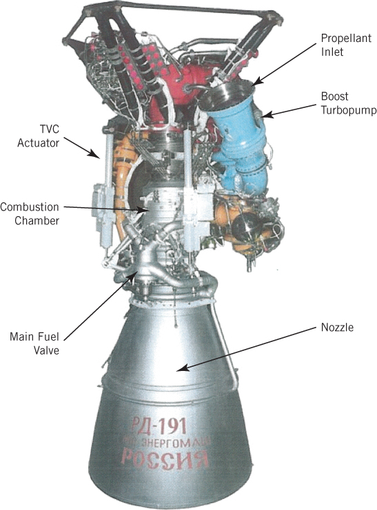
Figure 6–12 Russian RD‐191 liquid propellant rocket engine. This is a relatively new engine that operates on a staged combustion cycle.
From NPO Energomash, Khimki, Russia

Figure 6–13 Simplified RD‐191 flow diagram. See Figure 8–11 for a sectioned view of the thrust chamber and Figure 8–4 12 for a sectioned view of the injector
From NPO Energomash, Khimki, Russia

Figure 6–14 Schematic flow diagram of a helium‐pressurized, bipropellant rocket engine system for the fourth stage of the Peacekeeper ballistic missile, which provides the terminal velocity (in direction and magnitude) to each of several warheads. It has one large gimbaled thrust chamber for trajectory translation maneuvers and eight small thrusters (with scarfed nozzles) for attitude control in pitch, yaw, and roll. For clarity, the tanks and feed system are shown outside the vehicle skin though they are located within.
Courtesy of USAF
Table 6–7 Selected Performance and Operational Characteristics of the RD‐191 Engine
From NPO Energomash, Khimki, Russia
| Number of thrust chambers per engine | 1 |
| Thrust, sea level, and vacuum, kN | 1921 and 2084 |
| Specific impulse, sea level, and vacuum, sec | 310.8 and 337.9 |
| Mixture ratio,a oxygen/kerosene flow | 2.63 ± 7% |
| Chamber pressure (at injector face), MPa | 25.813 |
| Engine, dry mass, kg | 2200 |
| Engine mass with propellants, kg | 2430 |
| Thrust chamber internal diameter, mm | 380 |
| Throat diameter, mm | 235.5 |
| Nozzle exit area ratio | 36.87 |
| Engine, maximum‐height and diameter, mm | 3780 and 1930 |
| In‐flight operating time (nominal), sec | 250 |
| Throttling range, % | 100 to 70 |
| Gimbal angle, typical, degrees | 3.5 |
aLiquid oxygen/Russian kerosene (similar to RP‐1).
6.7 ROCKET ENGINES FOR MANEUVERING, ORBIT ADJUSTMENTS, OR ATTITUDE CONTROL
These engines usually include a set of small thrusters that are installed at various places in a vehicle and a common pressurized feed system, similar to Figs. 1–3, 4–14 and 6–14. They are called reaction control systems, auxiliary rocket propulsion systems, or attitude control systems in contrast to higher‐thrust primary or boost propulsion systems. Most have multiple small thrusters, produce low thrust, use storable liquid propellants, and require accurate repeatable pulsing, a long life in space and/or long‐term storage with loaded propellants in the flight tanks. Typical thrust levels in small thruster are between 0.1 and 1000 lbf (0.445 and 4,448.2 N). Figure 4–14 indicates that 12 thrusters are required for the application of pure torques about three vehicle axes. If three‐degree‐of‐freedom rotations are not needed, or if torques can be combined with some translation maneuvers, fewer thrusters will be required. Such auxiliary rocket engines are commonly used in spacecraft and missiles for accurate control of flight trajectories, orbit adjustments, or attitude control of the vehicle. References 6–1 and 6–17 give information on several of these maneuvers and on small‐thruster history. Figure 6–14 shows a simplified flow diagram for a postboost control rocket engine, with one larger rocket thrust chamber for changing the velocity vector and eight small thrusters for attitude control.
Section 4.5 describes various space trajectory correction maneuvers and satellite station–keeping maneuvers that are typically performed by these small auxiliary liquid propellant rocket engines with multiple thrusters. Table 6–8 lists typical applications for rocket engines with small thrusters.
Table 6–8 Typical Applications for Small Thrusters
Source: Mostly from Ref. 6–17.
| Flight path (or orbit) corrections or changes: |
| Minor flight velocity adjustments |
| Orbit station keeping (correcting for deviations from orbit), or orbit maintenance |
| Orbit injection for small satellites |
| Deorbit maneuver for satellites |
| Divert and other maneuvers of terminal interceptor stages |
| Flight path control of some tactical missiles |
| Attitude control for: |
| Satellites, stages of space launch vehicles, space stations, missiles |
| Roll control for a single gimbaled larger rocket engine |
| Pointing/orienting antennas, solar cells, mirrors, telescopes, etc. |
| Correct the misalignment of principal, larger thrust chamber |
| Velocity tuning of warheads (postboost control system) for accurate targeting |
| Settling of liquid propellants in tanks prior to gravity‐free start of main engine |
| Docking/rendezvous of 2 space vehicles with one another |
| Flywheel desaturation |
Attitude control can be provided during two occasions, while a primary propulsion system (of a vehicle or of a stage) is operating and while its small thruster rocket system operates by itself. For instance, this is done to point satellite's telescope into a specific orientation or to rotate a spacecraft's main thrust chamber into the desired direction for a vehicle turning maneuver.
A common method for achieving accurate velocity corrections or precise angular positions is to operate (fire) some of the thrusters in a pulsing mode (e.g., fire repeatedly for 0.010 to 0.020 sec, each time followed by a pause of perhaps 0.020 to 0.150 sec). The guidance system determines the maneuver to be undertaken and the vehicle control system sends command signals to specific thrusters for the number of pulses needed to accomplish such maneuver. Small liquid propellant engine systems are uniquely capable of such pulsing operations. Some small thrusters have been tested with more than 1 million pulses. For very short pulse durations the specific impulse degrades by 5 to 25% because pressure and performance during the period of thrust buildup and thrust decay is lower as transient times become a major portion of the total pulse time.
Ballistic missile defense vehicles usually have highly maneuverable upper stages. These require substantial side forces, also called divert forces (typically 200 to 6000 N), during the final closing maneuvers just prior to target interception. In concept, the system is similar to that of Fig. 6–14, except that a larger thrust chamber would be at right angles to the vehicle axis. A similar system for terminal maneuvers, but using solid propellants, is shown in Figs. 12–27 and 12–28.
The Space Shuttle performed its reaction control with 38 different thrusters assembled in four pods, as shown schematically in Fig. 1–14; this setup included several duplicate (spare or redundant) thrusters. Selected thrusters were used for different maneuvers, such as space orbit corrections, station keeping, or positioning the orbiting vehicle for reentry or visual observations. These small restartable rocket engines were also used for space rendezvous or docking maneuvers, where one spacecraft slowly approaches another and locks itself to the other, without causing excessive impact forces during this docking maneuver. Docking operations require rotational and translational maneuvers from different rocket engines.
The application of pure torque to spacecraft can be divided into two classes, mass expulsion types (rockets) and nonmass types. Nonmass types include momentum storage (fly wheels), gravity gradient, solar radiation, and magnetic systems. Some space satellites are equipped with both mass expulsion and nonmass types. Reaction wheels or flywheels, momentum storage devices, are particularly well suited to obtaining vehicle angular position control with high accuracies (less than 0.01° deviation) and low vehicle angular rates (less than 10−5 degrees/sec) with relatively little expenditure of energy. A vehicle's angular momentum is changed by accelerating (or decelerating) the wheel. Of course, when the wheel reaches its maximum (or minimum) permissible speed, no further electrical motor torquing is possible; the wheel must be decelerated (or accelerated) to have its momentum removed (or augmented), a function usually accomplished through the simultaneous use of two small attitude control rocket thrusters, which apply a torque to the vehicle in opposite directions. This procedure has been called “desaturation of the flywheel.”
Propellants for auxiliary rockets fall into three categories: cold gas jets (also called inert gas jets), warm or heated gas jets, and chemical combustion gases, such as fuel‐rich liquid bipropellants. The specific impulse is typically 50 to 120 sec for cold gas systems, and 105 to 250 sec for warm gas systems. Warm gas systems can use inert gases from an electric heater or a monopropellant, which is catalytically and/or thermally decomposed. Bipropellant attitude control thrust chambers reach an Is of 220 to 325 sec and can vary from 5 to 4000 N thrust; the highest thrusts being associated with large spacecraft. All basically use pressurized feed systems with multiple thrusters or thrust chambers equipped with fast‐acting, positive‐closing precision valves. Many systems use small, uncooled, metallic thrusters with supersonic exhaust nozzles which are strategically located on the periphery of the spacecraft pointing in different directions. Gas jets are typically used for low thrusts (up to 10 N) and low total impulses (up to 4000 N‐sec). They have been used on small satellites and often only for roll control. See Ref. 6–17 and Section 7.6.
Small liquid monopropellant and liquid bipropellant rocket units are commonly used as auxiliary rocket systems for thrust levels typically above 1.0 N and total impulse values above 3000 N‐sec. Hydrazine is the most common monopropellant used in auxiliary control rockets. The MESSENGER's probe propulsion system discussed in Section 6.3 has monopropellant thrusters as seen in Fig. 6–7. Nitrogen tetroxide and monomethylhydrazine is a common bipropellant combination. Chapter 7 contains data on all three categories of liquid propellants, and Chapter 8 shows small thrusters.
Each specific mission requirement needs to be carefully analyzed to determine which type or thruster combination is most advantageous for a particular application.
6.8 ENGINE FAMILIES
An engine family is made up of a series of related rocket engines which have evolved over a period of several years. These originate from the same rocket engine organization, and each engine has been tailored to a specific application. Family engines strongly resemble each other, use the same engine concept, usually the same propellants, and some identical or somewhat modified components of the same type. When an existing proven liquid propellant rocket engine can be modified and/or up‐rated (or down‐rated) to fit a new application, the newer modified engine can share much proven hardware, test data, qualified vendors, technical and fabrication personnel, and software from earlier engines.
An example is the RL 10 family of upper‐stage rocket engines. It was developed by Aerojet Rocketdyne over a period of more than 55 years and is shown in Table 6–9. These data are from Ref. 6–12. Each engine has a specific application and is a modification and/or uprating of an earlier model. Some principal changes from one engine model to the next include increases in thrust, increases in performance (a somewhat higher specific impulse) by using higher chamber pressure, improved injector designs, and increases in nozzle exit area ratios. They all use LOX/LH2 propellants, the same basic engine concept with an expander engine cycle, the same tubular cooling jacket approach for the chamber and nozzle throat region, the same generic geared turbopump arrangement, often the same or similar valves, and power level control by a bypass of hydrogen gas around the turbine. In the turbopump, the fuel pump and turbine are on the same high‐speed shaft and the LOX pump is driven efficiently through a gear train at a lower speed. All engines are gimbal mounted (most at 4° maximum deflection), and most have space restart capability. Figure 8–17 shows the extendable nozzle of the RL 10B‐2. In the RL 10A‐3–3A thrust chamber, a high‐conductivity ring is silver brazed into the nozzle throat, thus enabling higher chamber pressures. In some versions, the cooling jacket tubes were brazed with silver and were compatible. Figure 6–10 shows a flow sheet of an RL 10 expander engine cycle.
Table 6–9 The RL 10 Engine Familya
Courtesy of Aerojet Rocketdyne.
| Engine Model | Year Qualified | Vehicle | p1 psia | Thrust, lbf | Mixture Ratio | Weight, lbf | Is (vac) sec | Nozzle Area Ratio | No. Engines per Stage | Comments |
| RL 10A‐1 | 1961 | Atlas Centaur | 300 | 15,000 | 5.0:1 | 300 | 424 | 40.0:1 | 2 | Never fired in space. Two were on the first Centaur vehicle launch attempt that had a booster failure. |
| RL 10A‐3C | 1962 | Atlas Centaur | 292 | 15,000 | 5.0:1 | 292 | 427 | 40.0:1 | 2 | Early Centaur missions. Improved injector. |
| RL 10A‐3S | 1962 | Saturn IV | 292 | 15,000 | 5.0:1 | 296 | 427 | 40.0:1 | 6 | Saturn IV upper stage. Solenoid added to separate LOX cooldown from fuel cooldown. |
| RL 10A‐3‐1 | 1964 | Atlas Centaur | 292 | 15,000 | 5.0:1 | 291 | 433 | 40.0:1 | 2 | Improved injector incorporated. Early Surveyor missions. |
| RL 10A‐3‐3 | 1966 | Atlas & Titan Centaur | 396 | 15,000 | 5.0:1 | 282 | 442.4 | 57.0:1 | 2 | New chamber/nozzle and turbopump. Used on Centaur for both Atlas and Titan. Used for Surveyor, Mariner, Pioneer, Helios, Viking, and Voyager missions. |
| RL 10A‐3‐3A | 1981 | Atlas & Titan & Shuttle Centaur | 475 | 16,500 | 5.0:1 | 310 | 444.4 | 61.0:1 | 2 | Engine modified to operate with reduced propellant inlet pressures because of boost pump removal from vehicle. Silver throat insert in chamber. |
| RL 10A‐3‐3B | 1986 | Shuttle Centaur | 425 | 15,000 | 6.0:1 | 310 | 436 | 61.0:1 | 2 | Modified to handle long space stay time for AF version of Shuttle/Centaur. Mixture ratio increased to 6.0 changed. Never flew. |
| RL 10A‐4 | 1991 | Atlas Centaur | 570 | 20,800 | 5.5:1 | 370 | 448.9 | 84.0:1 | 2 | New thrust chamber with no silver throat. Turbopump modified for increased F and pc. Extendible radiation cooled columbium nozzle. |
| RL 10A‐4‐1 | 1994 | Atlas Centaur | 610 | 22,300 | 5.5:1 | 370 | 450.5 | 84.0:1 | 1 or 2 | Improved injector. |
| RL 10A‐4‐1A | 1999 | Titan Centaur | 580 | 20,500 | 5.0:1 | 321 | 444.4 | 61.0:1 | 2 | Derivative of RL 10A‐4‐1 derated to 20.5K thrust and 5.0 O/F. Only 2 engines flown. No nozzle extension. |
| RL 10A‐4‐2 | 2001 | Atlas Centaur | 610 | 22,300 | 5.5:1 | 370 | 450.5 | 84.0:1 | 1 or 2 | Dual spark plugs and igniter flow path modifications. Can use fixed or translating nozzle extension. |
| RL 10A‐5 | 1993 | DC‐X | 470 | 13,400 | 6.0:1 | 316 | 365.1 | 13.0:1 | 4 | Chamber modified for sea‐level operation and controls modified to enable 3 to 1 throttling. Delta Clipper Experimental vehicle. |
| RL 10B‐2 | 1998 | DELTA III and IV | 633 | 24,750 | 5.88:1 | 664 | 465.5 | 385.0:1 | 1 | New chamber/nozzle and high area ratio extendable composite nozzle. |
a 0As of July 2013, 385 RL10 engines have flown in space with 826 engine firings.
It is noteworthy to observe how thrust or specific impulse changed with time and with the model. To date, the specific impulse listed in Table 6–9 for the RL 10B‐2 is the highest of any flying liquid propellant rocket engine and the extendable nozzle exit segment of the RL 10A‐4 was a first for liquid propellant rocket engines.
In summary, when compared to a brand new engine, the principal benefits of adopting a modified engine based on an earlier family of proven engines, are savings in costs (costs of design, development, less new fabrication, less testing, qualification, and operation), attaining a high engine reliability more quickly, and often also a shorter schedule. Heritage of earlier proven similar engines allows the use of older engine or component data, having trained experienced personnel, proven subcontractors, a higher confidence level of reliability, and often, but not always, the use of the same debugged materials, fabrication, and test facilities. An intangible benefit is that the vehicle developer or prime contractor, or whoever plans to use one of these engines, will have more confidence. A brand new engine may reach a better performance and/or a somewhat lower inert engine mass and other improvements but it will be more costly, take longer to develop, and take more time to reach an equivalent high level of reliability.
6.9 VALVES AND PIPELINES
Valves control the flow of liquids and gases, and pipes conduct these fluids to their intended components. They are essential parts of a rocket engine. There are many different types of valves and all those chosen must be reliable, lightweight, leakproof, and must withstand intensive vibrations and very loud noises. Table 6–10 gives several key classification categories for rocket engine valves. Any one engine will use only some of the valves listed here.
Table 6–10 Classification of Valves Used in Liquid Propellant Rocket Enginesa
|
a This list is neither comprehensive nor complete.
Designing and making valves is an art largely based on experience. A single book section describing valve design and operation cannot do justice to this field. References 6–1 and 6–2 describe the design of specific valves, lines, and joints. Often design details, such as clearance, seat materials, or opening time delays present some development difficulties. With many of these valves, any significant internal or external leakage or valve failure (stuck open or stuck close) may cause failure of the engine itself. All valves must be tested for two qualities prior to installation; they are tested for leaks—through the seat and also through the glands—and for functional soundness or performance.
Propellant valves in high‐thrust units handle relatively large flows at high service pressures. Therefore, the forces needed to actuate these valves can be substantial. Hydraulic or pneumatic pressure, controlled by pilot valves, is used to operate the larger valves; these pilot valves are in turn actuated by a solenoid or a mechanical linkage. Essentially this is a means of “power boost.”
Two valves commonly used in pressurized feed systems are isolation valves (when shut, they isolate or shut off a portion of the propulsion system) and latch valves, which require power for brief periods during movements, such as to open or shut, but need no power when latched or fastened into either an open or a closed position.
A very simple and very light valve concept is a burst diaphragm. It is essentially a circular disk of material blocking a pipeline and is designed with grooves so that it will fail and burst at a predetermined pressure differential. Burst diaphragms provide positive seals and prevent leakage, but they can be used only once and cannot stop the flow. The German Wasserfall anti‐aircraft WWI missile used four burst disks; two were in high‐pressure air lines and two were in the propellant lines.
Figure 6–15 shows a large main liquid oxygen valve. This is a normally closed, rotary‐actuated, cryogenic, high‐pressure, high‐flow, reusable ball valve with low‐pressure losses in the open position, which allows continuous throttling, a controlled rate of opening through a crank and hydraulic piston (not shown), with position feedback and anti‐icing controls.

Figure 6–15 The SSME main oxidizer valve was a low‐pressure drop ball valve representative of high‐pressure large valves used in rocket engines. The ball and its integral shaft rotate in two bearings. The seal is a machined plastic ring spring‐loaded by a bellows against the inlet side of the ball. Two cams on the shaft lift the seal a short distance off the ball within the first few degrees of ball rotation. The ball is rotated by a precision hydraulic actuator (not shown) through an insulating coupling.
Courtesy of Aerojet Rocketdyne
Pressure regulators are special valves that are frequently used to control gas pressures. Usually the discharge pressure is regulated to a predetermined standard pressure value by continuously throttling the flow, using a piston, flexible diaphragm, or electromagnet as the actuating mechanism. Regulators can be seen in the flow paths of Figs. 1–3 and 6–14.
The various fluids in a rocket propulsion engine are transported by pipes, ducts or lines, usually made of metal and joined by fittings or welds. Their design must provide for thermal expansion and provide support to minimize vibration effects. For gimballed thrust chambers it is necessary to provide flexibility in the piping to allow the thrust axis of the chamber to be rotated through small angles, typically ±3 to ±10°. This flexibility is provided by flexible pipe joints and/or by allowing pipes to deflect slightly when using two or more right‐angle turns in the lines. High‐pressure propellant feed lines in many liquid rocket engines provide both flexible joints and right‐angle bends, as shown in Figs. 6–1 and 6–16. Such joints had flexible bellows as seals and a universal joint‐type mechanical linkage with two sets of bearings for carrying the separating loads imposed by the high pressures.

Figure 6–16 Flexible high‐pressure joint with external gimbal rings for a high‐pressure hot turbine exhaust gas.
Courtesy of Aerojet Rocketdyne
Sudden closing of valves may cause water hammer in pipelines, leading to unexpected pressure rises that can be destructive to propulsion system components. Analysis of this water hammer phenomenon allows determination of the approximate maximum pressure (Ref. 6–19). Friction in pipes and the branching of pipelines reduce this maximum pressure. Water hammer can also occur when admitting an initial flow of high‐pressure propellant into evacuated pipes (surge flow). Pipes are normally under vacuum to remove moisture and prevent the formation of gas bubbles in the propellant flow, which can cause combustion problems.
All liquid rocket engines have one or more filters in their lines. These are necessary to prevent dirt, particles, or debris, such as small pieces from burst diaphragms, from entering precision valves or regulators (where debris can cause a malfunction) or from plugging small injection holes, which may cause hot streaks in the combustion gases, in turn causing thrust chamber failures.
Occasionally, a convergent–divergent venturi section, with a sonic velocity at its throat, is placed into one or both of the liquid propellant lines. It has also been called a cavitating venturi when the local throat pressure goes below the vapor pressure. Its merits are that it maintains constant flow and prevents pressure disturbances from traveling upstream. This can prevent the propagation of chamber pressure oscillations or the coupling with thrust chamber combustion instabilities. Venturi sections can also help in minimizing some water hammer effects in systems with multiple banks of thrust chambers.
6.10 ENGINE SUPPORT STRUCTURE
Most larger rocket engines have their own mounting or support structure where all major components are mounted. This structure also usually transmits the thrust force to the vehicle. Welded tube structures or metal plate/sheet metal assemblies have often been used for support structures. In some large engines the thrust chamber is used as a structure and the turbopump, control boxes, or gimbal actuators are attached to it.
In addition to the thrust load, an engine structure has to withstand forces imposed by vehicle maneuvers (in some cases a side acceleration of 10 g0), vibration forces, actuator forces for thrust vector control motions, and loads from transportation over rough roads.
In low‐thrust engines with multiple thrusters there often is no separate engine mounting structure; the major components are in different locations of the vehicle, connected by tubing, wiring, or piping, and each is usually mounted directly to the vehicle or spacecraft structure.
SYMBOLS
| c | effective exhaust velocity, m/sec (ft/sec) |
| specific heats constant volume or pressure, J/kg‐K (Btu/lbm‐°R) | |
| CF | thrust coefficient |
| F | thrust force, N (lbf) |
| g0 | acceleration of gravity at sea level, 9.8066 m/sec2 |
| Is | specific impulse, sec |
| m | propellant mass, kg (lbm) |
| k | specific heat ratio |
| p | pressure, N/m2 (psi) |
| Δp | pressure difference, N/m2 (psi) |
| mass flow rate, kg/sec (lb/sec) | |
| r | mixture ratio (oxidizer to fuel mass flow rates) |
| R | gas constant per unit mass, J/kg‐K (ft‐lbf/lbm‐°R) |
| T | absolute temperature, K |
| volume flow rate, m3/sec (ft3/sec) | |
| V | volume, m3 (ft3) |
| w | total propellant weight, N (lbf) |
| weight flow rate, N/sec (lbf/sec) |
Subscripts
| f | Fuel |
| 0 | initial condition or stagnation condition |
| g | gas tank |
| o | oxidizer |
| p | propellant tank or power cutoff |
PROBLEMS
- In an engine with a gas generator engine cycle, the turbopump has to do more work in pumping, if the thrust chamber operating pressure is raised. This requires an increase in turbine gas flow, which, when exhausted, adds little to the engine specific impulse. If the chamber pressure is raised too much, the decrease in performance due to an excessive portion of the total propellant flow being sent through the turbine and the increased mass of the turbopump will outweigh the gain in specific impulse that can be attained by increased chamber pressure and also by increased thrust chamber nozzle exit area ratio. Outline in detail a method for determining the optimum chamber pressure where the sea‐level performance will be a maximum for a rocket engine that operates in principle like the one shown in Fig. 1–4.
- The engine performance data for a turbopump rocket engine system are as follows:
Determine performance of the thrust chamber Is, r, F (see Section 11.2).Propellants Liquid oxygen/kerosene Engine system specific impulse (steady state) 272 sec Engine system mixture ratio 2.52 Rated engine system thrust 40,000 N Oxidizer vapor flow to pressurize oxidizer tank 0.003% of total oxidizer flow Propellant flow through turbine at rated thrust 2.1% of total propellant flow Gas generator mixture ratio 0.23 Specific impulse of turbine exhaust 85 sec - For a pulsing rocket engine, assume a simplified parabolic pressure rise of 0.005 sec, a steady‐state short period of full chamber pressure, and a parabolic decay of 0.007 sec approximately as shown in the sketch. Plot curves of the following ratios as a function of operating time t from
 to
to  : (a) average pressure to ideal steady‐state pressure (with zero rise or decay time); (b) average Is to ideal steady‐state Is; (c) average F to ideal steady‐state F.

- For a total impulse of 100 lbf‐sec compare the volume and approximate system weights of a pulsed propulsion system using different gaseous propellants, each with a single spherical gas storage tank (at 3500 psi and 0 °C). A package of small thrust nozzles with piping, valves, and controls is provided that weighs 3.2 lbf. The gaseous propellants are hydrogen, nitrogen, or argon (see Table 7–3).
- Compare several systems for a potential roll control application which requires four thrusters of 1 lbf each to operate for a cumulative duration of 2 min each over a period of several days, which allows a constant gas temperature. Include the following:
The pressurized gas is stored at 5000 psi in a single spherical fiber‐reinforced plastic tank; use a tensile strength of 150,000 psi and a density of 0.050 lbm/in.3 with a 0.012‐in.‐thick aluminum inner liner as a seal against leaks. Neglect the gas volume in the pipes, valves, and thrusters, but assume the total hardware mass of these to be about 1.3 lbm. Use Table 7–3. Make estimates of the tank volume and total system weight. Discuss the relative merits of these systems.Pressurized helium 70 °F temperature Pressurized nitrogen 70 °F ambient temperature Pressurized krypton 70 °F ambient temperature Pressurized helium 300 °F (electrically heated) - A sealed propellant tank contains hydrazine. It is stored for long periods of time, and therefore the propellant and the tank will reach thermal equilibrium with the environment. At an ambient temperature of 20 °C and an internal pressure of 1.2 atm the liquid occupies 87% of the tank volume and the helium pressurizing gas occupies 13%. Assume no evaporation of the propellant, no dissolving of the gas in the liquid, and no movement of the tank. Use the hydrazine properties from Figs. 7–1 and 7–2 and Table 7–1. What will be the approximate volume percentages and the gas pressure at the extreme storage temperatures of 4 and 40 °C?
- A liquid hydrogen/liquid oxygen thrust chamber has a constant bipropellant flow rate of 347 kg/sec at a mixture ratio of 6.0. It operates at full thrust for exactly 2 min. The propellants in the vehicle's tanks are initially vented to the atmosphere at the propellant boiling points and are assumed to be of uniform initial temperature at start. Use data from Table 7–1 for the propellant specific gravities. Assuming no losses, find the masses of (a) fuel and (b) of oxidizer used to produce the thrust for the nominal duration. (c) What was the volume of the liquid hydrogen actually used? (d) Assuming 4.0% extra fuel mass (for unusable propellant residual, evaporation, hardware cooling, or venting just prior to start, or propellant consumed inefficiently during start‐up and shutdown) and a 10% ullage volume (the void space above the liquid in the tank), what will be the volume of the fuel tank? Assume other losses can be neglected.Answer: (a) 5941 kg, (b) 35,691 kg, (c) 83.83 m3(d) 95.6 m3.
- Prepare dimensioned rough sketches of the four propellant tanks needed for operating a single gimbal‐mounted RD 253 engine (Table 11–3) for 80 sec at full thrust and an auxiliary rocket system with a separate pressurized feed system using the same propellants, with two gimbal‐mounted small thrust chambers, each of 150 kg thrust, a duty cycle of 12% (fires only 12% of the time), but for a total flight time of 1.00 hr. For propellant properties see Table 7–1. Describe any assumptions that were made with the propellant budget, the engines, or the vehicle design, as they affect the amount of propellant.
- Table 11–3 shows that the RD 120 rocket engine can operate at thrusts as low as 85% of full thrust and with a mixture ratio variation of ±10.0%. Assume a 1.0% unavailable residual propellant. The allowance for operational factors, loading uncertainties, off‐nominal rocket performance, and a contingency is 1.27% for the fuel and 1.15% for the oxidizer.
- In a particular flight the average main thrust was 98.0% of nominal and the mixture ratio was off by +2.00% (oxidizer rich). What percent of the total fuel and oxidizer loaded into the vehicle will remain unused at thrust termination?
- If we want to run at a fuel‐rich mixture in the last 20% of the flight duration (in order to use up all the intended flight propellant), what would the mixture ratio have to be for this last period?
- In the worst possible scenario with maximum throttling and extreme mixture ratio excursion (±3.00%, but operating for the nominal duration), what is the largest possible amount of unused oxidizer or unused fuel in the tanks?
REFERENCES
- 6–1. D. K. Huzel and D. H. Huang, Design of Liquid Propellant Rocket Engines, rev. ed., AIAA, Reston, VA, 1992.
- 6–2. Personal communication with J. S. Kincaid of Aerojet‐Rocketdyne, 2013–2015.
- 6–3. “NASA Conducts First Test Fire of Shuttle‐Era Engine for SLS,” Space News, Vol. 26, No. 2, 2015, pp. 14.
- 6–4. J. J. Pocha, “Propellant Slosh in Spacecraft and How to Live with It,” Aerospace Dynamics, Vol. 20, Autumn 1986, pp. 26–31; B. Morton, M. Elgersma, and R. Playter, “Analysis of Booster Vehicle Slosh Stability During Ascent to Orbit,” AIAA Paper 90–1876, July 1990.
- 6–5. J. R. Rollins, R. K. Grove, and D. R. Walling, Jr. “Design and Qualification of a Surface Tension Propellant Tank for an Advanced Spacecraft,” AIAA Paper 88–2848, 24th Joint Propulsion Conference, 1988.
- 6–6. Design Guide for Pressurized Gas Systems, Vols. I and II, prepared by IIT Research Institute, NASA Contract NAS7‐388, March 1966.
- 6–7. H. C. Hearn, “Evaluation of Bipropellant Pressurization Concepts for Spacecraft,” Journal of Spacecraft and Rockets, Vol. 19, July 1982, pp. 320–325.
- 6–8. H. C. Hearn, “Design and Development of a Large Bipropellant Blowdown Propulsion System,” Journal of Propulsion and Power, Vol. 11, No. 5, September–October 1995, pp. 986–991; G. F. Pasley, “Prediction of Tank Pressure History in a Blowdown Propellant Feed System,” Journal of Spacecraft and Rockets, Vol. 9, No. 6 (1972), pp. 473‐475, doi: 10.2514/3.61718.
- 6–9. Personal communication with O. Morgan of Aerojet‐Rocketdyne, Redmond, WA, and indirectly with C. Engelbrecht of Johns Hopkins University's Applied Physics Laboratory, Laurel, MD; K. Dommer of Aerojet Rocketdyne, Sacramento, CA, 2014, 2015.
- 6–10. K. Dommer and S. Wiley, “System Engineering in the Development of the MESSENGER Propulsion System”; AIAA 2006‐5216; 42nd AIAA/ASME/SAE/ASEE Joint Propulsion Conference & Exhibit, Sacramento, CA, July 9–12, 2006.
- 6–11. Personal communications with J. H. Morehart, The Aerospace Corp., 2000–2015.
- 6–12. D. Manski, C. Goertz, H. D. Sassnick, J. R. Hulka, B. D. Goracke, and D. J. H. Levack, “Cycles for Earth to Orbit Propulsion,” Journal of Propulsion and Power, AIAA, Vol. 14, No. 5, Sept.–Oct. 1998, pp. 588–604.
- 6–13. Personal communications with J. S. Kincaid (2012 to 2015), D. Adamski (2014), and R. Berenson (2015), RS‐68 and other liquid propellant rocket engine facts.
- 6–14. B. K. Wood, “Propulsion for the 21st Century”, AIAA Paper 2002‐4324, July 2002.
- 6–15. D. Conley, N. Y. Lee, P. L. Portanova and B. K. Wood, “Evolved Expendable Launch Vehicle System: RS‐68 Main Engine Development,” Paper IAC‐02.S.1.01, 53rd International Astronautical Congress, Oct. 10–19, 2002, Houston, Texas.
- 6–16. Personal communication with C. Cooley and P. Mills, Aerojet Rocketdyne, 2002–2015.
- 6–17. G. P. Sutton, “History of Small Liquid Propellant Thrusters,” presented at 52nd JANNAF Propulsion Meeting, Las Vegas, NV, May 12, 2004; published by Chemical Propulsion Information Analysis Center, Columbia, MD.
- 6–18. “RD‐191 Engine Scheme,” data sheet published by NPO Energomash (undated).
- 6–19. R. P. Prickett, E. Mayer, and J. Hermel, “Waterhammer in Spacecraft Propellant Feed Systems,” Journal of Propulsion and Power, Vol. 8, No. 3, May–June 1992, pp. 592–597, doi: 10.2514/3.23519; G. P. Sutton, Section 4.6, “Small Attitude Control and Trajectory Corrections,” History of Liquid Propellant Rocket Engines, AIAA, 2006.