After Keystone changes, we need to set up the networks that the tenant will use. Since the tenant needs access to the Internet, we will need two networks; one is the tenant network, which is created per tenant, and the other is an external network, which is shared by all the tenants. Hence we need to create this only once. Since this is our first tenant, we will be creating both the networks. For the next tenant, we will not create the external network, but just reuse it, should Internet access be needed.
We will use the command line to create the external network and the provider network, as the functionality provided by the GUI is limited when it comes to network management.
Before we go into actually creating the networks, we will deal with some terminologies that we will use, such as the network type, physical network, and virtual network.
In order for us to be able to create and manage networks, let's understand some terminologies that we will use in the remainder of this section.
A Layer 2 network whose ports can be connected to the Nova compute and different agents. With the OVS, there are several implementations of the virtual network, and they are explained as follows.
Tenant network can be created by the tenants or the administrator for a tenant. The network can be used internally by the VMs of the tenant, and the physical world is not directly exposed to them. They need to go through one of the provider networks if they want to get out of the network.
Provider network is administratively created and is used to bridge the tenant network and the physical network; tenants can be selectively given access to use the provider networks.
The virtual networks can be implemented in one of the following ways depending on whether they are being used for the provider network or the tenant network. Each of the implementations has a different use case that it can be used for:
- Local network: A local network is a network that can only be realized on a single host. This is only used in proof of concept or development environments. Since we have a dedicated network node, we won't use it in our examples, but if we are doing a single node deployment or some tests, we can surely use it.
- Flat network: A flat network is a network that does not provide any segmentation options. A traditional L2 Ethernet network is a
flatnetwork. It is like a single switch without any VLANs. This should ideally be never used for tenants networks because the tenants will be able to see each other's traffic, unless of course that is the intent. - VLAN network: A VLAN network is one that uses VLANs for segmentation. When you create a new network in Neutron, it will be assigned a VLAN ID from the range you have configured in your Neutron configuration. It actually sends the traffic out that is tagged to the physical switch, and hence needs the ports to the OpenStack servers that are trunked. Each of the tenants is separated, because each one is assigned to a VLAN. This is great for isolation where the different tenants may choose to have overlapping subnets and don't want to see each other's traffic, such as in a multi-tenanted situation.
- GRE and VXLAN network: These are the best networks to scale. They are very similar. They are both overlay networks that work by encapsulating network traffic. Similar to VLAN networks, each network you create receives a unique tunnel id, but unlike VLAN networks, we don't need to worry about the physical switch configuration, as the actual switch will never see these VLANs. In our configuration, we have GRE, but not VXLAN.
The external network is a provider network, which will have access to the Internet connection. In our case, we have created the external network as an RFC1918 address. Please note that in production environments, RFC1918 (private IP addresses) are typically used when the range is routable inside the enterprise environment. If a public-facing cloud is required, this network is typically on public IP addresses.
We log into the controller node and export the admin credentials (since this is a provider network) sourcing the file (or export the variables manually):
source ~alokas/os.txt
neutron net-create ext-net --router:external True --provider:physical_network external --provider:network_type flat
This will give the following output:

We create the network using the net-create command as shown in the preceding screenshot, since this is a provider network of the type flat. This will act as the Internet switch for all the different tenants. Let's take a look at the different parameters:
net-create <name>: This is a Neutron subcommand to create a network with a particular name. In this case, we are unimaginatively calling itext-net, short for external network.--router:external True: We are setting that an external router needs to be used for this network, so the Layer 3 process will kick in.--provider:physical_network <name>: This sets the physical network name. If you remember, we created an external bridge and we gave it a name in our ML2 plugin configuration We need this name. In our case, the name isexternal. If you need to locate this, please log in to the network node and open the/etc/neutron/plugins/ml2/ml2_conf.inifile and look forbridge_mappings.--provider:network_type <network_type>: We can choose from a range of types that we discussed previously,flat,vlan,vxlan,gre, and so on. Since we want this to be a flat switch where all the tenants can connect, we set this toflat.
The external network is created; we also need to create a subnet so that the IP addresses that are assigned to this network can be given out. In our case, our external network has an IP address 172.22.104.100/24, so we will take some 20 IP addresses that are unassigned and create a subnet. Let's have the information handy to substitute in the command.
|
Name |
Value |
|---|---|
|
Network Address |
172.22.104.0/24 |
|
Gateway |
172.22.104.250 |
|
IP pool start address |
172.22.104.150 |
|
IP pool end address |
172.22.104.200 |
The command format to create a subnet is shown as follows:
neutron subnet-create <Network_Name> <NetworkID> --name <Subnet_name>
  --allocation-pool start=<IP_StartAddress>,end=<IP_End_Address>
  --disable-dhcp --gateway <GatewayAddress>
Substituting, we get the following command. (Please ensure not to leave any space between the comma in the start and end IP address.)
neutron subnet-create ext-net 172.22.104.0/24 --name ext-subnet
  --allocation-pool start=172.22.104.150,end=172.22.104.200
  --disable-dhcp --gateway 172.22.104.250
The subnet is then created and associated with ext_net. Please note that one or more networks can be created and associated with a network, but each subnet needs a network.

Our tenant needs a network for itself. For this, we will create a network, subnet, and router so that they can use the external network.
The following information should come in handy while creating the network:
|
Name |
Value |
|---|---|
|
Network name |
cloud-network |
|
Subnet name |
cloud-subnet |
|
Subnet |
192.168.5.0/24 |
|
Subnet start |
192.168.5.2 |
|
Subnet end |
192.168.5.254 |
|
Subnet gateway |
192.168.5.1 |
|
Router name |
cloud-router |
We source all the variables and admin credentials; we override the tenant name so that the new network is created in the new tenant:
source ~alokas/os.txt
export OS_TENANT_NAME=TestingCloud
neutron net-create cloud-network

We now create a subnet with the same format of the command that we used in the previous section with the exception that we don't give a start and an end IP address, thereby allowing the subnet to go as far and wide as possible:
neutron subnet-create --name cloud-subnet --gateway 192.168.5.1 cloud-network 192.168.5.0/24

As we can see, the subnet has used all the available IP addresses in the pool as we would have wanted it to.
The router is an essential piece that will connect the tenant subnet to the external subnet. This is done in three easy steps:
- Create the router
- Add the tenant subnet
- Add the gateway as external subnet
neutron router-create cloud-router
neutron router-interface-add cloud-router cloud-subnet
neutron router-gateway-set cloud-router ext-net
This will give the following output:
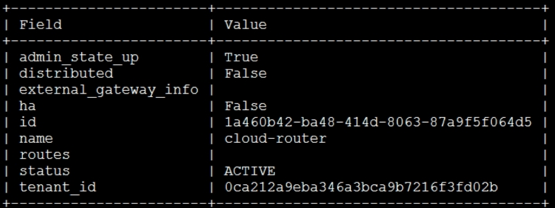
You will get a confirmation that the interface has been added and its gateway has been set.
Since the images they need are already in the Glance repository, we are now ready to hand over the cloud to the development team for them to use. If more images need to be added in the repository for different operating systems, please follow the same steps as mentioned in Chapter 3, Storing and Retrieving Data and Images using Glance, Cinder, and Swift.
Now it is time to look at the cloud from a consumer's point of view. In our example, we have Jane and John Doe, who will be the users. John is the creative artist and hence prefers the GUI, and Jane being an extremely tech savvy user, prefers the CLI or a programmatic access route. Once we as IT administrators send them emails about the cloud being ready for their consumption, they decide to quickly test whether this works for their needs.