
Chapter 14
Pipe Networks
In this chapter, we will look at pipe networks (gravity-based systems) and pressure networks. First, we will look at the setup needed to use these networks successfully. Planning is a key part of the process.
In this chapter, you will learn to:
- Create a pipe network by layout
- Create an alignment from network parts and draw parts in profile view
- Label a pipe network in plan and profile
- Create a dynamic pipe table
Parts Lists
Before you can draw pipes in your project, some setup is needed. Ideally the setup will be done in your AutoCAD® Civil 3D® template so that you don't have to repeat the process more than necessary.
A parts list contains the pieces needed to complete a pipe design. Both pipe networks and pressure networks use parts lists to help you organize design elements and determine how they will appear in a drawing. For example, you'll want different parts available when working with sanitary sewers than you'll want when working with storm sewers.
Parts lists for gravity pipe networks vary significantly from pressure pipe networks. Pipe network parts lists contain pipes, structures, pipe rules, structure rules, styles, and the ability to associate a pay item to each item.
Examples of pipe network parts lists include:
- Storm sewer
- Catch basin/inlet structures
- Manhole structures
- Concrete pipe
- HDPE pipe
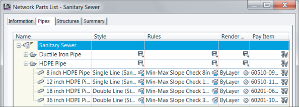
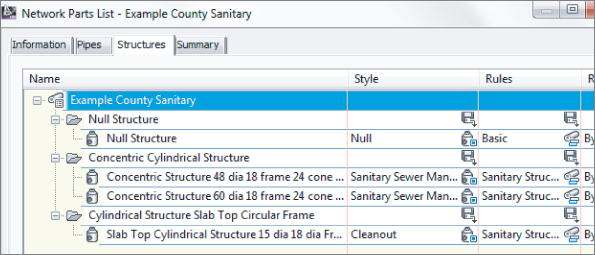
- Sanitary sewer (gravity) as shown in Figure 14.1:
- Manhole structures
- HDPE pipe
- Ductile iron pipe
Figure 14.1 Example sanitary sewer parts list
Pressure parts lists contain pipes, fittings, and appurtenances. You'll find the style for each object in the parts list, but instead of rules, pressure pipe design checks are tucked into the command settings.
Additionally, the ability to assign a pay item with the parts list is not available in this release.
Examples of pressure pipe network parts lists include:
- Water main and service connections
- Ductile iron pipe
- Tees, elbows, and crosses
- Valves
- Gas main
- PVC pipe
- Valves
In the upcoming section, you will explore planning and creating a parts list. You'll start by examining your local requirements, and then you will compare those needs with what is available in the software.
Planning a Typical Pipe Network
Let's look at a typical sanitary sewer design. You typically start by going through the sewer specifications for the jurisdiction in which you're working. There is usually a published list of allowable pipe materials, manhole details, slope parameters, and cover guidelines. Perhaps you have concrete and PVC pipe manufacturer catalogs that contain pages of details for different manholes, pipes, and junction boxes. There is usually a recommended symbology for your submitted drawings—and, of course, you have your own in-house CAD standards. Assemble this information, and make sure you address these issues:
- Recommended structures, including materials and dimensions (be sure to attach detail sheets)
- Structure behavior, such as required sump, drops across structures, and surface adjustment
- Structure symbology
- Recommended pipes, including materials and dimensions (again, be sure to attach detail sheets)
- Pipe behavior, such as cover requirements; minimum, maximum, and recommended slopes; velocity restrictions; and so on
- Pipe symbology
The following is an example of a completed checklist for our example jurisdiction, Sample County:
- Sanitary Sewers in Sample County
- Recommended Structures: Standard concentric manhole, small-diameter cleanout.
- Structure Behavior: All structures have 1.5′ (0.46 m) sump, rims, a 0.10′ (0.03 m) invert drop across all structures. All structures designed at finished road grade.
- Structure Symbology: Manholes are shown to scale in plan view as a circle with an S inside. Cleanouts are shown to scale as a hatched circle. (See Figure 14.2.)
Figure 14.2 Sanitary sewer manhole in plan view (left) and a cleanout in plan view (right)
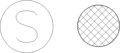
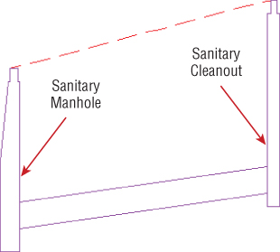
Figure 14.3 Profile view of a sanitary sewer manhole (left) and a cleanout (right)
- Recommended Pipes: 8″ (200 mm), 10″ (250 mm), and 12″ (300 mm) PVC pipe, per manufacturer specifications.
- Pipe Behavior: Pipes must have cover of 4′ (1.22 m) to the top of the pipe; the maximum slope for all pipes is 10 percent, although minimum slopes may be adjusted to optimize velocity as follows:
| Sewer size | Minimum slope |
| 8″ (200 mm) | 0.40% |
| 10″ (250 mm) | 0.28% |
| 12″ (300 mm) | 0.22% |
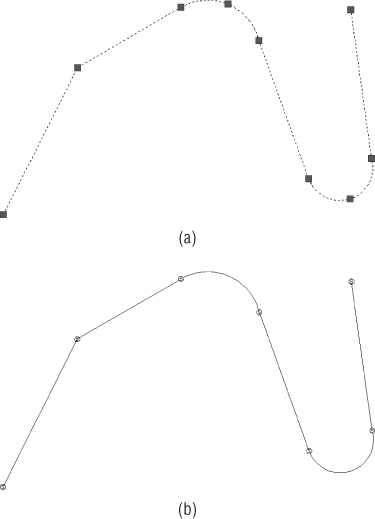
- Pipe Symbology: In plan view, pipes are shown with a CENTER2 linetype line that has a thickness corresponding to the inner diameter of the pipe. In profile view, pipes show both inner and outer walls, with a hatch between the walls to highlight the wall thickness (see Figure 14.4).
Figure 14.4 Sanitary pipe in plan view (a) and in profile view (b)

Now that you know your requirements for Sample County, the next step is to begin entering this information into your Civil 3D template file.
Part Rules
At the beginning of this chapter, you made notes about your hypothetical municipality having certain requirements for how structures and pipes behave—things like minimum slope, sump depths, and pipe-invert drops across structure. Depending on the type of network and the complexity of your design, there may be many different constraints on your design. Civil 3D allows you to establish structure and pipe rules that will assist in respecting these constraints during initial layout and edits. Some rules don't change the pipes or structures during layout but provide a “violation only” check that you can view in Prospector.
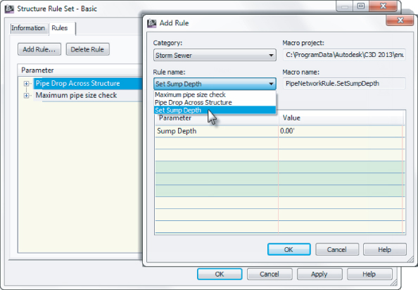
Structures and pipes have separate rule sets. When creating rules, don't be thrown off by the fact that the category always reads Storm Sewer, as you see in Figure 14.5. You can use these rules regardless of the type of parts list you are creating. You can then add these rule sets to specific parts in your parts list, which you'll build later in this chapter.
Figure 14.5 In the Add Rule dialog, the category always shows Storm Sewer but you can use rules for whatever type you wish.
Structure Rules
Structure rule sets are located on the Settings tab of Toolspace, under the Structure tree. To locate these rules in any drawing file:
You will have a chance to work with this firsthand in the upcoming exercise.
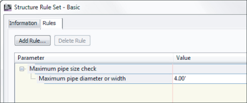
Maximum Pipe Size Check
The Maximum Pipe Size Check rule (see Figure 14.6) examines all pipes connected to a structure and flags a violation in Prospector if any pipe is larger than your rule. This is a violation-only rule—it won't change your pipe size automatically.
Figure 14.6 The Maximum Pipe Size Check rule option
Pipe Drop Across Structure
The Pipe Drop Across Structure rule (see Figure 14.7) tells any connected pipes how their inverts (or, alternatively, their crowns or centerlines) must relate to one another.
Figure 14.7 The Pipe Drop Across Structure rule options
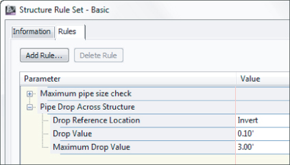
When a new pipe is connected to a structure that has the Pipe Drop Across Structure rule applied, the following checks take place:
- A pipe drawn to be exiting a structure has an invert equal to or lower than the lowest pipe entering the structure.
- A pipe drawn to be entering a structure has an invert equal to or higher than the highest pipe exiting the structure.
- Any minimum specified drop distance is respected between the lowest entering pipe and the highest exiting pipe.
In the hypothetical sanitary sewer example, you're required to maintain a 0.10′ (3 cm) invert drop across all structures. You'll use this rule in your structure rule set in the next exercise.
Set Sump Depth
Sump depth is additional structure depth below the lowest pipe invert (known in this author's area as “Mosquito Breeders”). The Set Sump Depth rule (Figure 14.8) establishes sump depth for structures.
Figure 14.8 The Set Sump Depth rule options

It's important to add a sump depth rule to all of your structure rule sets. If no sump rule is used, Civil 3D will assume a 2′ sump for English units and 2 meters in metric units! If you forget to set this before placing structures, there is no way globally to change the sump value. After the structures are placed, you would need to edit the individual structure properties or make the rule and retroactively apply it to each structure.
In the hypothetical sanitary sewer example, all the structures have a 1.5′ (0.5 m) sump depth. You'll use this rule in your structure rule set in the next exercise.
Pipe Rules
Pipe rule sets are located on the Settings tab of Toolspace, under the Pipe tree. For a detailed breakdown of pipe rules and how they're applied, including images and illustrations, please see the Civil 3D Users Guide.
After you right-click on a Pipe Rule Set and click Edit, you can access all the pipe rules by clicking the Add Rule button on the Rules tab of the Pipe Rule Set dialog.
Cover and Slope Rule
The Cover And Slope rule (Figure 14.9) allows you to specify your desired slope range and cover range. As you place your pipe network, Civil 3D tries to use the minimum and maximum depth and minimum and maximum slopes to set the initial pipe depths and slope.
Figure 14.9 The Cover And Slope rule options
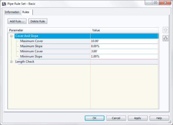
Depending on your site conditions, applying this rule to every pipe may not be feasible. In this situation, the rule becomes what is referred to as violation only. You are still able to place pipes, and the rule will cause a violation message to show in the Pipe Network panel.
If part of your design changes and you'd like Civil 3D to make another attempt to enforce the cover and slope rule, you can use the Apply Rules feature.
You'll create one Cover And Slope rule for each size pipe in the hypothetical sanitary sewer example.
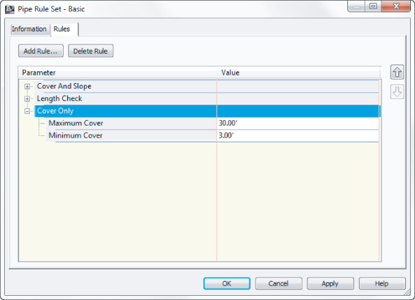
Cover Only Rule
The Cover Only rule (Figure 14.10) is designed for use with pipe systems where slope can vary or isn't a critical factor. Like Cover And Slope, this rule is used on first placement. Manual edits can cause rules to be violated. The rule will show as a violation in the Pipe Network panel, but not changes to your design take place until you use the Apply rules command.
Figure 14.10 The Cover Only rule options
Length Check
Length Check is a violation-only rule; it won't change your pipe length size automatically. The Length Check options (see Figure 14.11) allow you to specify a minimum and maximum pipe length.
Figure 14.11 The Length Check rule options

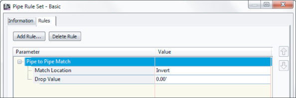
Pipe To Pipe Match Rule
The Pipe To Pipe Match rule (Figure 14.12) is also designed for use where there are no true structures (only null structures), including situations where pipe is placed to break into an existing pipe. This rule determines how pipe inverts are assigned when two pipes come together, similar to the Pipe Drop Across Structure rule.
Figure 14.12 The Pipe To Pipe Match rule options
Set Pipe End Location Rule
Without the Set Pipe End Location rule (Figure 14.13), Civil 3D assumes you are measuring pipes from center of structure to center of structure. With the rule in place, you have the capability to set where the pipe end is located on the structure. The options are Structure Center (the default without the rule), Structure Inner Wall, or Structure Outer Wall.
Figure 14.13 The Set Pipe End Location rule options

End Offset and Start Offset are used if you would like to have your pipes protrude past the inner or outer wall on the respective ends. The offset is ignored if the location for the end is set to the center of the structure. The value must be positive and will be ignored if the additional length causes the pipe end to be located past the center of the structure.
Creating Structure and Pipe Rule Sets
In this exercise, you'll create one structure rule set and three pipe rule sets for a hypothetical sanitary sewer project:
| Drop Reference Location | Invert |
| Drop Value | 0.1′ (0.03 m) |
| Maximum Drop Value | 3′ (1 m) |
| Maximum Cover | 10′ (3m) |
| Maximum Slope | 10% |
| Minimum Cover | 4′ (1.5m) |
| Minimum Slope | 0.40% |
| Maximum Cover | 10′ (3 m) |
| Maximum Slope | 10% |
| Minimum Cover | 4′ (1.5 m) |
| Minimum Slope | 0.28% |
| Maximum Cover | 10′ (3 m) |
| Maximum Slope | 10% |
| Minimum Cover | 4′ (1.5 m) |
| Minimum Slope | 0.22% |
Putting Your Parts List Together
The next step is to put your efforts from earlier in the chapter in a consolidated place. Everything you've done in this chapter up to this point is leading up to the creation of the parts list.
Your parts lists should reside in your Civil 3D template file. There is quite a bit of setup involved, and having this information in your template will ensure you need to do it only once. You will have multiple parts lists for each type of system you are creating and possibly for each jurisdiction you work in.
You should complete the previous exercise before continuing, as we will reference the rules you created there.
Figure 14.14 Add a part family for your new parts list.
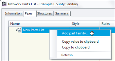
Figure 14.15 Add a new part size to the part family PVC Pipe.
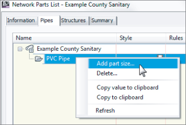
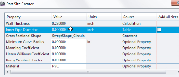
Figure 14.16 Set diameter and material for all the needed pipes.
![]()
Figure 14.17 The completed Pipes tab

![]()
Figure 14.18 Completed Structures tab in your new parts list
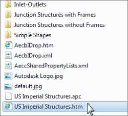
C:ProgramDataAutodeskC3D 2013enuPipes Catalog
Exploring Pipe Networks
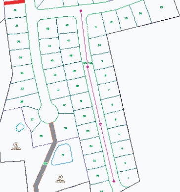
Parts in a pipe network have relationships that follow a network paradigm. A pipe network, such as the one in Figure 14.19, can have many branches. In most cases, the pipes and structures in your network will be connected to each other; however, they don't necessarily have to be physically touching to be included in the same pipe network.
Figure 14.19 A typical Civil 3D pipe network
Land Desktop with Civil Design and some other civil engineering design programs don't design piping systems using a network paradigm; instead, they use a branch-by-branch or “run” paradigm (see Figure 14.20). Although it's possible to separate your branches into their own pipe networks in Civil 3D, your design will have the most power and flexibility if you change your thinking from a run-by-run to a network paradigm.
Figure 14.20 A pipe network with a single-pipe run
Pipe networks have the following object types:
Pipes
Pipes are components of a pipe network that primarily represent pipes, but can be used to represent any type of conduit such as culverts, gas lines, or utility cables. They can be straight or curved, and although primarily used to represent gravity systems, they can be adapted and customized to represent pressure and other types of systems such as water networks and force mains.
Structures
Structures are the components of a pipe network that represent manholes, catch basins, inlets, joints, and any other type of junction between two pipes. The standard catalog includes inlets, outlets, junction structures with frames (such as manholes with lids or catch basins with grates), and junction structures without frames (such as simple cylinders and rectangles). Again, you can use Part Builder to create your own shapes and materials if needed.
Null Structures
Null structures are needed when two pipes are joined together without a structure; they act as a placeholder for a pipe endpoint. They have special properties, such as allowing pipe cleanup at pipe intersections. Most of the time, you'll create a style for them that doesn't plot or is invisible for plotting purposes.
Creating a Sanitary Sewer Network
Earlier, you prepared a parts list for a typical sanitary sewer network. This chapter will lead you through several methods for using that parts list to design, edit, and annotate a pipe network.
There are several ways to create pipe networks. You can do so using the Civil 3D pipe layout tools. You can also create pipe networks from certain AutoCAD and Civil 3D objects, such as lines, polylines, alignments, and feature lines.
Creating a Pipe Network with Layout Tools
Creating a pipe network with layout tools is much like creating other Civil 3D objects. After naming and establishing the parameters for your pipe network, you're presented with a special toolbar that you can use to lay out pipes and structures in plan, which will also drive a vertical design.
Establishing Pipe Network Parameters
This section will give you an overview of establishing pipe network parameters. Use this section as a reference for the exercises in this chapter. When you're ready to create a pipe network, select the Home tab ⇒ Create Design panel and choose Pipe Network ⇒ Pipe Network Creation Tools. The Create Pipe Network dialog appears (see Figure 14.21), and you can establish your settings.
Figure 14.21 The Create Pipe Network dialog
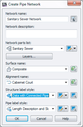
Before you can create a pipe network, you must give your network a name, but more important, you need to assign a parts list for your network. As you saw earlier, the parts list provides a toolkit of pipes, structures, rules, and styles to automate the pipe network design process. It's also important to select a reference surface in this interface. This surface will be used for rim elevations and rule application.
When creating a pipe network, you're prompted for the following options:
Network Name
Choose a name for your network that is meaningful and will help you identify it in Prospector and other locations.
Network Description
The description of your pipe network is optional. You might make a note of the date, the type of network, and any special characteristics.
Network Parts List
Choose the parts list that contains the parts, rules, and styles you want to use for this design.
Surface Name
Choose the surface that will provide a basis for applying cover rules as well as provide an insertion elevation for your structures (in other words, rim elevations). You can change this surface later or for individual structures. For proposed pipe networks, this surface is usually a finished ground surface.
Alignment Name
Choose an alignment that will provide station and offset information for your structures in Prospector as well as any labels that call for alignment stations and/or offset information. Because most pipe networks have several branches, it may not be meaningful for every structure in your network to reference the same alignment. Therefore, you may find it better to leave your Alignment option set to None in this dialog and set it for individual structures later using the layout tools or structure list in Prospector.
Using the Network Layout Creation Tools
![]()
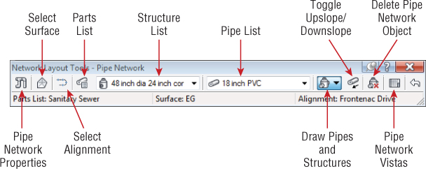
After establishing your pipe network parameters in the Create Pipe Network dialog (shown earlier in Figure 14.21), click OK; the Network Layout Tools toolbar appears (see Figure 14.22).
Figure 14.22 The Network Layout Tools toolbar
![]()
Clicking the Pipe Network Properties tool displays the Pipe Network Properties dialog, which contains the settings for the entire network. If you mistyped any of the parameters in the original Create Pipe Network dialog, you can change them here. In addition, you can set the default label styles for the pipes and structures in this pipe network.
The Pipe Network Properties dialog contains the following tabs:
Information
On this tab, you can rename your network, provide a description, and choose whether you'd like to see network-specific tooltips.
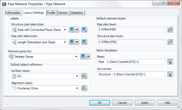
Layout Settings
Here you can change the default label styles, parts list, reference surface and alignment, master object layers for plan pipes and structures, as well as name templates for your pipes and structures (see Figure 14.23).
Figure 14.23 The Layout Settings tab of the Pipe Network Properties dialog
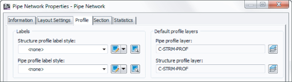
Profile
On this tab, you can change the default label styles and master object layers for profile pipes and structures (see Figure 14.24).
Figure 14.24 The Profile tab of the Pipe Network Properties dialog
Section
Here you can change the master object layers for network parts in a section (see Figure 14.25).
Figure 14.25 The Section tab of the Pipe Network Properties dialog

Statistics
This tab gives you a snapshot of your pipe network information, such minimum and maximum as elevation information, pipe and structure quantities, and references in use such as alignments and surfaces (see Figure 14.26).
Figure 14.26 The Statistics tab of the Pipe Network Properties dialog

![]()
The Select Surface tool on the Network Layout Tools toolbar allows you to switch between reference surfaces while you're placing network parts. For example, if you're about to place a structure that needs to reference the existing ground surface but your network surface was set to a proposed ground surface, you can click this tool to switch to the existing ground surface.
![]()
The Select Alignment tool on the Network Layout Tools toolbar lets you switch between reference alignments while you're placing network parts, similar to the Select Surface tool.
![]()
The Parts List tool allows you to switch parts lists for the pipe network.
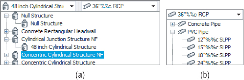
The Structure drop-down list (the image on the left in Figure 14.27) lets you choose which structure you'd like to place next, and the Pipes drop-down list (the image on the right in Figure 14.27) allows you to choose which pipe you'd like to place next. Your choices come from the network parts list.
Figure 14.27 (a) The Structure drop-down list, and (b) the Pipes drop-down list
The options for the Draw Pipes and Structures category let you choose what type of parts you'd like to lay out next. You can choose Pipes And Structures, Pipes Only, or Structures Only.
Placing Parts in a Network
You place parts much as you do other Civil 3D objects or AutoCAD objects such as polylines. You can use your mouse, transparent commands, dynamic input, object snaps, and other drawing methods when laying out your pipe network.
If you choose Pipes And Structures, a structure is placed wherever you click, and the structures are joined by pipes. If you choose Structures Only, a structure is placed wherever you click, but the structures aren't joined. If you choose Pipes Only, you can connect previously placed structures. If you have Pipes Only selected and there is no structure where you click, a null structure is placed to connect your pipes.
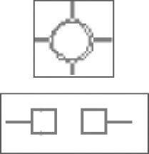
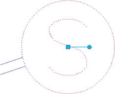
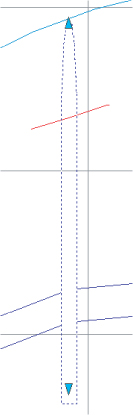
While you're actively placing pipes and structures, you may want to connect to a previously placed part. For example, there may be a service or branch that connects into a structure along the main trunk. Begin placing the new branch. When you're ready to tie into a structure, you get a circular connection marker (shown at the top of Figure 14.28) as your cursor comes within connecting distance of that structure. If you click to place your pipe when this marker is visible, a structure-to-pipe connection is formed. If you're placing parts and you'd like to connect to a pipe, hover over the pipe you'd like to connect to until you see a connection marker that has two square shapes.
Figure 14.28 The Structure Connection marker and the Pipe Connection marker
Clicking to connect to the pipe breaks the pipe in two pieces and places a structure (or null structure) at the break point.
![]()
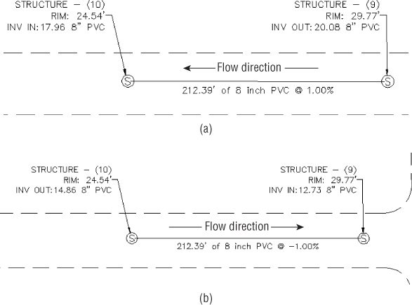
The Toggle Upslope/Downslope tool changes the flow direction of your pipes as they're placed. In Figure 14.29, Structure 9 was placed before Structure 10.
Figure 14.29 Using (a) the Downslope toggle and (b) the Upslope toggle to create a pipe network leg


![]()
Click Delete Pipe Network Object to delete pipes or structures of your choice. AutoCAD Erase can also delete network objects, but using it requires you to leave the Network Layout Tools toolbar.
![]()
Clicking Pipe Network Vistas brings up Panorama (see Figure 14.30), where you can make tabular edits to your pipe network while the Network Layout Tools toolbar is active.
Figure 14.30 Pipe Network Vistas via Panorama

The Pipe Network Vistas interface is similar to what you encounter in the Pipe Networks branch of Prospector. The advantage of using Pipe Network Vistas is that you can make tabular edits without leaving the Network Layout Tools toolbar. You can edit pipe properties, such as Invert and Slope, on the Pipes tab, and you can edit structure properties, such as Rim and Sump, on the Structure tab.
Creating a Sanitary Sewer Network
This exercise will apply the concepts taught in this section, and give you hands-on experience using the Network Layout Tools toolbar:
![]()
- Network Name: Sanitary Sewer Network
- Network Parts List: Sanitary Sewer
- Surface Name: Composite
- Alignment Name: Cabernet Court
- Structure Label Style: Data with Connected Pipes (Sanitary)
- Pipe Label Style: Length Description and Slope
![]()
Figure 14.31 The connection marker appears when your cursor is near the existing structure.

Creating a Storm Drainage Pipe Network from a Feature Line
![]()
If you already have an object in your drawing that represents a pipe network (such as a polyline, an alignment, or a feature line), you may be able to take advantage of the Create Pipe Network From Object command in the Pipe Network drop-down menu.
This option can be used for applications such as converting surveyed pipe runs into pipe networks and bringing forward legacy drawings that used AutoCAD linework to represent pipes. Because of some limitations described later in this section, it isn't a good idea to use this in lieu of Create Pipe Network By Layout for new designs.
It's often tempting in Civil 3D to rely on your former drawing habits and try to “convert” your AutoCAD objects into Civil 3D objects. You'll find that the effort you spend learning Create Pipe Network By Layout pays off quickly with a better-quality model and easier revisions.
The Create Pipe Network From Object option creates a pipe for every linear segment of your object and places a structure at every vertex of your object. For example, the polyline with three line segments and three arcs, shown in Figure 14.32, is converted into a pipe network containing three straight pipes, three curved pipes, and seven structures—one at the start, one at the end, and one at each vertex.
Figure 14.32 (a) A polyline showing vertices and (b) a pipe network created from the polyline
This option is most useful for creating pipe networks from long, single runs. It can't build branching networks or append objects to a pipe network. For example, if you create a pipe network from one feature line and then, a few days later, receive a second feature line to add to that pipe network, you'll have to use the pipe-network editing tools to trace your second feature line; no tool lets you add AutoCAD objects to an already-created pipe network. However, once a pipe network exists, you can merge it into another using the Merge Networks command.
This exercise will give you hands-on experience building a pipe network from a feature line with elevations:
![]()
Figure 14.33 Flow-direction preview
- Network Name: Storm Network
- Network Parts List: Storm Sewer
- Pipe To Create: 12 Inch Concrete Pipe (300 mm Concrete Pipe)
- Structure To Create: From the Rectangular Junction Structure NF collection 2 × 2 Rectangular Structure (750 × 750 mm Rectangular Structure)
- Surface Name: Composite
- Alignment Name: <none>
- Erase Existing Entity check box: Selected
- Use Vertex Elevations check box: Selected
- Set Vertex Elevation Reference to Invert
This has combined all your object-created networks into a more manageable single network.
Changing Flow Direction
To change flow direction, select any part from a pipe network to open the Pipe Networks Contextual tab. Select Change Flow Direction from the Modify panel. Change Flow Direction allows you to reverse the pipe's understanding of which direction it flows, which comes into play when you're using the Apply Rules command and when you're annotating flow direction with a pipe label-slope arrow.
Changing the flow direction of a pipe doesn't make any changes to the pipe's invert. By default, a pipe's flow direction depends on how the pipe was drawn and how the Toggle Upslope/Downslope tool was set when the pipe was drawn:
- If the toggle was set to Downslope, the pipe flow direction is set to Start To End, which means the first endpoint you placed is considered the start of flow and the second endpoint is established as the end of flow.
- If the toggle was set to Upslope when the pipe was drawn, the pipe flow direction is set to End To Start, which means the first endpoint placed is considered the end for flow purposes and the second endpoint the start.
After pipes are drawn, you can set four additional flow options—Start To End, End To Start, Bi-directional, and By Slope—in Pipe Properties:
Start To End
A pipe label-flow arrow shows the pipe direction from the first pipe endpoint drawn to the second endpoint drawn, regardless of invert or slope.
End To Start
A pipe label-flow arrow shows the pipe direction from the second pipe endpoint drawn to the first pipe endpoint drawn, regardless of invert or slope.
Bi-directional
Typically, this is a pipe with zero slope that is used to connect two bodies that can drain into each other, such as two stormwater basins, septic tanks, or overflow vessels. The direction arrow is irrelevant in this case.
By Slope
A pipe label-flow arrow shows the pipe direction as a function of pipe slope. For example, if End A has a higher invert than End B, the pipe flows from A to B. If B is edited to have a higher invert than A, the flow direction flips to be from B to A.
Editing a Pipe Network
You can edit pipe networks in several ways:
- Using drawing layout edits such as grip, move, and rotate
- Grip-editing the pipe size
- Using vertical movement edits using grips in profile (see the “Vertical Movement Edits Using Grips in Profile” section later in this chapter)
![]()
Using tabular edits in the Pipe Networks branch in Prospector, or from Panorama in the pipe toolbar
- Right-clicking a network part to access tools such as Swap Part or Pipe/Structure Properties
- Returning to the Network Layout Tools toolbar by right-clicking the object and choosing Edit Network
- Selecting the pipe network in Toolspace-Prospector, right-clicking, and choosing Edit Network
- Selecting a network part to access the Pipe Networks contextual tab on the Ribbon
You will have the chance to explore most of these methods in the following sections.
Editing Your Network in Plan View
When selected, a structure has two types of grips, shown in Figure 14.34. The first is a square grip located at the structure insertion point. You can use this grip to grab the structure and stretch/move it to a new location using the insertion point as a base point. Stretching a structure results in the movement of the structure as well as any connected pipes. You can also scroll through Stretch, Move, and Rotate by using your spacebar once you've grabbed the structure by this grip.
Figure 14.34 Two types of structure grips
The second structure grip is a rotational grip that you can use to spin the structure about its insertion point. This is most useful for aligning eccentric structures, such as rectangular junction structures.
In plan view, many common AutoCAD Modify commands work with structures. You can execute the following commands normally: Move, Copy, Rotate, Align, and Mirror. (Scale doesn't have an effect on structures.) Keep in mind that the Modify commands are applied to the structure model itself; depending on how you have your style established, it may not be clear that you've made a change.
You can use the AutoCAD Erase command to erase network parts. Note that erasing a network part in plan completely removes that part from the network. Once erased, the part disappears from plan, profile view, Prospector, and so on.
When selected, a pipe end has two types of grips (see Figure 14.35). The first is a square endpoint-location grip. Using this grip, you can change the location of the pipe end without constraint. You can move it in any direction; make it longer or shorter; and take advantage of Stretch, Move, Rotate, and Scale by using your spacebar.
Figure 14.35 Two types of pipe-end grips
The second grip is a pipe-length grip. This grip lets you extend a pipe along its current bearing.
A pipe midpoint also has two types of grips (see Figure 14.36). The first is a square location grip that lets you move the pipe using its midpoint as a base point. As before, you can take advantage of Stretch, Move, Rotate, and Scale by using your spacebar.
Figure 14.36 Two types of pipe midpoint grips

The second grip is a triangular-shaped pipe-diameter grip. Stretching this grip gives you a tooltip showing allowable diameters for that pipe, which are based on your parts list. Use this grip to make quick, visual changes to the pipe diameter.
Structure Rotation
While dynamic input is active, you get a tooltip that tracks rotation angle.

Pipe Diameter
When you're using the pipe-diameter grip edit, dynamic input gives you a tooltip to assist you in choosing your desired diameter. Note that the tooltip depends on your drawing units.

Pipe Length
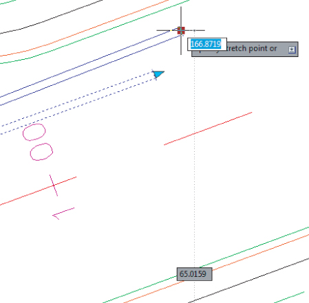
This is probably the most common reason to use dynamic input for pipe edits. Choosing the pipe-length grip when dynamic input is active shows tooltips for the pipe's current length and preview length, as well as fields for entering the desired pipe total length and pipe delta length. Use your Tab key to toggle between the Total Length and Delta Length fields. One of the benefits of using dynamic input in this interface is that even though you can't visually grip-edit a pipe to be shorter than its original length, you can enter a total length that is shorter than the original length. Note that the length shown and edited in the dynamic input interface is the 3D center-to-center length.

Pipe Endpoint Edits
Similar to pipe length, pipe endpoint location edits can benefit from using dynamic input. The active fields give you an opportunity to input x- and y-coordinates.
Pipe Vertical Grip Edits in Profile
Using dynamic input in profile view lets you set exact invert, centerline, or top elevations without having to enter the Pipe Properties dialog or Prospector. Choose the appropriate grip, and note that the active field is Tracking Profile Elevation. You may need to zoom out to see the elevation field. Enter your desired elevation, and your pipe will move as you specify.

Making Tabular Edits to Your Pipe Network
Another method for editing pipe networks is in a tabular form using the Pipe Networks branch in Prospector (see Figure 14.37).
Figure 14.37 The Pipe Networks branch in Prospector

To edit pipes in Prospector, highlight the Pipes entry under the appropriate pipe network. For example, if you want to edit your sanitary sewer pipes, expand the Sanitary Sewers branch and select the Pipes entry. You should get a preview pane that lists the names of your pipes and some additional information in a tabular form. The same procedure can be used to list the structures in the network.
White columns can be edited in this interface. Gray columns are considered calculated values and therefore can't be edited.
You can adjust many things in this interface, but you'll find it cumbersome for some tasks. The interface is best used for the following:
Batch Changes to Styles, Render Materials, Reference Surfaces, Reference Alignments, Rule Sets, and So On
Use your Shift or Ctrl key to select the desired rows, and then right-click the column header of the property you'd like to change. Choose Edit, and then select the new value from the drop-down menu. If you find yourself doing this on every project for most network parts, confirm that you have the correct values set in your parts list and in the Pipe Network Properties dialog.
Batch Changes to Pipe Description
Use your Shift key to select the desired rows, and then right-click the Description column header. Choose Edit, and then type in your new description. If you find yourself doing this on every project for most network parts, check your parts list. If a certain part will always have the same description, you can add it to your parts list and prevent the extra step of changing it here.
Changing Pipe or Structure Names
You can change the name of a network part by typing in the Name field. If you find yourself doing this on every project for every part, check that you're taking advantage of the Name templates in your Pipe Network Properties dialog (which can be further enforced in your Pipe Network command settings).
You can Shift-click and copy the table to your Clipboard and insert it into Microsoft Excel for sorting and further study. (This is a static capture of information; your Excel sheet won't update along with changes to the pipe network.)
This interface can be useful for changing pipe inverts, crowns, and centerline information. It's not always useful for changing the part rotation, insertion point, start point, or endpoint. It isn't as useful as many people expect because the pipe inverts don't react to each other. If Pipe A and Pipe B are connected to the same structure, and Pipe A flows into Pipe B, changing the end invert of Pipe A does not affect the start invert of Pipe B automatically. If you're used to creating pipe design spreadsheets in Excel using formulas that automatically drop connected pipes to ensure flow, this behavior can be frustrating.
Pipe Network Contextual Tab Edits
You can perform many edits at the individual part level by selecting it. The Pipe Network contextual tab will appear for the object you are working with.
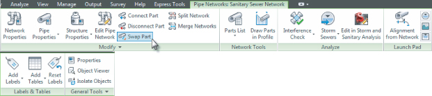
If you realize you placed the wrong part at a certain location—for example, if you placed a catch basin where you need a drainage manhole—use the Swap Part option on the contextual tab (see Figure 14.38). You're given a list of all the parts from all the parts lists in your drawing.
Figure 14.38 Selecting a network part brings up a contextual tab with many options, including Swap Part.
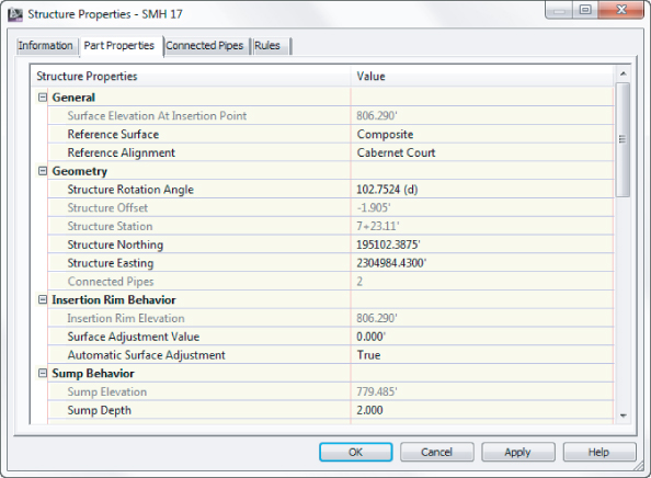
The same properties listed in Prospector (or Pipe Network Vista) can be accessed on an individual part level by clicking and choosing Pipe Properties or Structure Properties from the contextual tab. A dialog like the Structure Properties dialog in Figure 14.39 opens, with several tabs that you can use to edit that particular part.
Figure 14.39 The Part Properties tab in the Structure Properties dialog gives you the opportunity to perform many edits and adjustments.
The Labels & Tables Panel
The Labels & Tables panel is where you do the most annotation labeling for pipes. You can access Labels & Table from the Annotate tab, or if you click on a pipe network, you will find it on the contextual menu.
![]()
Add Labels
For the best control over what styles are used in your label, use the Add Pipe Network Labels option. From there, you can add labels for the selected pipe network using the suboptions such as Entire Network Plan, Entire Network Profile, Entire Network Section, Single Part Plan, Single Part Profile, Single Part Section, Spanning Pipes Plan, and Spanning Pipes Profile.
![]()
Add Tables
You can add a structure or pipe table.
![]()
Reset Labels
This Reset Labels is different from the Reset Label option you see when clicking directly on a label. In this version of the command, pipe networks that are in the drawing via data reference will be labeled using styles from the source drawing. For more information on source drawings and data references, see Chapter 18, “Advanced Workflows.”
The General Tools Panel
While not specifically for pipe networks or even Civil 3D for that matter, these tools are placed here for convenience.
![]()
Properties
Toggles the Properties palette on and off.
![]()
Object Viewer
Allows you to view the selected object or objects in 3D via a separate viewer.
![]()
Isolate Objects
Selected objects will be the only objects visible on the screen. This is useful if you are working in a tight area and do not wish to see extraneous objects, and it is much quicker than clicking to turn off or freeze layers.
![]()
Select Similar
When this tool is invoked, it will select all similar type objects.
![]()
Quick Select or QSelect
Opens the Quick Select dialog, which allows custom filtering.
![]()
![]()
Draw Order Icons
Allow you to move objects either to the front or back of other objects, or above or behind a specific object.
The Modify Panel
The Modify Panel is where you do editing of an existing pipe network. It can also be selected by clicking on a pipe network and selecting it from the right-click contextual menu.
![]()
Network Properties Tool
Opens the Pipe Network Properties dialog.
![]()
Pipe Properties Tool
Opens the Pipe Properties dialog. If you are seeing the Modify panel because you have selected a structure, you will be prompted to select a pipe.
![]()
Edit Pipe Style Tool
Opens the Pipe Style dialog. If you are seeing the Modify panel because you have selected a structure, you will be prompted to select a pipe. For more on pipe styles, see Chapter 19.
![]()
Structure Properties Tool
Opens the Structure Properties dialog. If you are seeing the Modify panel because you have selected a pipe, you will be prompted to select a structure.
![]()
Edit Structure Style Tool
Opens the Structure Style dialog. For more on structure styles, see Chapter 19.
![]()
Edit Pipe Network Tool
Opens the Network Layout Tools toolbar.
![]()
Connect And Disconnect Part Tools
Allow you to connect pipes to structures that may have been disconnected and to disconnect pipes from structures.
![]()
Swap Part Tool
Allows you to replace a structure or pipe type with another one from a Swap Part Size dialog.
![]()
Split and Merge Network Tools
Allow you to take an existing network and split it into two networks, or take an existing pipe network and merge it into another pipe network.
![]()
Rename Parts Tool
Opens the Rename Pipe Network Parts dialog. Here, you can rename pipes and structures, modify pipe numbering, and decide how you want to handle conflicting names or numbers.
![]()
Apply Rules Tool
Forces the set rule on the selected objects.
![]()
Change Flow Direction Tool
Changes the path of the selected objects. It is very important to have this option set correctly if you are going to use any of the analysis programs.
The Network Tools Panel
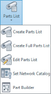
The Parts List drop-down on the Network Tools panel contains the following tools:
Create Parts List
Allows you to create new parts list via the Network Parts List – New Parts List dialog.
Create Full Parts List
Takes all the parts available in the parts catalog and creates a list called Full Catalog.
Edit Parts List
Opens the Parts List dialog, where you can select the network to add to an existing or new pipe network.
Set Network Catalog
Opens the Pipe Network Settings dialog, where you can select whether you wish to use Imperial or metric parts, and also sets the location of the Network Catalog.
Part Builder
Opens the Part Builder tool.
![]()
Draw Parts In Profile View
Adds the selected pipe network objects into an existing profile.
The Analyze Panel
The Analyze Panel contains the following tools for doing various checks on a pipe network.
![]()
Interference Check Properties
Allows you to create an interference check between parts, whether or not they are on the same network. The following tools are available via the submenu:
![]()
Create Interference Check Tool
This is the same as the Interference Check Properties tool.
![]()
When you select the Interference Check Properties tool, you are prompted to select Interference and then the Interference Check Properties dialog opens:
- The Information tab displays basic information such as the name of the interference set, style, rendering material, and layer.
- The Criteria tab contains specific editable items, such as whether to use 3D proximity check, distance, and scale factors.
- The Statistics tab is a combined listing of the other tabs but also allows you to see the networks used for the interference check.
![]()
Interference Properties Tool
Interference Properties will give you information about a single interference location in your drawing. This differs from the Interference Check Properties in that you can't change the criteria from here. You only see the following information about a specific instance of interference:
- Information tab (where you can name the individual interference objects)
- Statistics tab (which contains the X-Y location of the selected interference object)
![]()
Edit Interference Style Tool
Opens the Interference Style dialog, where you can change the visual parameters for the interference object. For more on styles, see Chapter 19.
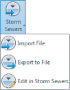
Storm Sewers Tool
These commands interact with the Hydraflow Storm Sewers Extension. Hydraflow is a separate program that is included with Civil 3D. An in-depth discussion of Hydraflow is beyond the scope of this book; see the Hydraflow Storm Sewers Extension help files for more information.
![]()
Edit In Storm And Sanitary Analysis Tool
Opens the Storm and Sanitary Analysis (SSA) program. For more on SSA, see Chapter 15, “Storm and Sanitary Analysis.”
The Launch Pad Panel
![]()
The Launch Pad panel contains the following tools:
Alignment From Network
Allows you to create an alignment from pipe network parts.
![]()
Storm Sewers Tool
Opens the Hydroflow Storm Sewers program.
![]()
Hydrographs Tool
Opens the Hydraflow Hydrographs program. Hydraflow Hydrographs is a separate program that is included with Civil 3D. An in-depth discussion of Hydraflow Hydrographs is beyond the scope of this book; see the Hydraflow Hydrographs Extension help files for more information.
![]()
Express Tool
Opens the Hydraflow Express program. Hydraflow Express is a separate program that is included with Civil 3D. An in-depth discussion of Hydraflow Express is beyond the scope of this book; see the Hydraflow Express help files for more information.
Editing with the Network Layout Tools Toolbar
You can also edit your pipe network by retrieving the Network Layout Tools toolbar. This is accomplished by selecting a pipe network object and choosing Edit Network from the context tab. You can also go to the Modify tab and click Pipe Network on the Design panel.
Once the toolbar is up, you can continue working exactly the way you did when you originally laid out your pipe network.
This exercise will give you hands-on experience in making a variety of edits to a sanitary and storm-drainage pipe network:
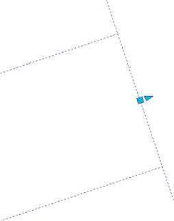
Figure 14.40 Rotate and move the catch basin into place along the curb.
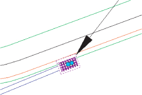
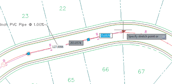
Figure 14.41 Lengthen the pipe to 200′ (60.96 m).
![]()
![]()
Creating an Alignment from Network Parts
On some occasions, certain legs of a pipe network require their own stationing. Perhaps most of your pipes are shown on a road profile but the legs that run offsite or through open space require their own profiles. Whatever the reason, it's often necessary to create an alignment from network parts. Follow these steps:
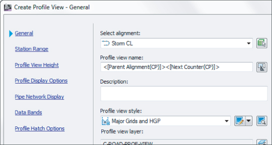
- Name your alignment Storm CL.
- Notice the Create Profile And Profile View check box on the last line of the dialog. Leave the box selected and click OK.
Figure 14.42 The Create Profile From Surface dialog

Figure 14.43 The Create Profile View Wizard
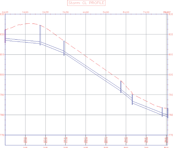
You see three structures and two pipes drawn in a profile view, which is based on the newly created alignment (see Figure 14.44).
Figure 14.44 Creating a profile view
Drawing Parts in Profile View
![]()
To add pipe network parts to an existing profile view, select a network part, and choose Draw Parts In Profile from the Network Tools panel on the contextual tab. When you're using this command, it's important to note that only selected parts are drawn in your chosen profile view.
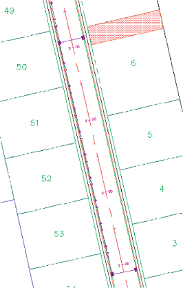
Profiles and profile views are always cut with respect to an alignment. Therefore, pipes are shown in the profile view on the basis of how they appear along that alignment, or how they cross that alignment. Unless your alignment exactly follows the centerline of your network parts, your pipes will likely show some drafting distortion.
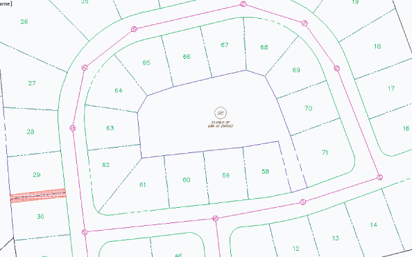
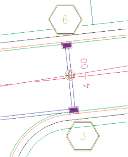
Let's look at Figure 14.45 as an example. This particular jurisdiction requires that all utilities be profiled along the road centerline. There's a road centerline, a storm network that jogs across the road to connect with another catch basin.
Figure 14.45 These pipe lengths will be distorted in profile view.
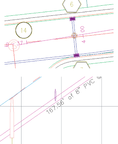
At least two potentially confusing elements show up in your profile view. First, the distance between structures (2D Length - Center To Center) isn't the same between the plan and the profile (see Figure 14.46) because the storm pipe doesn't run parallel to the alignment. Because the labeling reflects the network model, all labeling is true to the 2D Length - Center To Center or any other length you specify in your label style.
Figure 14.46 Pipe labels in plan view (top) and profile view (bottom)
The second potential issue is that the invert of your crossing storm pipe is shown at the point where the storm pipe crosses the alignment, and not at the point where it crosses the sanitary pipe (see Figure 14.47).
Figure 14.47 The invert of a crossing pipe is drawn at the location where it crosses the alignment.

Vertical Movement Edits Using Grips in Profile
Although you can't make changes to certain part properties (such as pipe length) in profile view, pipes and structures both have special grips for changing their vertical properties in profile view.
When selected, a structure has two grips in profile view (see Figure 14.48). The first is a triangular-shaped grip representing a rim insertion point. This grip can be dragged up or down and affects the model structure-insertion point.
Figure 14.48 A structure has two grips in profile view.
Moving this grip can affect your structure insertion point two ways, depending on how your structure properties were established:
- If your structure has Automatic Surface Adjustment set to True, grip-editing this Rim Insertion Point grip changes the surface adjustment value. If your reference surface changes, then your rim will change along with it, plus or minus the surface adjustment value.
- If your structure has the Automatic Surface Adjustment set to False, grip-editing this Rim grip modifies the insertion point of the rim. No matter what happens to your reference surface, the rim will stay locked in place.
Typically, you'll use the Rim Insertion Point grip only in cases where you don't have a surface for your rims to target to, or if you know there is a desired surface adjustment value. It's tempting to make a quick change instead of making the improvements to your surface that are fundamentally necessary to get the desired rim elevation. One quick change often grows in scope. Making the necessary design changes to your target surface will keep your model dynamic and, in the long run, will make editing your rim elevations easier.
The second grip is a triangular grip located at the sump depth. This grip doesn't represent structure invert. In Civil 3D, only pipes truly have invert elevation. The structure uses the connected pipe information to determine how deep it should be. When the sump has been set at a depth of 0, the sump elevation equals the invert of the deepest connected pipe.
This grip can be dragged up or down. It affects the modeled sump depth in one of two ways, depending on how your structure properties are established:
Controlling Sump By Depth
If your structure is set to control sump by depth, editing with the Sump grip changes the sump depth.
The depth is measured from the structure insertion point. For example, if the original sump depth was 0, grip-editing the sump 0.5′ (15.24 cm) lower would be the equivalent of creating a new sump rule for a 0.5′ (15.24 cm) depth and applying the rule to this structure. This sump will react to hold the established depth if your reference surface changes, your connected pipe inverts change, or something else is modified that would affect the invert of the lowest connected pipe. This triangular grip is most useful in cases where most of your pipe network will follow the sump rule applied in your parts lists, but selected structures need special treatment.
Controlling Sump By Elevation
If your structure is set to control sump by elevation, adjusting the Sump grip changes that elevation.
When sump is controlled by elevation, sump is treated as an absolute value that will hold regardless of the structure insertion point. For example, if you grip-edit your structure so its depth is 8.219′ (2.51 m), the structure will remain at that depth regardless of what happens to the inverts of your connected pipes. The Control Sump By Elevation parameter is best used for existing structures that have surveyed information of absolute sump elevations that won't change with the addition of new connected pipes.
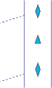
When selected, a pipe end has three grips in profile view (see Figure 14.49). You can grip-edit the invert, crown, and centerline elevations at the structure connection using these grips, resulting in the pipe slope changing to accommodate the new endpoint elevation.
Figure 14.49 Three grips for a pipe end in profile view
When selected, a pipe in profile view has one grip at its midpoint (see Figure 14.50). You can use this grip to move the pipe vertically while holding the slope of the pipe constant.
Figure 14.50 Use the Midpoint grip to move a pipe vertically.
You can access pipe or structure properties by choosing a part, right-clicking, and choosing Pipe or Structure Properties.
Removing a Part from Profile View
If you have a part in profile view that you'd like to remove from the view but not delete from the pipe network entirely, you have a few options.
AutoCAD Erase can remove a part from profile view; however, that part is then removed from every profile view in which it appears. If you have only one profile view, or if you're trying to delete the pipe from every profile view, this is a good method to use.
Be careful when using the Del key or the Erase command on objects in plan view. Keep in mind that deleting any object from plan view removes the object outright, which includes pipe network parts. Use your Esc key liberally before selecting items to remove; this will help you avoid unintended deletion of items. Of course, if you accidentally blow away something, Undo will bring it back.
A better way to remove parts from a particular profile view is through the Profile View Properties. You can access these properties by selecting the profile view, right-clicking, and choosing Profile View Properties.
The Pipe Networks tab of the Profile View Properties dialog (see Figure 14.51) provides a list of all pipes and structures that are shown in that profile view. You can deselect the check boxes next to parts you'd like to omit from this view.
Figure 14.51 Deselect parts to omit them from a view.

At the bottom of the Profile View Properties dialog is a checkbox for Show Only Parts Drawn In Profile View. This checkbox is off by default so that you can see every possible pipe and structure. When this is checked on, the Pipe Network tab will hide any pipes that are not visible in the profile view you are examining.
Showing Pipes That Cross the Profile View
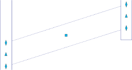
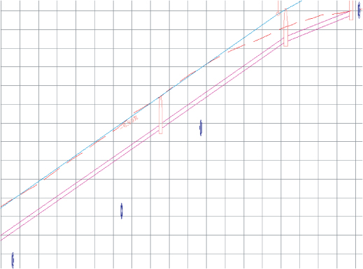
If you have pipes that cross the alignment related to your profile view, you can show them with a crossing style. A pipe must cross the parent alignment to be shown as a crossing in the profile view. The location of a crossing pipe is always shown at the elevation where it crosses the alignment (see Figure 14.52).
Figure 14.52 A pipe crossing a profile

When pipes enter directly into profiled structures, they can be shown as ellipses through the Display tab of the Structure Style dialog (see Figure 14.53). See Chapter 21, “Object Styles,” for more information about creating structure styles.
Figure 14.53 Pipes that cross directly into a structure can be shown as part of the structure style.

The first step to display a pipe crossing in profile is to add the pipe that crosses your alignment to your profile view by either selecting the pipe, right-clicking, and selecting Draw Parts In Profile from the Network Tools panel and selecting the profile view, or by checking the appropriate boxes on the Pipe Network tab of the Profile View Properties dialog. When the pipe is added, it's distorted when it's projected onto your profile view—in other words, it's shown as if you wanted to see the entire length of pipe in profile (see Figure 14.54).
Figure 14.54 The pipe crossing is distorted.
The next step is to override the pipe style in this profile view only. Changing the pipe style through pipe properties won't give you the desired result, because that will affect the visibility of every single instance of the pipe. You must override the style on the Pipe Networks tab of the Profile View Properties dialog (see Figure 14.55).
Figure 14.55 Correct the representation in the Profile View Properties dialog.
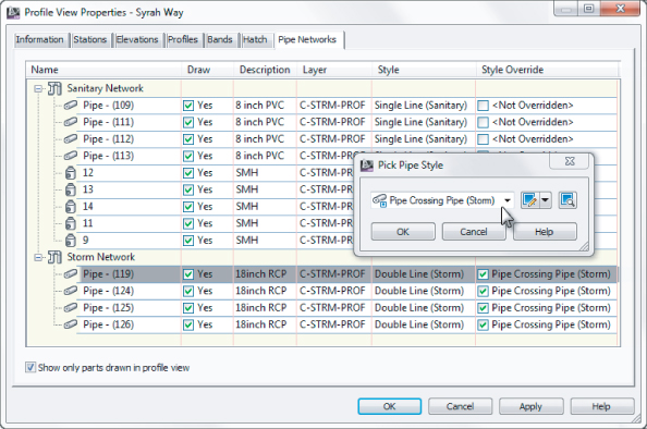
Locate the pipe you just added to your profile view, and scroll to the last column on the right (Style Override). Select the Style Override check box, and choose your pipe crossing style. Click OK. Your pipe should now appear as an ellipse.
If your pipe appears as an ellipse but suddenly seems to have disappeared in the plan and other profiles, chances are good that you didn't use the Style Override but accidentally changed the pipe style. Go back to the Profile View Properties dialog and make the necessary adjustments; your pipes will appear as you expect.
Adding Pipe Network Labels
Once you've designed your network, it's important to annotate the design. This section focuses on pipe network–specific label components in plan and profile views (see Figure 14.56).
Figure 14.56 Typical pipe network labels (top) in plan view and (bottom) in profile view

Like all Civil 3D objects, the Pipe and Structure label styles can be found in the Pipe and Structure branches of the Settings tab in Toolspace and are covered in Chapter 20, “Label Styles.”
Creating a Labeled Pipe Network Profile Including Crossings
This exercise will apply several of the concepts in this chapter to give you hands-on experience producing a pipe network profile that includes pipes that cross the alignment. You will have another chance to practice creating an alignment from a pipe network and associating the new alignment to the parts. You will also practice overriding pipe display in the Profile Properties. There are storm pipes that cross the centerline nearly perpendicular to the alignment. You will show these as ellipses in the profile view.
- Site: <none>
- Name: SMH16 to SMH18 Alignment
- Alignment Type: Miscellaneous
- Alignment Style: _None
- Alignment Label Set: _No Labels
- Create Profile And Profile View check box: Selected
Figure 14.57 The completed exercise with crossing pipes
Pipe and Structure Labels
In earlier exercises, you have already had a sneak peek at adding labels for structures. Civil 3D makes no distinction between a plan label and a profile label. The same label style can be used both places. In this chapter, we will make use of label styles that are already part of the drawing.
To create your own pipe labels from scratch, see Chapter 20.
Creating an Interference Check
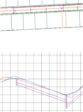
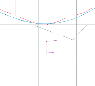
In design, you must make sure pipes and structures have appropriate separation. You can perform some visual checks by rotating your model in 3D and plotting pipes in profile and section views (see Figure 14.58). Civil 3D also provides a tool called Interference Check that makes a 3D sweep of your pipe networks and lets you know if anything is too close for comfort.
Figure 14.58 Two pipe networks may interfere vertically where crossings occur (top). Viewing your pipes in profile view can also help identify conflicts (bottom).
The following exercise will lead you through creating a pipe network and using Interference Check to scan your design for potential pipe network conflicts:
Figure 14.59 The Create Interference Check dialog

Figure 14.60 Criteria for the 3D proximity check
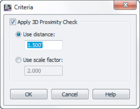
Figure 14.61 The interference marker in plan view
![]()
Figure 14.62 The interference marker in 3D

Making edits to your pipe network flags the interference check as “out of date.” You can rerun Interference Check by right-clicking Interference Check in Prospector. You can also edit your criteria in this right-click menu.
Creating Pipe Tables
Just like with parcels and labels, labeling pipes can turn into a mess with all the labels set on the plan, such as pipes and structures (see Figure 14.63). In this section, you will explore table creation for pipes and structures.
Figure 14.63 Pipes and structure labels crowded on a plan

Exploring the Table Creation Dialog
Since the structure and pipe table creation dialogs are similar, we will cover both of them in this section:
- The Table Style option allows you to select a table look or style. You can select the available styles from the arrow to the right of the table style name. You can also create new, copy, edit, or pick a table style. For more on table styles, see Chapter 20.
- The Table Layer option will set the overall layer for the table.
- With the By Network radio button selected, you can select the network to create a table from the drop-down list, or use the pick icon to select the network on the drawing.
- With the Multiple Selection radio button selected and by using the pick icon, you can select structures or pipes (depending on which table type is selected) from the drawing. You can pick pipes or structures regardless of the network.
- The Split Table check box will allow you to split the table if it gets too large. You can specify the maximum number of rows per table and the maximum number of tables per stack. Additionally, you can set the offset distance between the stacked tables.
- You can choose whether you want the split tables tiled across or down.
- The last option to choose defines the behavior you want for the table: Static or Dynamic. A static table will not update if any changes are made to the pipe network, such as swapping a part. Dynamic will update the table to those changes.
In the following exercise, you will create a pipe network table for the sanitary sewer structures:
Figure 14.64 Structure Table Creation dialog box

Figure 14.65 The finished structure table

The table creation for pipes is similar to the structure table creation process. Continue working in Pipes-Exercise3.dwg (Pipes-Exercise3_METRIC.dwg):
Figure 14.66 The Pipe Table Creation dialog
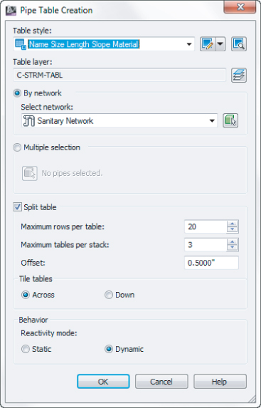
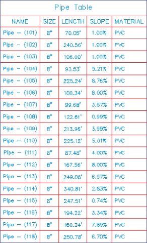
Figure 14.67 The finished pipe table
The Table Panel Tools
When you click on a table, the Table contextual tab opens and has several tools available (Figure 14.68). We'll look at each in this section.
Figure 14.68 The Table contextual tab

The General Tools Panel
The tools here are the same as mentioned earlier when we discussed the pipe network tools.
The Modify Panel
The Modify Panel contains the following tools:
![]()
Table Properties Tool
Opens the Table Properties dialog. You can set the table style and choose whether to split the table with all the options mentioned earlier. In addition, you can force realignment of stacks and force content updating.
![]()
Edit Table Style Tool
Opens the Table Style dialog. For more on editing table styles, see Chapter 20.
![]()
Static Mode Tool
Turns a dynamic table into a static table.
![]()
Update Content Tool
Forces an update on a table.
![]()
Realign Stacks Tool
Readjusts the table columns back to the default setting.
![]()
Add Items Tool
Adds pipe data to the table that was added after the table was created.
![]()
Remove Items Tool
Removes pipe or structure objects from a table.
![]()
Replace Items Tool
Allows you to swap pipe or structures in the table.
Under Pressure
New to Civil 3D 2013 are pressure networks. Pressure pipes work differently than gravity flow pipe systems within Civil 3D. Much of the need for custom parts like valves or hydrants is eliminated with these systems.
Pressure Network Parts List
Like gravity-based networks, a pressure network starts with a parts list. All of the parts available in Civil 3D are based on standards established by the American Water Works Association (AWWA), and are listed in both inches and millimeters.
Under the Hood of the Pressure Network
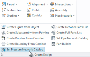
Before you can create a pressure parts list, you must decide which catalog you will be working from. Set the pressure network catalog by going to the Home tab of the ribbon ⇒ Create Design panel flyout, and select Set Pressure Network Catalog, as shown in Figure 14.69.
Figure 14.69 Setting the pressure network catalog
Set the path to the Pressure Pipes Catalog folder to C:ProgramDataAutodeskC3D 2013enuPressure Pipes Catalog. Click the folder icon to choose either the Metric or the Imperial database depending on your needs.
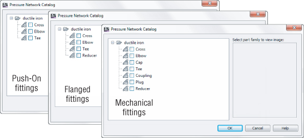
The catalog database file determines the join type between pressure network parts. The most commonly used join type in modern water main construction is the push-on type, which is the default pressure database. As shown in Figure 14.70, Imperial units have a choice of three options:
- Imperial_AWWA_Flanged
- Imperial_AWWA_Mechanical
- Imperial_AWWA_PushOn
Figure 14.70 Setting your catalog database file

Metric_AWWA_PushOn is currently the only available option for metric users.
Each of these differs slightly in their options for pipes, fittings, and appurtenances. Only one type of pressure network catalog can be active at a time. A parts list can have parts from only one catalog in it; for example, you cannot mix and match push-on with mechanical parts. You can, however, have multiple pressure parts lists in your template; each can pull parts from the various catalog database files.
Creating a Pressure Parts List
In the Settings tab of Toolspace you will find the listing for pressure networks. The Pressure Networks branch is where you will create a parts list. In the case of pressure networks, a parts list contains three components:
Pressure Pipes
Ductile iron of various sizes can be added. Like the gravity networks, each part can have a style. Furthermore, different sizes within the part families can have style, which can help you identify them in the graphic.
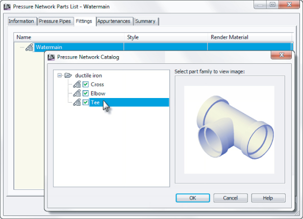
Fittings
Fittings such as T's, crosses, and elbows are specified in this tab.
Appurtenances
Valves are specified in the Appurtenances tab.
In the following exercise, you will create a pressure network parts list:
Figure 14.71 Adding ductile iron pipe to the pressure network parts list
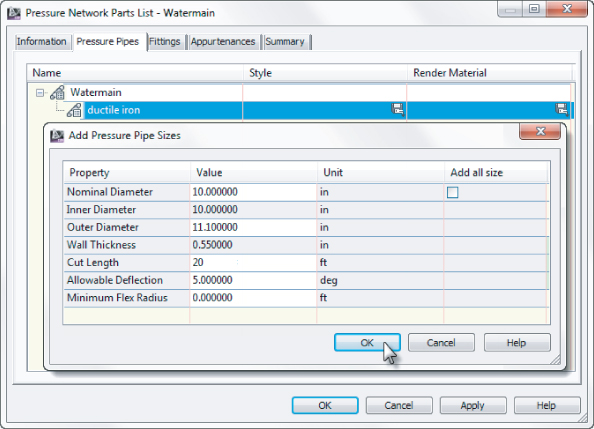
Figure 14.72 Adding fittings to the pressure network parts list
Creating a Pressure Network
After you have set your pressure network catalog, created your pressure network parts list, and set your design parameters, it is time to draw your first network.
Pressure Networks in Plan View
As you work with pressure pipes, you will see some useful glyphs appear as you draw.
As shown in Figure 14.73, selecting a pressure pipe will give you tools to modify and continue your design.
Figure 14.73 Glyphs on a pressure pipe end
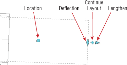
Location
The location glyph moves the pipe both horizontally and vertically and will disconnect it from the adjoining fittings or appurtenances. Changing the location of a fitting or appurtenance will move the pipe and maintain the connection.
Deflection
The deflection glyph will change the angle at which the pipe sits in the adjoining fitting. When this glyph is active, you will see a fan-shaped guide indicating the allowable deflection from the fitting properties in the pressure network parts list. You are able to move the pipe beyond the guide, but will receive design check errors when analyzing the network. You will take a closer look at design checks later in this chapter.
Continue Layout
Continue Layout will help you pick up where you left off when working with pressure pipes. When you use this glyph from the end of a pipe, it will create a bend using the elbows from your pressure parts list. When you use this grip from a fitting or appurtenance, you are restricted to creating your pipe within the object's deflection tolerance.
Lengthen
Lengthen will allow you to stretch or shorten a pipe. When used with dynamic input, you can set pipes to a specific desired 3D length. See the section on working with pipes and dynamic input earlier in the section “Editing with the Network Layout Tools Toolbar.”
As shown in Figure 14.74, you will encounter more glyphs when working with fittings and appurtenances.
Figure 14.74 Glyphs on a Tee fitting
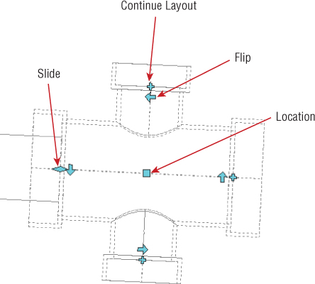
Slide
The slide glyph is similar to lengthen, but can modify a pipe's length when a fitting or appurtenance is already attached.
Flip
The flip glyph will mirror the part at its center. Flip glyphs are especially handy when working with Tees, as it is often necessary to change the outlet direction of a Tee after it is inserted. Be cautious when using the flip glyph with elbows, since it may disconnect the adjoining pipe.
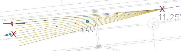
In this exercise, you will create a pressure network. Use the X's as a guide for placement, but don't worry if your pipe network is slightly off from the guides. Due to the 3D nature of the pipes, the restrictions on placement angles within the pressure network parts, and object snap behavior, duplicating an example network exactly would be quite tedious. Get a feel for the pressure network creation tools and have fun! You need to have completed the previous exercise before continuing.
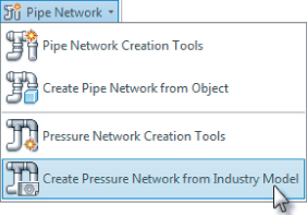
Figure 14.75 Selecting Pressure Network Creation Tools
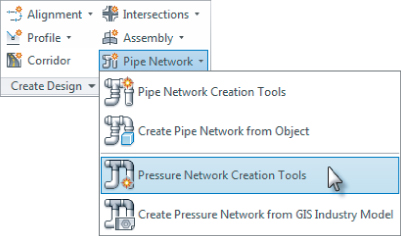
Figure 14.76 Creating your new Watermain system using pressure pipe network tools
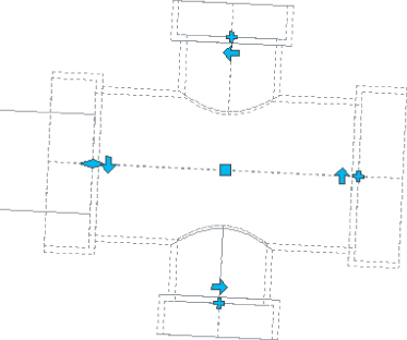
Figure 14.77 The Pressure Network Plan Layout toolbar
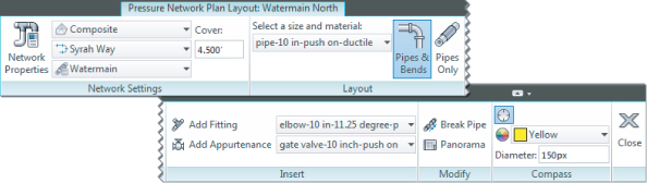
Figure 14.78 The pressure pipe fitting glyph reflects your elbow angles.

Figure 14.79 Use the deflection glyph to move the pipe.
![]()
Figure 14.80 Add fitting to the end of the pipe
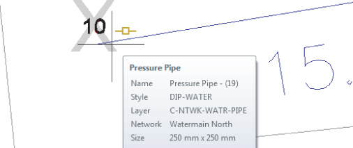
Figure 14.81 Disconnecting the part in preparation for rotating it
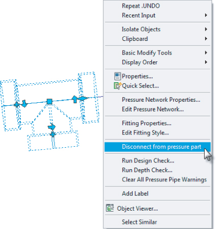
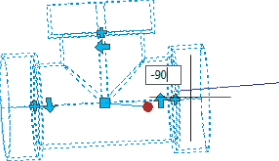
Figure 14.82 Rotate the tee to correct its position before reconnecting.
![]()
![]()
![]()
Pressure Pipe Networks in Profile View
Pressure pipe networks can do things in profile view that gravity pipes cannot. With pressure pipes, the profile view can be used to add on to the pipe layout, change straight pipes to curves, and delete parts from the project altogether. To these tools, select any pressure part and from the Pressure Networks contextual tab ⇒ Modify panel, pick Edit Network ⇒ Profile Layout Tools, as shown in Figure 14.83.
Figure 14.83 Locating the Profile Layout Tools

In the following exercise, you will draw the pressure pipe network in profile view and modify the layout using the Follow Surface command.
Figure 14.84 Pressure network in profile
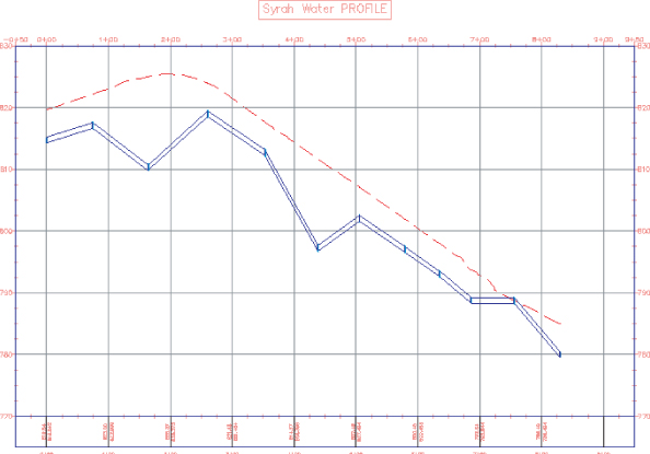
Figure 14.85 Pressure Network Profile Layout contextual tab

![]()
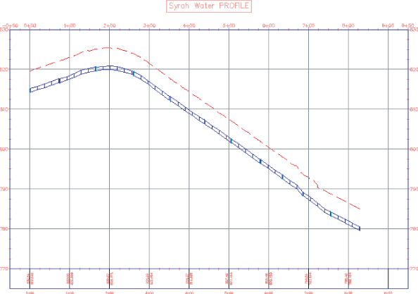
Figure 14.86 Pressure pipe following the surface
Design Checks
Pressure networks differ from the networks you created earlier in this chapter. Since the fluid in a pressure network can go uphill, the rules you saw in gravity systems no longer apply. The main concerns for a pressure network are pressure loss and depth of cover.
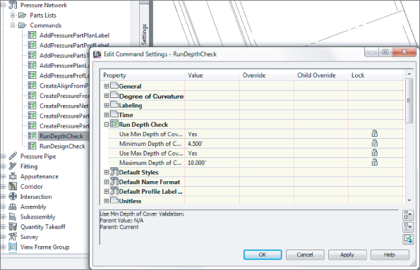
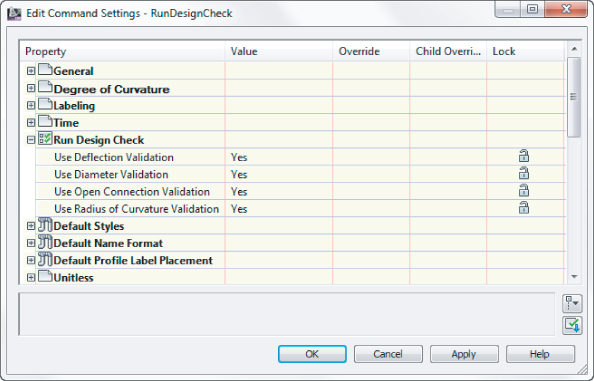
You can locate the depth check values on the Settings tab of Toolspace. Locate the Pressure Network branch and expand the Commands listing. Double-click RunDepthCheck to edit the command settings. A dialog like that in Figure 14.87 will open.
Figure 14.87 Edit the RunDepthCheck command settings to validate your design.
Civil 3D will not compute the pressure loss at each junction, but you can set an acceptable range of values for pipe bends and radius of curvature for curved pipes. Deflection Validation settings are found under RunDesignCheck, as shown in Figure 14.88.
Figure 14.88 Turning on deflection validation settings
Once you have created your pressure network, you should check your initial design for flaws. From the Pressure Networks contextual tab, you can check your design to see if it meets the requirements you set up in the command settings.
![]()
The depth check verifies that all pipes and fittings are within the acceptable range of values for depth.
![]()
Design Check will check for improperly terminating pipes, mismatched pipe and fitting diameters, any curved pipe whose radius has exceeded acceptable values, and pipes that have exceeded the maximum deflection you set up in the parts list.
In the following exercise, you will modify command settings and run a depth check on the pipe network:
Figure 14.89 Depth Check result in plan (top) and profile (bottom)

Part Builder
Part Builder is an interface that allows you to build and modify pipe network parts. You access Part Builder by selecting the drop-down list under Create Design from the Home tab. At first, you may use Part Builder to add a few missing pipes or structure sizes. As you become more familiar with the environment, you can build your own custom parts from scratch.
There is currently no tool available for creating custom pressure network parts, so this section only applies to gravity networks.
![]()
- Do I really understand pipes and structures well enough to tackle this? Is it worth taking extra time from a billable project to learn this feature?
- Is the part I need unique and not available from another source (such as http://www.cad-1.com/Solutions.aspx?id=1&SoftwareId=42)?
This section is intended to be an introduction to Part Builder and a primer in some basic skills required to navigate the interface. It isn't intended to be a robust “how-to” for creating custom parts. Civil 3D includes three detailed tutorials for creating three types of custom structures. The tutorials lead you through creating a cylindrical manhole structure, a drop inlet manhole structure, and a vault structure. You can find these tutorials by going to Help ⇒ Tutorials and then navigating to Part Builder Tutorials.
C:ProgramDataAutodeskC3D 2013enuPipes Catalog
The parts in the Civil 3D pipe network catalogs are parametric. Parametric parts are dynamically sized according to a set of variables, or parameters. In practice, this means you can create one part and use it in multiple situations.
For example, in the case of circular pipes, if you didn't have the option of using a parametric model, you'd have to create a separate part for each diameter of pipe you wanted, even if all other aspects of the pipe remained the same. If you had 10 pipe sizes to create, that would mean 10 sets of partname.dwg, partname.xml, and partname.bmp files, as well as an opportunity for mistakes and a great deal of redundant editing if one aspect of the pipe needed to change.
Fortunately, you can create one parametric model that understands how the different dimensions of the pipe are related to each other and what sizes are allowable. When a pipe is placed in a drawing, you can change its size. The pipe will understand how that change in size affects all the other pipe dimensions such as wall thickness, outer diameter, and more; you don't have to sort through a long list of individual pipe definitions.
Part Builder Orientation
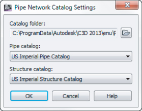
Each drawing “remembers” which part catalog it is associated with. If you're in a metric drawing, you need to make sure the catalog is mapped to metric pipes and structures, whereas if you're in an Imperial drawing, you'll want the Imperial catalog. By default, the Civil 3D templates should be appropriately mapped, but it's worth the time to check. Set the catalog by changing to the Home tab and selecting the drop-down list on the Create Design panel. Verify the appropriate folder and catalog for your drawing units in the Pipe Network Catalog Settings dialog (see Figure 14.90), and you're ready to go.
Figure 14.90 Choose the appropriate folder and catalog for your drawing units.
Understanding the Organization of Part Builder
The vocabulary used in the Part Builder interface is related to the vocabulary in the HTML catalog interface that you examined in the previous section, but there are several differences that are sometimes confusing.
![]()
Open Part Builder by going to the Home tab ⇒ Create Design panel and selecting the Part Builder icon from the drop-down list.
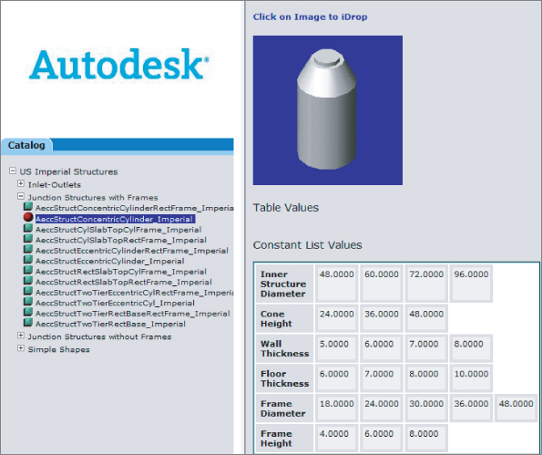
The first screen that appears when you start the Part Builder is Getting Started – Catalog Screen (see Figure 14.91).
Figure 14.91 The Getting Started – Catalog Screen

At the top of this window is a drop-down menu for selecting the part catalog. Depending on what you need to modify, you can set this to ether Pipe or Structure. Once you pick the catalog type, you will see the main catalog name. In Figure 14.91, you see US Imperial Pipe Catalog.
Below the part catalog is a listing of chapters. In Part Builder vocabulary, a chapter is a grouping based on the shape. Inside the chapters you will see the part families listed. The US Imperial Pipe Catalog has four default chapters:
- Circular Pipes
- Egg-Shaped Pipes
- Elliptical Pipes
- Rectangular Pipes
You can create new chapters for different-shaped pipes, such as Arch Pipe.
The US Imperial Structure Catalog also has four default chapters: Inlets-Outlets, Junction Structures With Frames, Junction Structures Without Frames, and Simple Shapes. You can create new chapters for custom structures. You can expand each chapter folder to reveal one or more part families. For example, the US Imperial Circular Pipe Chapter has six default families:
- Concrete Pipe
- Corrugated HDPE Pipe
- Corrugated Metal Pipe
- Ductile Iron Pipe
- HDPE Pipe
- PVC Pipe
Pipes that reside in the same family typically have the same parametric behavior, with only differences in size.
As Table 14.1 shows, a series of buttons on the Getting Started – Catalog Screen lets you perform various edits to chapters, families, and the catalog as a whole.
Table 14.1 The Part Builder catalog tools
| Icon | Function |
|
|
The New Parametric Part button creates a new part family. |
|
|
The Modify Part Sizes button allows you to edit the parameters for a specific part family. |
|
|
The Catalog Regen button refreshes all the supporting files in the catalog when you've finished making edits to the catalog. |
|
|
The Catalog Test button validates the parts in the catalog when you've finished making edits to the catalog. |
|
|
The New Chapter button creates a new chapter. |
|
|
The Delete button deletes a part family. Use this button with caution, and remember that if you accidentally delete a part family, you can restore your backup catalog as mentioned in the beginning of this section. |
Exploring Part Families
The best way to get oriented to the Part Builder interface is to explore one of the standard part families. In this case,
![]()
Figure 14.92 Content builder toolspace and related DWG file

The Part Builder task pane, or Content Builder (Figure 14.93), is well documented in the Civil 3D User's Guide. Please refer to the User's Guide for detailed information about each entry in Content Builder.
Figure 14.93 Content Builder
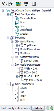
Adding a Part Size Using Part Builder
The hypothetical municipality requires a 12″ (300 mm) sanitary sewer cleanout. After studying the catalog, you decide that Concentric Cylindrical Structure NF is the appropriate shape for your model, but the smallest inner diameter size in the catalog is 48″ (1200 mm). The following exercise gives you some practice in adding a structure size to the catalog—in this case, adding a 12″ (300 mm) structure to the US Imperial Structures catalog.
You can make changes to the US Imperial Structures catalog from any drawing that is mapped to that catalog, which is probably any imperial drawing you have open, as follows:
Figure 14.94 Examining available part sizes

![]()
Figure 14.95 Add the 12″ (300 mm) value to the Edit Values dialog
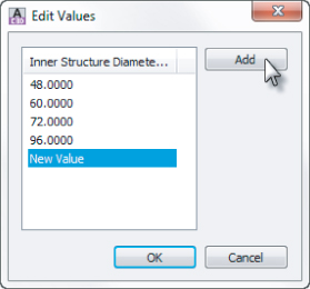
You're back in your original drawing. If you created a new parts list in any drawing that references the US Imperial Structures catalog, the 12″ (300 mm) structure would now be available for selection.
Sharing a Custom Part
You may find that you need to go beyond adding pipe and structure sizes to your catalog and build custom part families or even whole custom chapters. Perhaps instead of building them yourself, you're able to acquire them from an outside source.
The following section can be used as a reference for adding a custom part to your catalog from an outside source, as well as sharing custom parts that you've created. The key to sharing a part is to locate the three files mentioned earlier.
Adding a custom part size to your catalog requires these steps:
Adding an Arch Pipe to Your Part Catalog
This exercise will teach you how to add a premade custom part to your catalog. You can make changes to the US Imperial Pipes catalog from any drawing that is mapped to that catalog, which is probably any imperial drawing you have open.
C:ProgramDataAutodeskC3D 2013enuPipes CatalogUS Imperial Pipes

(C:ProgramDataAutodeskC3D 2013enuPipes CatalogMetric Pipes)
C:ProgramDataAutodeskC3D 2013enuPipes CatalogUS Imperial
PipesImperial Pipes.htm
The Bottom Line
Create a pipe network by layout.
After you've created a parts list for your pipe network, the first step toward finalizing the design is to use Pipe Network By Layout.
Master It
Open the MasteringPipes.dwg or Mastering pipes_METRIC.dwg file. From the Home tab ⇒ Create Design panel ⇒ Pipe Network, select Pipe Network Creation Tools to create a sanitary sewer pipe network. Use the Composite surface, and name only structure and pipe label styles. Don't choose an alignment at this time. Create 8″ (200 mm) PVC pipes and concentric manholes. There are blocks in the drawing to assist you in placing manholes. Begin at the START HERE marker, and place a manhole at each marker location. You can erase the markers when you've finished.
Create an alignment from network parts and draw parts in profile view.
Once your pipe network has been created in plan view, you'll typically add the parts to a profile view based on either the road centerline or the pipe centerline.
Master It
Continue working in the MasteringPipes.dwg (Mastering pipes_METRIC.dwg) file. Create an alignment from your pipes so that station zero is located at the START HERE structure. Create a profile view from this alignment, and draw the pipes on the profile view.
Label a pipe network in plan and profile.
Designing your pipe network is only half of the process. Engineering plans must be properly annotated.
Master It
Continue working in the MasteringPipes.dwg (Mastering pipes_METRIC.dwg) file. Add the Length Description And Slope style label to profile pipes and the Data With Connected Pipes (Sanitary) style to profile structures. Add the alignment created in the previous Master It to all pipes and structures.
Create a dynamic pipe table.
It's common for municipalities and contractors to request a pipe or structure table for cost estimates or to make it easier to understand a busy plan.
Master It
Continue working in the MasteringPipes.dwg (Mastering pipes_METRIC.dwg) file. Create a pipe table for all pipes in your network. Use the default table style.