Chapter 3
Points
In the previous chapter, “Survey,” you looked at a specific method for bringing in points and figures. In this chapter, you will take a closer look at creating and organizing points.
The foundation of any civil engineering project is the simple point, frequently referred to as a shot. Most commonly, points are used to identify the location of existing features, such as trees and property corners; topography, such as ground shots; or stakeout information, such as road geometry points. However, points can be used for much more. This chapter will both focus on traditional point uses and introduce ideas to apply the dynamic power of point editing, labeling, and grouping to other applications.
In this chapter, you will learn to:
- Import points from a text file using description key matching
- Create a point group
- Export points to LandXML and ASCII format
- Create a point table
Anatomy of a Point
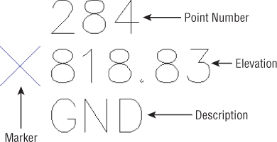
AutoCAD® Civil 3D® points (see Figure 3.1) are intelligent objects that represent x, y, and z locations in space. Each point has a unique number and, optionally, a unique name that can be used for additional identification and labeling.
Figure 3.1 A typical point object showing a marker, a point number, an elevation, and a description
COGO Points vs. Survey Points
In Chapter 2, you imported survey data that contained points. Points brought in through the methods described in Chapter 2 are referred to as survey points. In this chapter, you will import points from a delimited text file and place them in CAD using the point creation tools. Points created in this manner are referred to as COGO points. Figure 3.2 shows the context tab differences between points brought in as COGO points (top) and points brought in through a database (bottom).
Figure 3.2 The context-sensitive Ribbon reflects similarities and differences between COGO points (top) and survey points (bottom).

The differences between COGO points and survey points are subtle but important to note. A COGO point is unlocked by default — meaning it can readily be edited. A survey point, on the other hand, must be unlocked if a user wishes to edit the point. A survey point stays tied to the database from which it came, whereas a COGO point maintains no tie to the originating text file or object it was created against. Regardless of their origin, both COGO points and survey points obey the principles outlined in this chapter.
Creating Basic Points
![]()
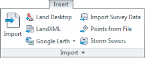
You can create points many ways, using the Points menu in the Create Ground Data panel on the Home tab. Points can also be imported from text files or external databases or converted from AutoCAD, Land Desktop, or SoftDesk point objects.
Point Settings
Point settings are our first glimpse at what is known as command settings. All Civil 3D objects have command settings tucked away in the Settings tab of Toolspace. In the case of points, it is handy to have these settings readily available for on-the-fly modifications. Whether or not the changes you make on the fly are remembered the next time you create points depends on your template settings.
To make sure that the settings you change will hold every time, you create points:
Figure 3.3 In your Civil 3D template, make sure Save Command Changes To Settings is set to Yes for Points.

If you explore the command settings further, you will see the options for Default Layer and Points Creation. By setting this to Yes, you are ensuring that changes you make at the tool level will also be reflected at the command level.
To access the Create Points toolbar:
Default Layer
For most Civil 3D objects, the object layer is established in the drawing settings. In the case of points, the default object layer is set in the command settings for point creation and can be changed in the Create Points dialog (see Figure 3.4).
Figure 3.4 Verify the point object layer before creating points.

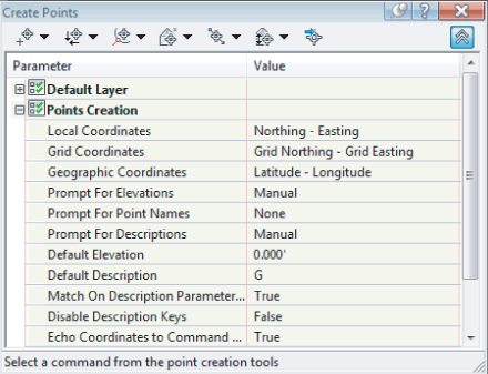
Prompt for Elevations, Names, and Descriptions
When creating points in your drawing, you have the option of being prompted for elevations, names, and descriptions (see Figure 3.5). Initially, the Default description is blank. In many cases, you'll want to leave these options set to Manual. The command line will ask you to assign an elevation and description for every point you create. It is best to avoid using the Point Name option, as described later in this section.
Figure 3.5 You can change the elevation, point name, and description settings from Manual to Automatic. You can also use the None option to omit this information.
If you're creating a batch of points that have the same description or elevation, you can change the Prompt toggle from Manual to Automatic and then provide the description and elevation in the default cells. For example, if you're setting a series of trees at an elevation of 10′, you can establish settings as shown in Figure 3.6.
Figure 3.6 Default settings for placing tree points at an elevation of 10'

Note that these settings only apply to points created from this toolbar. The settings do not affect the elevation or description of points imported from a file.
Importing Points from a Text File
![]()
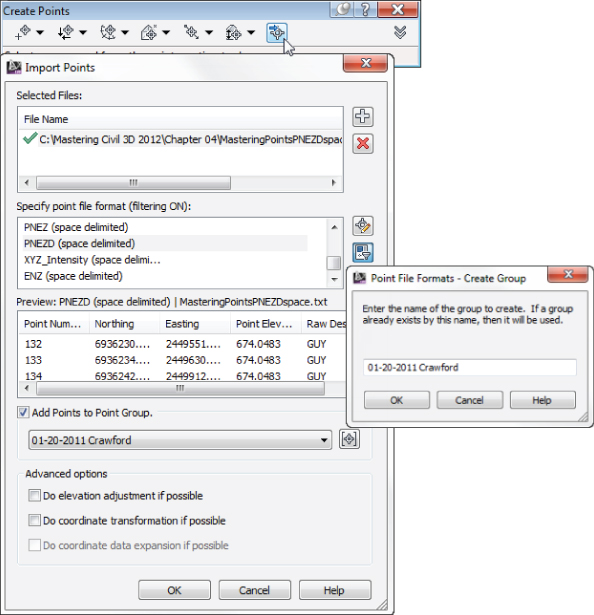
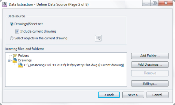
One of the most common means of creating points in your drawing is to import an external text file (see Figure 3.7).
Figure 3.7 The Import Points and the Point File Formats dialogs
![]()
To add a file to your Import Points dialog, click the plus sign to browse. You can add multiple files at once if they are in the same point format — such as PNEZD (Comma Delimited). The import process supports most text formats as well as Microsoft Access database (MDB) files. Later in this chapter you will experience adding your own text format.
When your file is listed in the top of the dialog box, a green check mark will indicate that Civil 3D can parse the information. Be careful, though, because Civil 3D does not know the difference between a Northing and an Easting or a point number and an elevation. You still need to select the correct file format.
![]()
The file format filter is there to help you. Civil 3D recognizes how the file is delimited (i.e., tab, comma, space) and only shows you the formats that apply. If you don't want the help, you can turn the filtering off by clicking the Filter icon.
![]()
If the file format you need is not available, or you wish to use the adjustment and transformation capabilities, you can do so by clicking the Manage Formats button.
You can make an elevation adjustment if the point file contains additional columns for thickness, Z+, or Z-. You can add these columns as part of a custom format. See the AutoCAD Civil 3D 2013 User's Guide section “Using Point File Format Properties to Perform Calculations” for more details.
You can perform a coordinate system transformation if a coordinate system has been assigned both to your drawing (under the drawing settings) and as part of a custom point format. In this case, the program can also do a coordinate data expansion, which calculates the latitude and longitude for each point.
A common use of the formats is to create a point file format for importing a name-based point file. In the following example, you will create a new file format to accommodate names (instead of point numbers):
Figure 3.8 A completed and tested new point file format

The new file format will remain in case you need it. To compare your work with a completed example, see Format Example_FINISHED.dwg at the book's web page.
Importing a Text File of Points
In this exercise, you'll learn how to import a TXT file of points into Civil 3D:
![]()
You may have to use Zoom Extents to see the imported points. (Hint: Double-click your middle mouse wheel for zooming extents.)
Converting Points from Non–Civil 3D Sources
Civil 3D contains several tools for migrating legacy point objects to the current version. The best results are often obtained from an external point list, such as a text file, LandXML, or an external database. However, if you come across a drawing that contains the original Land Desktop, SoftDesk, AutoCAD, or other types of point objects, tools, and techniques are available to convert those objects into Civil 3D points.
A Land Desktop point database (the Points.mdb file found in the COGO folder in a Land Desktop project) can be directly imported into Civil 3D in the same interface in which you'd import a text file.
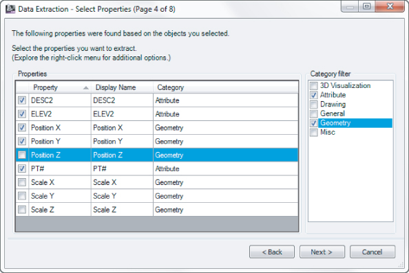
Land Desktop point objects, which appear as AECC_POINTs in the AutoCAD Properties palette, can also be converted to Civil 3D points (see Figure 3.9). Upon conversion, this tool gives you the opportunity to assign styles, create a point group, and more.
Figure 3.9 The Convert Land Desktop Points option (left) opens the Convert Autodesk Land Desktop Points dialog.

Occasionally, you'll receive AutoCAD point objects drawn at elevation from aerial topography information or other sources. It's also not uncommon to receive SoftDesk point blocks from other surveyors. Both of these can be converted to or replaced by Civil 3D points by going to the Home tab ⇒ Create Ground Data panel ⇒ Points and picking one of the many point conversion options there (see Figure 3.9).
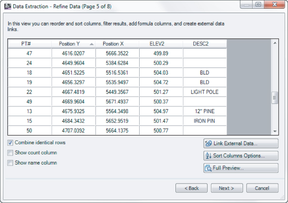
![]()
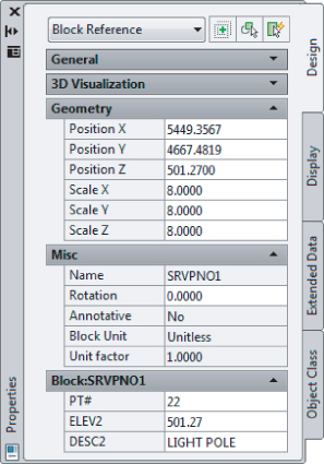

- Point number (PT#)
- Elevation (ELEV2)
- Description (DESC2)
- Position X
- Position Y
Converting Points
In this exercise, you'll convert Land Desktop point objects and AutoCAD point entities into Civil 3D points:
A Closer Look at the Create Points Toolbar
![]()
In Civil 3D 2013, you can find point-creation tools directly under the Points drop-down on the Create Ground Data panel of the Home tab, as well as in the Create Points toolbar. The toolbar is modeless, which means it stays on your screen even when you switch between tasks. Figure 3.10 shows the toolbar with the point-creation methods labeled.
Figure 3.10 The Create Points toolbar
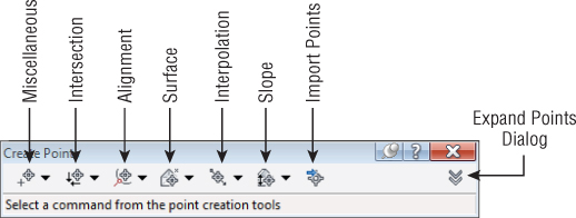
As you place points using these tools, a few general rules apply to all of them. If you place a point on an object with elevation, the point will automatically inherit the elevation of the object. If you use the surface options, the point will automatically inherit the elevation of the surface you choose.
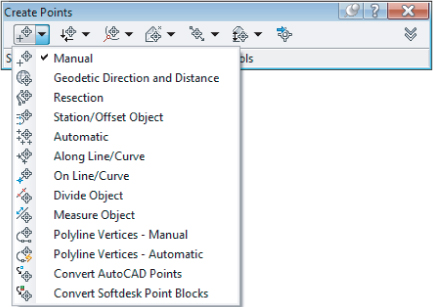
Miscellaneous Point-Creation Options
The options in the Miscellaneous category are based on manually selecting a location or on an AutoCAD entity, such as a line, pline, and so on. Some common examples include placing points at intervals along a line or polyline, as well as converting SoftDesk points or AutoCAD points (see Figure 3.11).
Figure 3.11 Miscellaneous point-creation options
Intersection Point-Creation Options
The options in the Intersection category allow you to place points at a certain location without having to draw construction linework. For example, if you needed a point at the intersection of two bearings, you could draw two construction lines using the Bearing Distance transparent command, manually place a point where they intersect, and then erase the construction lines. Alternatively, you could use the Direction/Direction tool in the Intersection category (see Figure 3.12).
Figure 3.12 Intersection point-creation options

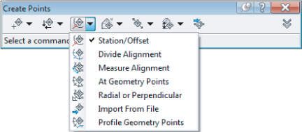
Alignment Point-Creation Options
The options in the Alignment category are designed for creating stakeout points based on a road centerline or other alignments. You can also set Profile Geometry points along the alignment using a tool from this menu. See Figure 3.13.
Figure 3.13 Alignment point-creation options
Surface Point-Creation Options
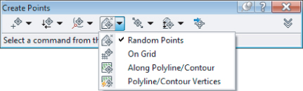
The options in the Surface category let you set points that harvest their elevation data from a surface. Note that these are points, not labels, and therefore aren't dynamic to the surface. You can set points manually, along a contour or a polyline, or in a grid. See Figure 3.14.
Figure 3.14 Surface point-creation options
Interpolation Point-Creation Options
The Interpolation category lets you fill in missing information from survey data or establish intermediate points for your design tasks. For example, suppose your survey crew picked up centerline road shots every 100′ (30 m), and you'd like to interpolate intermediate points every 25′ (8 m). Instead of doing a manual slope calculation, you could use the Incremental Distance tool to create additional points (see Figure 3.15).
Figure 3.15 The Interpolation point-creation options

Slope Point-Creation Options
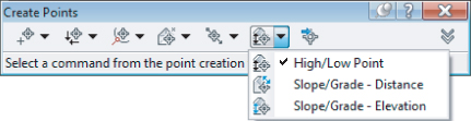
The Slope category allows you to set points between two known elevations by setting a slope or grade. Similar to the options in the Interpolation and Intersection categories, these tools save you time by eliminating construction geometry and hand calculations (see Figure 3.16).
Figure 3.16 Slope point-creation options
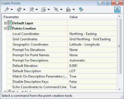
Creating Points
In this exercise, you'll learn how to create points along a parcel segment and along a surface contour:
Figure 3.17 Point-creation settings in the Create Points dialog
![]()
![]()
![]()
![]()
![]()
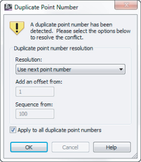
Add An Offset
This option will allow you to add a value to all incoming points. Specifying an offset of 1000 would turn 1, 2, and 5 into 1001, 1002, and 1005.
Merge
If the existing point has a description but no elevation, and the incoming point has an elevation and no description, Civil 3D will fill in the gaps with the incoming information. If there is no missing data and the coordinates are identical, the incoming point is ignored. Be careful using merge; it will behave similar to the Overwrite option if the coordinates don't match.
Overwrite
This option deletes the existing point and replaces it with the incoming point.
Sequence From
This option will restart the numbering at a higher value. Unlike adding an offset, the original point number is ignored. Setting a sequence from 1000 would turn 1, 2, and 5 into 1001, 1002, and 1003.
Use Next Point Number
The default option, Use Next Point Number, finds the next available point number and imports the point.
Basic Point Editing
Despite your best efforts, points will often be placed in the wrong location or need additional editing after their initial creation. Points may need to be rotated as a group to match a different horizontal datum. Points may need to be raised or lowered to match a different benchmark.
Physical Point Edits
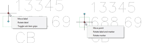
Points can be moved, copied, rotated, deleted, and more using standard AutoCAD commands and grip edits. When you pause your cursor over a grip, a special grip menu will appear with different options. Figure 3.18 (left) shows the grip menu options for the label. Figure 3.18 (right) shows the options available directly on the point. Using the options shown here, you can move the point and rotate it independently of the text and rotate the text label independently of the marker.
Figure 3.18 The top grip allows label modifications (left); the center grip allows marker modifications (right).
Panorama and Prospector Point Edits
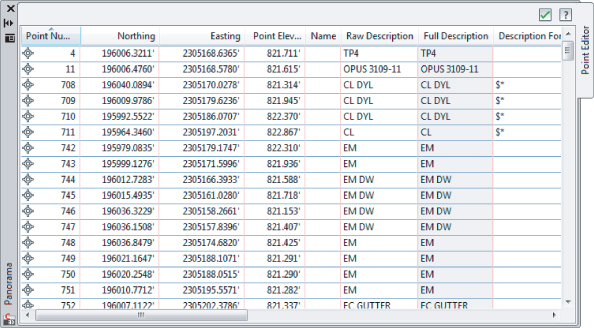
You can access many point properties through the Point Editor in Panorama:

Figure 3.19 Edit points in Panorama
You can access a similar interface in the Prospector tab of Toolspace by following these steps:
Figure 3.20 Prospector lets you view your entire Points collection at once.

Point Groups: Don't Skip This Section!
![]()
Working with point groups is one of the most powerful techniques you will learn from this chapter. Want to turn all your points off without touching layers? Make a point group! Want to move last week's survey up by the blown instrument height difference? Make a point group! Want to show all your Topo shots as dots rather than Xs? Want to prevent invert shots from throwing off your surface model? Point group! Point group!
A point group is a collection of points that has been filtered for a certain criterion. You can use any point property or combination of properties such as description, elevation, and point number, or you can select specific points in the drawing.
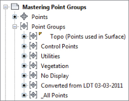
Civil 3D creates the _All Points group for you, which contains every point in the drawing. It cannot be renamed or deleted, or have its properties modified to exclude any points. Create point groups for collections of points you might wish to separate from others, as shown in Figure 3.21.
Figure 3.21 An example of useful point groups in Prospector
Point groups can (and should!) be created upon import of a text file, as shown previously in Figure 3.7. That way, if a problem comes to light about that group of points (such as incorrect instrument height) they can be isolated and dealt with apart from other points. Create a new point group by right-clicking on the main point group category and selecting New.
In this exercise, you'll learn how to use point groups to separate points into usable categories:
Figure 3.22 The Include tab of the Vegetation point group properties
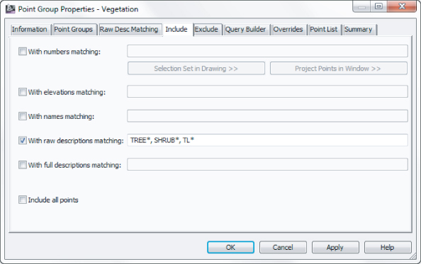
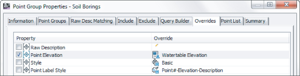
Figure 3.23 Overrides forces the styles to conform by point group rather than description key.
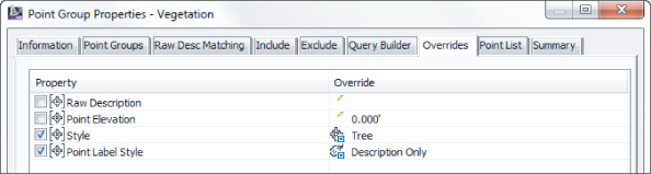
Figure 3.24 Most drawings should contain a NO DISPLAY point group with styles set to <none>.
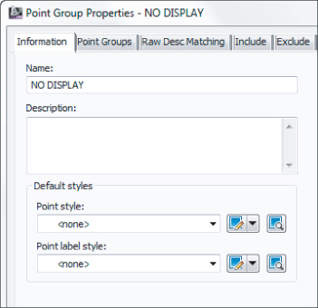
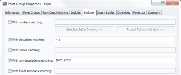
Figure 3.25 Use Exclude to create a Topo point group.
Best Practice: Control Point Display Using Point Groups Rather than Layers
Civil 3D drawings will have many layers in them. It is much easier to switch the display of the point groups rather than create layer states for each point visibility scenario.
A point can belong to more than one group at once. For instance, a water valve cover with elevation may be in a Topo group, a Utilities group, and the _All Points group. In these cases, the order in which the point group is displayed in Prospector determines which point group a point is “listening to” for its properties.
In this exercise, we will walk you through an example of how point group display order works:
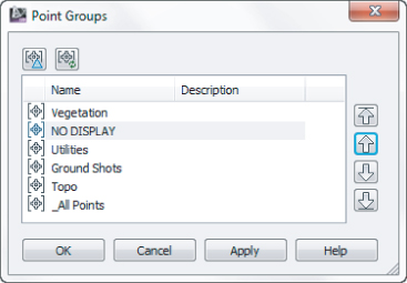
Figure 3.26 Select Point Groups ⇒ Properties to change point group display precedence.

Figure 3.27 The order in which the point groups appear in this list controls precedence.
Changing Point Elevations
Points placed on or along an object that has elevation will automatically inherit the object's elevation. Points placed with tools in the Surface flyout will automatically inherit the elevation of a surface model. If you have chosen to place points with manual elevation entry and press ![]() when prompted to specify an elevation, the elevation will be null (no elevation).
when prompted to specify an elevation, the elevation will be null (no elevation).
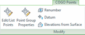
You are never stuck with a COGO point's elevation. They can be changed individually or as a group using the Panorama window. Additional tools are available for manipulating points (see Figure 3.28), in the COGO Point contextual tab that opens when you select a point object.
Figure 3.28 Point-editing commands in the Ribbon
![]()
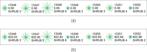
Elevations From Surface is an extremely handy tool for forcing points to a surface elevation (see Figure 3.29).
Figure 3.29 Shrub points as placed (a); shrub points moved up to surface elevation (b)
When you change the datum, you are most likely going to move a group of points' elevations. Right-click on the name of the point group in Prospector and select Edit Points. Panorama will appear for your point-editing delight.
Use Windows keyboard tricks to control which points are selected for modification. Pressing Ctrl+A will select all points in the Panorama listing, as shown in Figure 3.30. When you are done selecting points, right-click and choose Datum. The command line will prompt you to specify the change in elevation you require.
Figure 3.30 Right-click to access point modification tools from Panorama.

An interesting fact to note about description keys is that they take over styles and layers set elsewhere. For example, if your point placement options have a layer set but you place a point that matches a description key with a layer set to something different, the description key set “wins.” In the point group creation examples, you set the Overrides tab to have Style and Point Label Style selected (Figure 3.22). Those settings wrestle control of the styles away from the description key and into the hands of the point group.
Point Tables
You've seen some of the power of dynamic point editing; now let's look at how those dynamic edits can be used to your advantage in point tables.
Most commonly, you may need to create a point table for survey or stakeout data; it could be as simple as a list of point numbers, northing, easting, and elevation. These types of tables are easy to create using the standard point-table styles and the tools located in the Points menu under the Add Tables option.
![]()
Figure 3.31 Point Table Creation options

User-Defined Properties
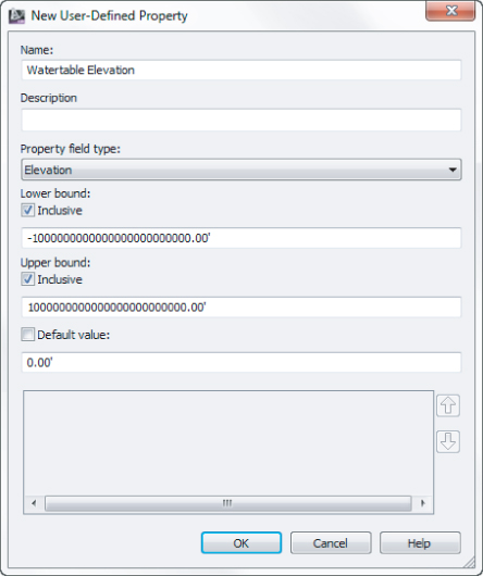
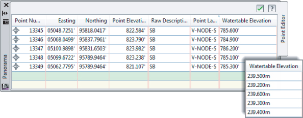
Standard point properties include items such as number, easting, northing, elevation, name, description, and the other entries you see when examining points in Prospector or Panorama. But what if you'd like a point to know more about itself?
It's common to receive points from a soil scientist that list additional information, such as groundwater elevation or infiltration rate. Surveyed manhole points often include invert elevations or flow data. Tree points may also contain information about species or caliber measurements. All this additional information can be added as user-defined properties to your point objects. You can then use user-defined properties in point labeling, analysis, point tables, and more.


The Bottom Line
Import points from a text file using description key matching.
Most engineering offices receive text files containing point data at some time during a project. Description keys provide a way to automatically assign the appropriate styles, layers, and labels to newly imported points.
Master It
Create a new drawing from _AutoCAD Civil 3D (Imperial) NCS.dwt (or _AutoCAD Civil 3D (Metric) NCS.dwt). Revise the Civil 3D description key set to contain only the parameters listed here:
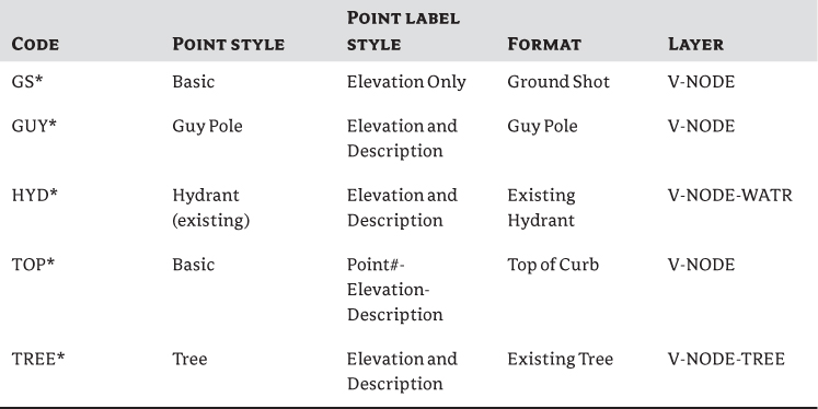
Import the PNEZD (space delimited) file Concord.txt (Concord_METRIC.txt). Confirm that the description keys made the appropriate matches by looking at a handful of points of each type. Do the trees look like trees? Do the hydrants look like hydrants?
Save the resulting file.
Create a point group.
Building a surface using a point group is a common task. Among other criteria, you may want to filter out any points with zero or negative elevations from your Topo point group.
Master It
Create a new point group called Topo that includes all points except those with elevations of zero or less. Use the DWG created in the previous Master It or start with Master_It.dwg (Master_It_METRIC.dwg).
Export points to LandXML and ASCII format.
It's often necessary to export a LandXML or ASCII file of points for stakeout or data-sharing purposes. Unless you want to export every point from your drawing, it's best to create a point group that isolates the desired point collection.
Master It
Create a new point group that includes all the points with a raw description of TOP. Export this point group via LandXML to a PNEZD comma-delimited text file.
Use the DWG created in the previous Master It or start with Master_It.dwg (Master_It_METRIC.dwg).
Create a point table.
Point tables provide an opportunity to list and study point properties. In addition to basic point tables that list number, elevation, description, and similar options, you can customize point table formats to include user-defined property fields.
Master It
Continue working in Master_It.dwg (Master_It_METRIC.dwg). Create a point table for the Topo point group using the PNEZD format table style.