Chapter 10
Basic Corridors
The corridor object is a three-dimensional model that combines the horizontal geometry of an alignment, the vertical geometry of a profile, and the cross-sectional geometry of an assembly.
Corridors range from extremely simple roads to complicated highways and interchanges, but aren't limited to just road travel ways. Corridors can be used to model many linear designs. This chapter focuses on building several simple corridors that can be used to model and design roads, channels, and trenches.
In this chapter, you will learn to:
- Build a single baseline corridor from an alignment, profile, and assembly
- Use targets to add lane widening
- Create a corridor surface
- Add an automatic boundary to a corridor surface
Understanding Corridors
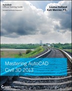
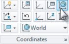
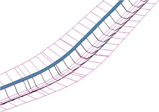
In its simplest form, a corridor combines an alignment, a profile, and an assembly (see Figure 10.1).
Figure 10.1 A corridor shown in 3D view
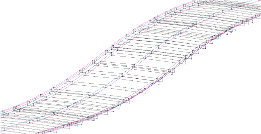
You can also build corridors with complex combinations of alignments, profiles, and assemblies to make complicated intersections, interchanges, or branching streams (see Figure 10.2).
Figure 10.2 An intersection modeled with a corridor
The horizontal properties of the alignment, the vertical properties of the profile, and the cross-sectional properties of the assembly are merged together to form a dynamic model that can be used to build surfaces, sample cross sections, generate quantities, and much more.
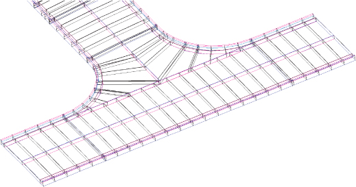
Most commonly, corridors are thought of as being used to model roads, but they can also be adapted to model berms, streams (see Figure 10.3), trails, and even parking lots.
Figure 10.3 A stream modeled with a corridor
Corridor Components
![]()
First, let's look at some important corridor components you will want to become familiar with before proceeding. Baseline, regions, assemblies, frequency, and targets are all parts of a corridor that you will encounter even on your first design.
Baseline
The first component for any corridor is a baseline. The baseline is actually composed of two AutoCAD® Civil 3D® objects, an alignment providing the horizontal layout and a profile providing the vertical layout. The baseline generates the backbone skeleton on which the assembly can hang.
In most examples in this chapter, the baseline will correspond to the centerline alignment with a profile representing the elevation at the crown of a proposed road. However, this is not always the case, as we will explore in more depth in Chapter 11, “Advanced Corridors, Intersections, and Roundabouts.” As your designs become more detailed, you may have corridors with multiple baselines.
Regions
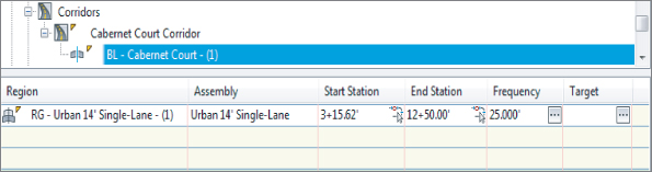
When the geometry along a baseline changes enough to warrant a new assembly, a new region is needed. Regions specify the station range where a specific assembly is applied to the design. There may be many regions along a baseline to accommodate design geometry but the regions may not overlap. Therefore, each region has a start station and an end station with the end station of one region often matching the start station of the next region.
Assemblies
Marker points and links are coded into the subassemblies that comprise the assembly, as you saw in Chapter 8, “Assemblies and Subassemblies.” Assemblies are the third Civil 3D object that is required to generate the corridor by providing cross-sectional information to be applied along some or all of the length of the baseline. Figure 10.4 shows a symmetric typical roadway assembly which consists of lanes, curbs, sidewalks, and daylight links.
Figure 10.4 Typical roadway assembly

Frequency
Frequency refers to how often the assembly is applied to the corridor design. You can set the frequency distance for the corridor as a whole, but in most cases, you should apply it at the region level.
The frequency value will vary depending on the situation. The default frequencies of the stock Civil 3D templates are 25′ in Imperial units and 20 m for metric units. But like many of the settings in Civil 3D, these defaults can be changed in your drawing or template settings by using the following simple steps:
In addition to the frequencies based on the alignment or profile entity, Civil 3D can place frequency lines at special stations such as horizontal geometry stations, superelevation critical stations, profile geometry stations, profile high/low stations, or offset geometry stations. You can also create additional frequency stations for things like driveways or culvert crossings.
Targets
As you learned in Chapter 8, there are three types of targets that an assembly can reference: a target surface, a target elevation, and a target offset. Some targets are optional whereas others are required. You will want to reference the help files, for the various subassemblies that are used in the assembly, to determine further information on what types of targets you may need or want.
Corridor Feature Lines
After a corridor is created, you will see a series of lines running parallel (or mostly parallel) to the alignment; these lines are called corridor feature lines. Corridor feature lines, sometimes referred to simply as feature lines, are the result of Civil 3D playing connect-the-dots with marker points between the frequency lines.
Everywhere the assembly contains a named marker point, Civil 3D creates a feature line with the same name.
These special feature lines are the third dimension that takes a corridor from being simply a collection of cross sections to being a model with meaningful flow (see Figure 10.5).
Figure 10.5 The anatomy of a corridor

Later on in this chapter, we will take a closer look at corridor feature lines.
This exercise gives you hands-on experience in building a corridor model from an alignment, a profile, and an assembly:
Figure 10.6 The Create Corridor dialog

Figure 10.7 The Baseline And Region Parameters dialog

Most of the other settings have already been set from the information you provided in the Create Corridor dialog, but let's take a few minutes to look at some of the settings in the Baseline And Region Parameters dialog.
9. Click the ellipsis button in the Frequency column in the first row associated with the baseline (BL) to display the Frequency To Apply Assemblies dialog.
Figure 10.8 The Frequency To Apply Assemblies dialog

Figure 10.9 The Target Mapping dialog
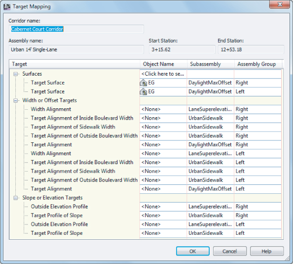
Figure 10.10 Corridor errors in the Panorama

![]()
If Panorama did not automatically display, from the Home tab ⇒ Palettes expanded panel, choose Event Viewer.
Figure 10.11 A portion of the nearly completed corridor

Figure 10.12 A “waterfall” at the end of the alignment viewed in the Object Viewer
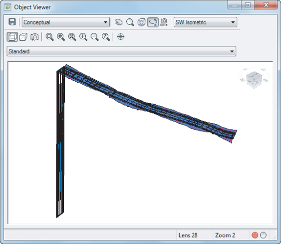

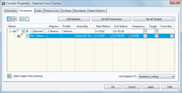
Figure 10.13 Corridor Properties dialog, Parameters tab
A quick look in the Object Viewer should reveal that the waterfall is gone. When this exercise is complete, you may close the drawing. A finished copy of this drawing is available from the book's website with the filename RoadCorridor_FINISHED.dwg or RoadCorridor_METRIC_FINISHED.dwg.
Rebuilding Your Corridor
A corridor is a dynamic model — which means that if you modify any of the objects used to create the corridor, the corridor must be updated to reflect those changes. For example, if you make a change to the Finished Ground profile, the corridor needs to be rebuilt to reflect the new design. The same principle applies to changes to alignments, assemblies, target surfaces, and any other corridor ingredients or parameters.
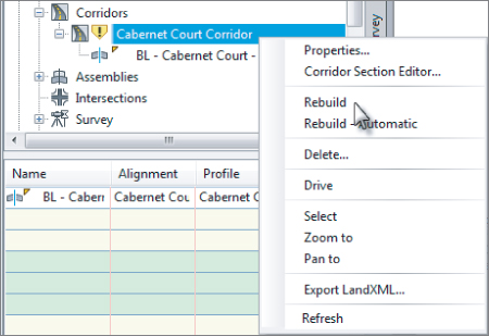
You can access the Rebuild command by right-clicking on the corridor name from Prospector, as shown in Figure 10.14.
Figure 10.14 Right-click the corridor name in the Corridor collection in Prospector to rebuild it.
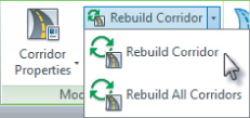
You can also rebuild the corridor or rebuild all corridors by selecting the corridor object and choosing Rebuild Corridor or Rebuild All Corridors from the contextual tab ⇒ Modify Corridor panel, as shown in Figure 10.15.
Figure 10.15 Rebuilding the corridor from the contextual tab
Corridor Tips and Tweaks
Your corridor may not be perfect on your first iteration of the design. Get comfortable getting into and working with the Parameters tab of the Corridor Properties dialog. This tab will be your first stop to examine what might be amiss in your corridor model.
Whether you are building your first corridor or your five hundredth, odds are good that you will run into one of the following common issues:
Problem
Your corridor seems to fall off a cliff, meaning the beginning or ending station of your corridor drops down to elevation zero.
Typical Cause
The range of your corridor is longer than the design profile.
Fix
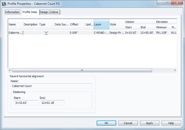
This is exactly what you ran into in the first exercise. The corridor takes the initial station range from your alignment. However, most designers don't tie into existing ground at the exact alignment start and end stations, so you need to adjust the corridor stations accordingly.
Figure 10.16 Check your Profile Properties dialog to verify the station range of the design profile.
Problem
Your corridor seems to take longer to build and has irregular frequency stations. Also, your daylighting may not extend out to where you expect it (see Figure 10.17).
Figure 10.17 An example of unexpected corridor frequency

Typical Cause
You accidentally chose the Existing Ground profile instead of the Finished Ground profile for your baseline profile. Most corridors are set up to place a frequency line at every vertical geometry point, and a profile, such as the Existing Ground profile, has many more vertical geometry points than a layout profile (in this case, the Finished Ground profile). These additional points on the Existing Ground profile are the cause of the unexpected sample lines and flags that something is wrong.
Fix
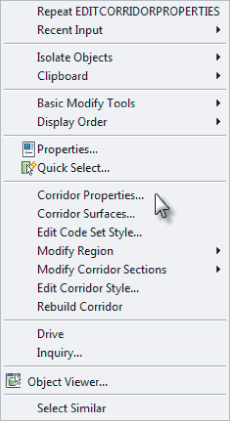
Always use care to choose the correct profile. Either physically select the profile on screen or make sure your naming conventions clearly define your finished grade as finished grade. If your corridor is already built, select the corridor, right-click, and choose Corridor Properties, as shown in Figure 10.18. On the Parameters tab of the Corridor Properties dialog, change the profile from the existing ground profile to the finished ground profile.
Figure 10.18 The right-click menu available on the corridor object
Adding a surface target throws another variable into the mix. Here is a list of some of the most typical problems new users face and how to solve them:
Problem
Your corridor doesn't show daylighting even though you have a daylight subassembly on your assembly. You may also get an error message in Event Viewer.
Typical Cause
You forgot to set the surface target when you created your corridor.
Fix
If your corridor is already built, select the corridor, right-click, and choose Corridor Properties. On the Parameters tab of the Corridor Properties dialog, click the Set All Targets button. The Target Mapping dialog opens, and its first category is Surfaces. Click the <Click here to set all> text in the Object Name column field to display the Pick A Surface dialog. In this dialog, you can choose a surface for the daylight subassembly to target.
Problem
Your corridor seems to be missing patches of daylighting. You may also get an error message in Event Viewer.
Typical Cause
The Daylight link cannot find the target surface within the grade, width, or other parameters you've set in the subassembly properties. This could also mean that the target surface doesn't fully extend the full length of your corridor, or your target surface is too narrow at certain locations.
Fix
Add more data to your target surface so that it is large enough to accommodate daylighting for the full length of the corridor.
Corridor Feature Lines
Corridor feature lines are first drawn connecting the same point codes. For example, a feature line will work its way down the corridor and connect all the Back_Curb points defined by an assembly. If there are Back_Curb points on the entire length of your corridor, then the feature line does not have any decisions to make. If your corridor changes from having a curb to having a grassed buffer or ditch, the feature line needs to figure out where to go next.
The Feature Lines tab of the Corridor Properties dialog has a drop-down menu called Branching (see Figure 10.19), with two options — Inward and Outward. Inward branching forces the feature line to connect to the next point it finds toward the baseline. Outward branching forces the feature line to connect to the next point it finds away from the baseline. There is also a Connect Extra Points check box. When checked, this option will force all of the points with the same point code to connect.
Figure 10.19 The Feature Lines tab of the Corridor Properties dialog
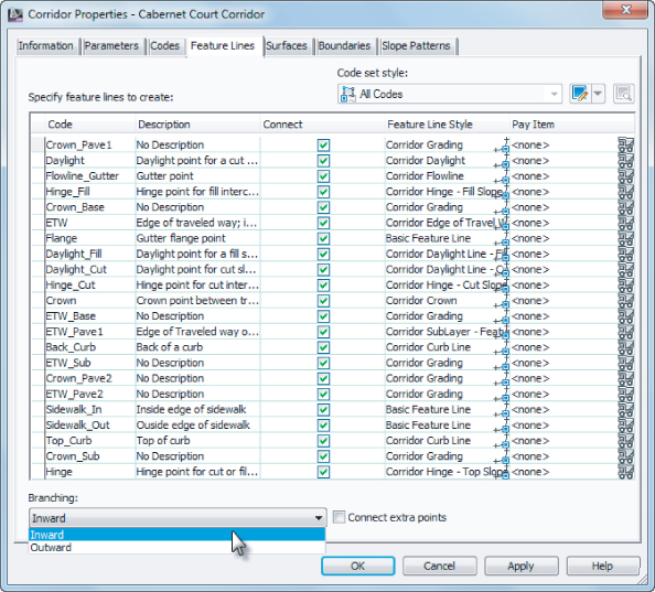
As mentioned earlier, a feature line will only connect the same point codes by default. However, the Feature Lines tab of the Corridor Properties dialog allows you to eliminate certain feature lines on the basis of the point code. For example, if for some reason you did not want your Back_Curb points connected with a feature line, you could toggle that feature line off in the Connect column.
When a corridor is built, the feature line that is created is a similar type of object to the feature line you will use in Chapter 16, “Grading,” for grading purposes. The difference is that corridor feature lines are locked in the corridor object. There is not much you can do with them until they are extracted.
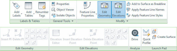
If you select the corridor to activate the contextual tab, you will notice that the Launch Pad panel, shown in Figure 10.20, offers multiple commands that relate to corridor feature lines.
Figure 10.20 Launch Pad panel of the Corridor contextual tab

Corridor feature lines can be extracted from a corridor to produce grading feature lines, alignments, profiles, and 3D polylines. A step-by-step explanation of how to extract a corridor feature line is given in the next exercise.
In the case of extracting a feature line, you have the choice of keeping the line dynamically linked to the corridor geometry or making it an entirely separate entity. If the feature line is linked, it can be used for grading and cannot be manipulated in any way other than modifying the corridor (i.e., it cannot be grip-edited). If the feature line is not linked, it can be used for grading or as a target in a corridor. The nonlinked feature line can be grip-edited and is completely divorced from the originating corridor. Both types of feature lines can be used as breaklines in surface models.
Once an alignment, profile, or 3D polyline has been extracted, its geometry can be adjusted independently. In this case, the profile, alignment, or polyline no longer retains a link to the corridor from which it originated. Once a profile, alignment, or 3D polyline has been extracted, you can use it as a target back in the corridor that formed it. In the following exercise, a corridor feature line is extracted to produce an alignment and profile:

Figure 10.21 Selecting the ETW feature line to be extracted as an alignment

- Alignment Style is set to Basic
- Alignment Label Set is set to _No Labels
- The Create Profile check box is selected
Figure 10.22 The completed Create Alignments From Objects dialog

Figure 10.23 The Create Profile – Draw New dialog
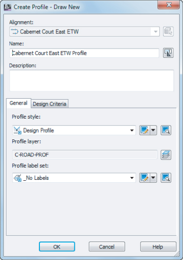
Figure 10.24 A completed alignment and profile shown on the Prospector tab of Toolspace


Figure 10.25 The Create Feature Line From Corridor dialog with the option to create a dynamic link turned on
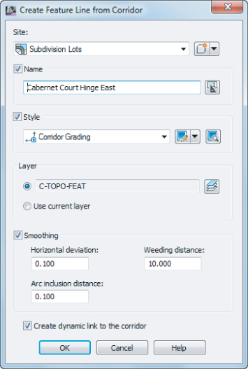
Figure 10.26 Auto Corridor Feature Line contextual tab
These alignments and feature lines can now be used for further design. Remember that feature lines created from the corridor are not connected to the corridor and will not update as you change the corridor.
When this exercise is complete, you may close the drawing. A finished copy of this drawing is available from the book's web page with the filename CorridorFeatureLine_FINISHED.dwg or CorridorFeatureLine_METRIC_FINISHED.dwg.
Understanding Targets
Every subassembly is programmed to have certain capabilities, but it needs some guidance from the user to figure out exactly how to do what is wanted. For example, a daylight subassembly contains instructions for how it is to extend to a surface model, but it is up to you to tell it which surface model to work with. Many of the lane subassemblies can be used to hook into an offset alignment and/or profile but need your help in determining which alignment and/or profile is desired.
These instructions to the subassembly are called targets. When you built the corridor in the first exercise, Civil 3D prompted you to add targets. In that case, you specified a surface target and continued. However, surface targets are just the tip of the iceberg.
Using Target Alignments and Profiles
So far, all of the corridor examples you looked at have a constant cross section. In the next section, we'll take a look at what happens when a portion of your corridor needs to transition to a wider section and then transition back to normal.
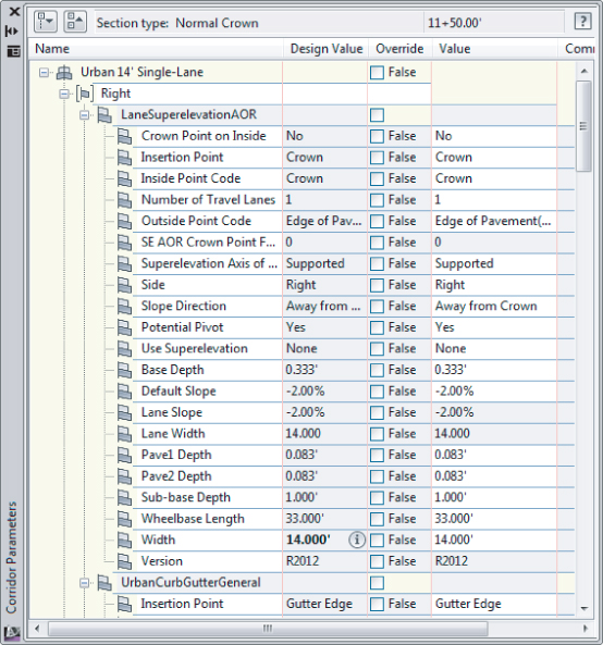
Many subassemblies have been programmed to allow for not only a baseline attachment point but also additional attachment points on target alignments and/or profiles. Be sure to check the subassembly help file to make sure the subassembly you are using will accept targets if you need them. In Chapter 8, you learned that you can right-click on any subassembly in the Tool Palettes window to enter the help file. For instance, the BasicLane subassembly will show None in the Target Parameters area of the help file, but LaneSuperElevationAOR lists Lane Width and Outside Elevation.
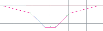
Think of a subassembly as a rubber band that is attached both to the baseline of the corridor (such as the road centerline) and the target alignment. As the target alignment, such as a lane widening, gets further from the baseline, the rubber band is stretched wider. As that target alignment transitions back toward the baseline, the rubber band changes to reflect a narrower cross section.
Figure 10.27 shows what happens to a cross section when various targets are set for the left edge of a traveled way for a lane subassembly. Figure 10.27a shows the assembly as it was originally placed in the drawing. The width from the original assembly is 14′ with a cross slope of 2 percent to the edge of pavement. Figure 10.27b shows how the geometry changes if an alignment target is set for the edge of pavement. Notice that because there is no profile specified to change the elevation, the 2 percent cross slope is held and the lane width is the only geometry that changes. Figure 10.27c shows that if both an alignment and profile are specified for an edge of pavement alignment, the design cross slope and width both change. Lastly, you see the assembly with just a profile target assigned to the edge of pavement in Figure 10.27d. In this case, the width stays at 14′ but the elevation of the edge of pavement is dictated by the profile.
Figure 10.27 How geometry changes with a target on the left: Original assembly geometry (a), assembly with width alignment target only (b), assembly with both alignment and profile target (c), and assembly with only profile target set (d).

The following exercise shows you how to set targets using alignments and profiles for a corridor lane widening:
![]()
Figure 10.28 Offset Alignment Parameters palette

![]()
Figure 10.29 The Set Width Or Offset Target dialog
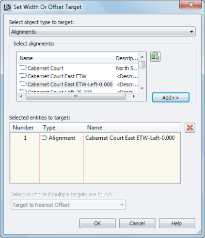
Figure 10.30 Targets set for surface and width for the right side
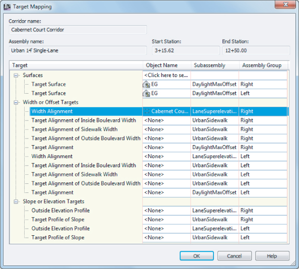
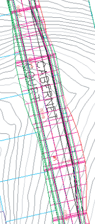
Figure 10.31 The completed exercise in plan view
You may keep this drawing open to continue on to the next exercise or use the finished copy of this drawing available from the book's web page (TargetPractice_FINISHED.dwg or TargetPractice_METRIC_FINISHED.dwg).
![]()

Editing Sections
Once your corridor is built, chances are you will want to examine it in section view, tweak a station here or there, and check for problems. For a station-by-station look at a corridor, select the corridor and from the Corridor contextual tab ⇒ Modify Corridor Sections panel, choose Section Editor (see Figure 10.32).
Figure 10.32 Some of the many tools, including the Section Editor, available on the Corridor contextual tab

Once you are in the Section Editor, you are in a purely data-driven view. That means that this is a live, editable section of the corridor and is not for plotting purposes. We will discuss plotting cross sections in Chapter 13, “Cross Sections and Mass Haul.”
The Section Editor allows for multiple viewport configurations so that you can see the plan, profile, and section all at the same time, as seen in the following exercise:
Figure 10.33 The Corridor Section Editor: Viewport Configuration dialog

Figure 10.34 The Corridor Section Editor with Viewport Configuration on

The Section Editor contextual tab offers many commands other than just Viewport Configuration, as shown in Figure 10.35.
Figure 10.35 The Corridor Section Editor contextual tab

The Station Selection panel on the Section Editor contextual tab allows you to move forward and backward through your corridor to see what each section looks like.
If you wish to edit a section, you may do so geometrically in the viewport showing the section in the Section Editor or through the Parameter Editor palette, but not both. To graphically edit a link, hold down the Ctrl key on the keyboard while selecting the item. This will activate grips that you can use to relocate or stretch the link (Figure 10.36).
Figure 10.36 A Daylight link ready for grip editing in the Section Editor

If you would rather use the Parameter Editor to make changes that are more precise to your section, do the following:
Figure 10.37 The Corridor Parameter Editor
The changes you make can be applied to just the section you are viewing or to a range of stations in the region you are working in (use the Apply To A Station Range button in the Corridor Edit Tools panel to do so).
To exit the Section Editor, click the Close button on the Close panel.

Creating a Corridor Surface
![]()
A corridor provides the raw components for surface creation. Just as you would use points and breaklines to make a surface, a corridor surface uses corridor points as point data and uses feature lines and links like breaklines.
The Corridor Surface
Civil 3D does not automatically build a corridor surface when you build a corridor. From examining subassemblies, assemblies, and the corridors you built in the previous exercises, you have probably noticed that there are many “layers” of points, links, and feature lines. Some represent the very top of the finished ground of your road design, some represent subsurface gravel or concrete thicknesses, and some represent subgrade, among other possibilities. You can choose to build a surface from any one of these layers or from all of them. Figure 10.38 shows an example of a TIN surface built from the links that are all coded Top, which would represent final finished ground.
Figure 10.38 A surface built from Top code links
When you first create a surface from a corridor, the surface is dependent on the corridor object. This means that if you change something that affects your corridor and then rebuild the corridor, the surface will also update.
![]()
A corridor surface shows up as a surface under the Surfaces branch in Prospector with a slightly modified icon that denotes it as related to the corridor.

After you create the initial corridor surface, you can create a static export of the surface by changing to the Home tab ⇒ Create Ground Data panel and choosing Surfaces ⇒ Create Surface From Corridor. A detached surface will not react to corridor changes and can be used to archive a version of your surface. To remind you that this surface is not related to a corridor, the icon in the Surfaces branch in Prospector will not show the corridor icon.
Corridor Surface Creation Fundamentals
You create corridor surfaces on the Surfaces tab in the Corridor Properties palette using the following two steps (which are examined in detail later in this section):
![]()
![]()
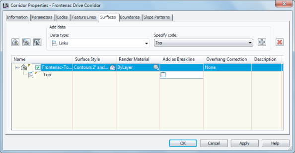
You can choose to create your corridor surface on the basis of links, feature lines, or a combination of both.
Creating a Surface from Link Data
Most of the time, you will build your corridor surface from links. As discussed earlier, each link in a subassembly is coded with a name such as Top, Pave, Datum, and so on. Choosing to build a surface from Top links will create a surface that triangulates between the points at the link vertices that represent the final finished grade.
The most commonly built link-based surfaces are Top and Datum; however, you can build a surface from any link code in your corridor. Figure 10.39 shows a schematic of how links are used to form the most common surfaces — in this case a top surface, as shown in the top image of Figure 10.39, and a datum surface, as shown in the bottom image of Figure 10.39.
Figure 10.39 Schematic of Top links connecting to form a surface (top) and schematic of Datum links connecting to form a surface (bottom)

When building a surface from links, you have the option of checking a box in the Add As Breakline column. Checking this box will add the actual link lines themselves as additional breaklines to the surface. In most cases, especially in intersection design, checking this box forces better triangulation.
Creating a Surface from Feature Lines
There might be cases where you would like to build a simple surface from your corridor — for example, by using just the crown and edge-of-travel way. If you build a surface from feature lines only or a combination of links and feature lines, you have more control over what Civil 3D uses as breaklines for the surface.
If you added all the topmost corridor feature lines to your surface item and built a surface, you would get a very similar result as if you had added the Top link codes.
Creating a Surface from Both Link Data and Feature Lines
A link-based surface can be improved by the addition of feature lines. A link-based surface does not automatically include the corridor feature lines, but instead uses the link vertex points to create triangulation. Therefore, the addition of feature lines ensures that triangulation occurs where desired along ridges and valleys. This is especially important for intersection design, curves, and other corridor surfaces where triangulation around tight corners is critical. Figure 10.40 shows the Surfaces tab of the Corridor Properties dialog where a Top link surface will be improved by the addition of Back_Curb, ETW, and Top_Curb feature lines.
Figure 10.40 The Surfaces tab indicates that the surface will be built from Top links as well as from several feature lines.
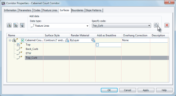
If you are having trouble with triangulation or contours not behaving as expected, experiment with adding a few feature lines to your corridor surface definition.
Create a Corridor Surface for Each Link
![]()
To the right of the Create Corridor Surface button is the Create A Corridor Surface For Each Link button. Clicking this button populates the Surface List area with a multitude of corridor surfaces; as the button name would suggest, you will now have a corridor surface for each of the link codes.
![]()
This may not be desirable for many people as you rarely need a surface for every link, but once they are created you can always remove the unwanted corridor surfaces using the Delete Surface Item button.
Corridor Surface Name Template
![]()
The third button at the upper left of the Surfaces tab of the Corridor Properties dialog is the Surface Name Template button. When you click this button, the Name Template dialog shown in Figure 10.41 appears.
Figure 10.41 The Name Template dialog for Corridor Surfaces
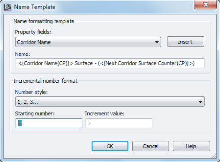
Here you can set the formatting for the corridor name as well as the number style, starting number, and increment value. The Property fields are Corridor Name and Next Corridor Surface Counter. Based on the name shown in Figure 10.41, the next surface created for the Cabernet Court corridor will be named Cabernet Court Surface – (2). The Number style can be set to 1, 2, 3 … or 01, 02, 03 … or a multitude of other styles based on the number of leading zeros.
Other Surface Tasks
You can do several other tasks on the Surfaces tab. For each corridor surface, you can set a surface style, revise the default name assigned by the Name Template, and provide a description for your corridor surface. Alternatively, you can do all those things once the corridor surface appears in the drawing through Prospector.
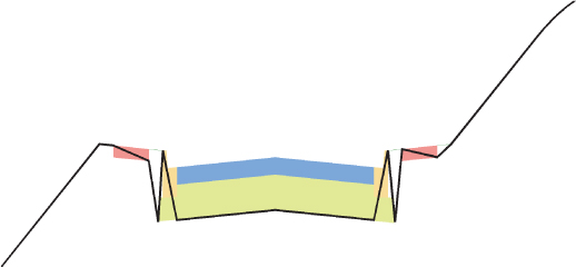
Adding a Surface Boundary
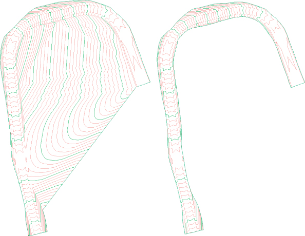
Surface boundaries are critical to any surface, but especially so for corridor surfaces. Tools that automatically and interactively add surface boundaries, using the corridor intelligence, are available. Figure 10.42 shows a corridor surface before and after the addition of a boundary. Notice how the extraneous contours have been eliminated along the line of intersection between the existing ground and the proposed ground (the daylight line), thereby creating a much more accurate surface.
Figure 10.42 A corridor surface before the addition of a boundary (left) and after the addition of a boundary (right)
You can create corridor surface boundaries using the Boundaries tab of the Corridor Properties dialog. Each corridor surface will be listed. To add the boundary, right-click on the corridor surface and select the desired boundary type.
Boundary Types
There are several tools to assist you in corridor surface boundary creation. They can be automatic, semiautomatic, or manual in nature depending on the complexity of the corridor.
You access these options on the Boundaries tab of the Corridor Properties dialog by right-clicking the name of your surface item, as shown in Figure 10.43.
Figure 10.43 Corridor Surface Boundary options for a corridor containing a single baseline

The following corridor boundary methods are listed in order of desirability. Corridor Extents As Outer Boundary is the most user-friendly, whereas Add From Polygon is fast but needs constant updating as it is not dynamically linked to the corridor.
Corridor Extents As Outer Boundary
This option is available only when you have a corridor with multiple baselines. With this selection, Civil 3D will shrink-wrap the corridor, taking into account intersections and various daylight options on different alignments. Corridor Extents As Outer Boundary will probably be your most-used boundary option.
Add Automatically
The Add Automatically boundary tool allows you to pick a point code and use the associated feature lines as your corridor boundary. This tool is available only for single-baseline corridors. Because this tool is the most automatic and easiest to apply, and will remain dynamically linked to the corridor, you will use it almost every time you build a single-baseline corridor.
Add Interactively
The Add Interactively boundary tool allows you to work your way around a corridor and choose which corridor feature lines you would like to use as part of the boundary definition.
Choosing this option is better than using Add From Polygon if Add Automatically and Corridor Extents are not available. It takes a bit of patience to trace the corridor, but the result is a dynamically linked boundary that changes if the corridor changes. Using this method, once you select a feature line, a thick line will trace around the corridor following your mouse; in order to switch to a different feature line, simply click the new feature line at the transition location. When complete, you can close the boundary just as you would a polyline.
Add From Polygon
The Add From Polygon tool allows you to choose a closed polyline (including 2D or 3D polylines) or polygon in your drawing that you would like to add as a boundary for your corridor surface. This method is quick, but unlike the other methods, the resulting boundary is not dynamic to your design.
The next exercise leads you through creating a corridor surface with an automatic boundary:
![]()
![]()
When this exercise is complete, you may close the drawing. A finished copy of this drawing is available from the book's web page with the filename CorridorBoundary_FINISHED.dwg or CorridorBoundary_METRIC_FINISHED.dwg.
Common Surface Creation Problems
Here are some common problems you may encounter when creating surfaces:
Problem
Your corridor surface does not appear or seems to be empty.
Typical Cause
You might have created the surface item but not added any data.
Fix
Open the Corridor Properties dialog and switch to the Surfaces tab. Select a data type from the drop-down menus in the Data Type and Specify Code selection boxes, and click the Add Surface Item button. Make sure your dialog shows both a surface item and a data type, as shown in Figure 10.44.
Figure 10.44 A surface cannot be created without both a surface item and a data type.
Problem
Your corridor surface does not seem to respect its boundary after a change to the assembly or surface-building data type (in other words, you switched from link data to feature lines).
Typical Cause
Automatic and interactive boundary definitions are dependent on the codes used in your corridor. If you remove or change the codes used in your corridor, the boundary needs to be redefined.
Fix
Open the Corridor Properties dialog and switch to the Boundaries tab. Remove any boundary definitions that are no longer valid (if any) by right-clicking on the boundary and selecting Remove Boundary. Once the outdated boundary has been removed, you can redefine the corridor surface boundaries using any of the applicable boundary types.
Problem
Your corridor surface seems to have gaps at points of curvature (PCs) and points of tangency (PTs) near curb returns.
Typical Cause
You may have encountered an error in rounding at these locations, and you may have inadvertently created gaps in your corridor. This is commonly the result of building a corridor using two-dimensional linework as a guide, but some segments of that linework do not touch.
Fix
Be sure your corridor region definitions produce no gaps. You might consider using the PEDIT command to join lines and curves representing corridor elements that will need to be modeled later. You might also consider setting a COGO point at these locations (PCs, PTs, and so on) and using the Node object snap instead of the Endpoint object snap to select the same location each time you are required to do so.
Performing a Volume Calculation
One of the most powerful aspects of Civil 3D is having instant feedback on your design iterations. Once you create a preliminary road corridor, you can immediately compare a corridor surface to existing ground and get a good understanding of the earthwork magnitude. When you make an adjustment to the finished grade profile and then rebuild your corridor, you can see the effect that this change has on your earthwork within minutes, if not sooner.
Even though volumes were covered in detail in Chapter 4, “Surfaces,” it is worth revisiting the subject here in the context of corridors.
This exercise uses a TIN-to-TIN composite volume calculation to compare the existing ground surface and the datum corridor surface; average end area and other section-based volume calculations are covered in Chapter 13.
![]()
![]()
Figure 10.45 Panorama showing an example of a volume surface and the cut/fill results
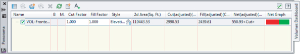
When this exercise is complete, you may close the drawing. A finished copy of this drawing is available from the book's web page with the filename CorridorVolume_FINISHED.dwg or CorridorVolume_METRIC_FINISHED.dwg.
Non-Road Corridors
As discussed in the beginning of this chapter, corridors are not just for roads. Once you have the basics about corridors down, your ingenuity can take hold.
Corridors can be used for far more than just road designs. You will explore some more advanced corridor models in Chapter 11, but there are plenty of simple, single-baseline applications for alternative corridors such as channels, berms, retaining walls, and more. You can take advantage of several specialized subassemblies or build your own custom assembly using the Subassembly Composer. Figure 10.46 shows an example of a channel corridor.
Figure 10.46 A simple channel corridor viewed in 3D built from the channel subassembly and a generic link subassembly
One of the subassemblies discussed in Chapter 8 is the channel subassembly. The following exercise shows you how to apply this subassembly to design a simple drainage channel:
Figure 10.47 The completed Drainage Channel corridor viewed in the Section Editor
When you are finished viewing the sections, dismiss the dialog by clicking the X on the Close panel. When this exercise is complete, you may close the drawing. A finished copy of this drawing is available from the book's web page with the filename CorridorChannel_FINISHED.dwg or CorridorChannel_METRIC_FINISHED.dwg.
![]()
The Bottom Line
Build a single baseline corridor from an alignment, profile, and assembly.
Corridors are created from the combination of alignments, profiles, and assemblies. Although corridors can be used to model many things, most corridors are used for road design.
Master It
Open the MasteringCorridors.dwg or MasteringCorridors_METRIC.dwg file. Build a corridor named Corridor A on the basis of the Alignment A alignment, the Project Road Finished Ground profile, and the Basic Assembly. Set all frequencies to 10′ (or 3 m for metric users).
Use targets to add lane widening.
Targets are an essential design tool used to manipulate the geometry of the road.
Master It
Open the MasteringCorridorTargets.dwg or MasteringCorridorTargets_METRIC.dwg file. Set Right Lane to target the Alignment A-Left alignment.
Create a corridor surface.
The corridor model can be used to build a surface. This corridor surface can then be analyzed and annotated to produce finished road plans.
Master It
Open the MasteringCorridorSurface.dwg or MasteringCorridorSurface_METRIC.dwg file. Create a corridor surface for the Alignment A corridor from Top links. Name the surface Corridor A-Top.
Add an automatic boundary to a corridor surface.
Surfaces can be improved with the addition of a boundary. Single-baseline corridors can take advantage of automatic boundary creation.
Master It
Open the MasteringCorridorBoundary.dwg or MasteringCorridorBoundary_METRIC.dwg file. Use the Automatic Boundary Creation tool to add a boundary using the Daylight code.