
Understanding Revit and how to use the software is not a difficult challenge. The real challenge in understanding Revit and BIM is determining how it changes your organization's culture and your project's workflow. Revit can be more than just a different way to draw a line. In this chapter, we'll focus on what those changes are and provide some tools, tips, and tricks on how to manage the changes.
In this chapter, you'll learn to:
Understand a BIM workflow
Staff a BIM project
Work in a large team
Create details in Revit
Perform quality control on your Revit model
Regardless of the workflow you have established, moving to BIM is going to be a change. In Chapter 1, "Beyond Basic Documentation," we discussed some of those changes and tried to help define your place in the process of managing that change. Regardless of where you fall on our adoption curve, you'll still need some tools to help transition from your current workflow to one using Revit. To begin, we'll cover some of the core differences between a CAD-based system and a BIM-based one.
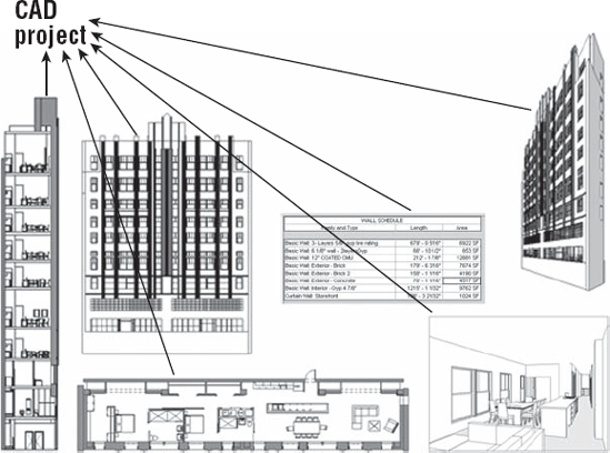
Moving to BIM is a shift in how designers and contractors look at the design and documentation process throughout the entire life cycle of the project, from concept to occupancy. In a traditional CAD-based workflow, represented in Figure 5.1, each view is drawn separately with no inherent relationship between drawings. In this type of production environment, the team creates plans, sections, elevations, schedules, and perspectives and must coordinate any changes between files manually.
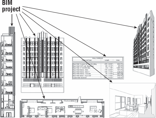
In a BIM-based workflow, the team creates a 3D, parametric model and uses this model to automatically generate the drawings necessary for documentation. Plans, sections, elevations, schedules, and perspectives are all by-products of creating an embellished a BIM model, as shown in Figure 5.2. This enhanced documentation methodology not only allows for a highly coordinated drawing set, but also provides the basic model geometry necessary for analysis such as daylighting studies, energy, material takeoffs, and so on.
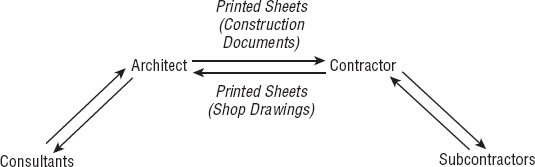
Using Revit becomes more than a change in software; it becomes a change in workflow and methodology. To better address the impacts and nuances of this change in process, let's look at the existing paradigm. A traditional or standard design and documentation workflow looks like Figure 5.3.
To describe this better, you need to understand that design is a cyclical process and one of continual refinement. As you share ideas and coordinate information with the entire project team, you can make adjustments to your own portion of the project. A standard architectural project might go something like this:
The architect draws a building design and shares this information with consultants.
Various consultants, working separately, will reuse parts of the architect's drawings to create a new series of their own drawings specific to their specialization.
The consultant's drawings will be shared with the architect who will need to use them to further coordinate their own work. Portions that affect the architectural drawings such as building structure or mechanical ductwork are in a large portion redrawn within the architectural set.
At a certain point in the project process, all of the drawings (typically in printed form only) are shared with a contractor or builder. The contractor disseminates the drawings to various subcontractors who will need to utilize their specialties to embellish the information in the original drawings.
The contractor will create new sets of drawings with added detail, but all based on the original set of documents.
With all of these separate teams making their own sets of drawings, a system of checks and balances is needed to ensure the information is communicated accurately and effectively. In our traditional model shown earlier, the subcontractors will send their drawings back to the contractor to verify the work. The contractor will create multiple copies of the drawings (based on the number of parties needed to review) and pass them to the architect. The architect will review their own set while giving the other copies to various consultants to do the same. All of these changes will be manually transcribed to one set before being sent back to the contractor to be passed back to subcontractors for further revisions and clarifications.
This entire chain of information sharing has many opportunities for a miscommunication error in manual transcription. Much of the information is redundantly reproduced as a way of error checking, which can just as easily create its own errors. If you can utilize the advantages inherent in a BIM-based method (Figure 5.4), you can eliminate many of the redundant efforts, improve communication, and focus more time on improving the design and expediting construction.

In an ideal BIM-based system, the following occurs:
The architect and consultants would work together on a single building model. This might be one model or a model consisting of interconnected parts.
After this model reaches a stage of refinement, it is passed on to the contractor and building team to further embellish with information specific to their trades and expertise.
As they construct the physical building, the BIM model can be adjusted to reflect the changes that happen in the field.
The revised model can then be shared with the owner and facilities operator. The model can contain the necessary product information about the systems installed to aid the owner's facility operator in maintaining the building. The model can also be used for future personnel moves or even building additions.
As various design specializations interact and create the building model (Figure 5.5), you can see how structure, mechanical, energy, daylight, and other factors inform design direction. You can also draw relationships between some of these elements that might not have been as obvious in a more traditionally based approach. Although some of these specialties (such as structure and mechanical) are historically separate systems, by integrating them into a single design model, you can see how they interact in relation to other systems with a building. Analysis such as daylighting can inform your building orientation and structure. Depending on your glazing, it can also affect your mechanical requirements (as solar gain). You can see some of these effects through a computational fluid dynamics (CFD) model (used to calculate airflow). Geographic information system (GIS) data will give you your relative location globally and allow you to see how much sunlight you will be receiving or what the local temperature swings will be during the course of a day. As you can see, all of these variables can easily affect building design.
As with any methodological change, you'll have success if you address all the factors. Project success happens on more than a financial or chronological level. It is also determined by a team's ability to replicate successful results. A difficult aspect of transitioning to BIM is predictability. Any system or method, even if it is inherently inefficient, is at some level successful if the system is predictable. If you can say that x effort + y time will yield z result, there is an established comfort level with that system even if it is an inefficient system. When you move to BIM, the system automatically becomes unpredictable because team members need to experience the new system to establish a comfort level with the given results. No longer does x effort + y time yield z; instead, the result is unknown.

Eventually, you reach a point of temporary diminishing returns. The amount of effort you need to put into understanding the new process feels like it has begun to exceed the value you derive from the change, and happiness plateaus or slightly declines. At a point during this plateau, you're put in a position where you need to perform a task in a given amount of time using the new technology. It might be represented by needing to get a schematic-level design sent out to a contractor or create something as simple as a stair. Regardless, the process is a foreign one and by its nature is unpredictable in time. You'll be faced with a decision to forge ahead using an unpredictable method or revert to a more familiar yet inefficient process.
Here your path can split. By regressing to your previous process, you'll enjoy an immediate increase in happiness with the familiarity and predictability of the former method, but this will only level out and never reach any greater heights than it did before you contemplated the initial change. If you stay the course with the new process, happiness will decrease (and frustration increase) as you struggle with the change. However, eventually as the new method becomes more predictable and comfortable, your happiness can achieve greater value.
Although this might be an oversimplification of a process change, the core meaning is critical. Change can be challenging. However, to realize greater goals and adapt to an ever-changing environment both professionally and globally, you will need to rethink our process in order to achieve success. Moving to BIM is acknowledging a change in workflow and process—from abstraction to virtualization (Figure 5.6). As you transition from a traditional workflow to a BIM-based one, keep in mind the change in culture. It will help you to manage expectations, time, and team members' stress levels.

As you rethink the process of design and documentation, one of the semantic changes you will need to address is staffing. A common misconception of project management when teams are first moving from CAD to BIM is that staffing the project will be the same in both workflows. This couldn't be further from the truth. When the workflow changes, staffing allocations, time to complete tasks, and percentage of work by phase are all affected as a by-product of the change of method.
To better understand how to staff your new workflow, we'll compare the two methodologies, CAD and BIM. In Figure 5.7, we have superimposed CAD and BIM workflows. The chart in the x-direction represents project phases from conceptual design through occupancy. The chart in the y-direction represents the amount of effort in each phase. This effort can also be translated into the amount of staff or person-hours put into the project by phase.
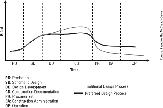
Source: Based on the McCready Curve
In a CAD-based project, the level of effort during each of the phases is fairly well known. The industry has been using some metrics over the past several years that should be fairly familiar. Typically in a CAD-based project process, effort by phase breaks down similar to what you see in Figure 5.7. The darker gray line represents a traditional or CAD-based project process. There is modest effort and staffing in conceptual design and schematic design phases, and this effort builds until it crescendoes during construction documentation. At this phase, a CAD project can greatly increase the amount of staff in an effort to expedite the completion of the drawing set. This can be effective because the CAD drawings are typically separate files and moving lines in one drawing won't dynamically change another.
The lighter gray line in Figure 5.7 represents an idealized BIM workflow. In this framework, there is still a gradual increase of staffing and effort through conceptual design and into the schematic phase, but the effort during schematic design is greater using BIM than in CAD. During SD and DD, the project team is still performing all the same tasks that occur in any design process; testing design concepts, visualizations, or design iteration. The increase in effort during the early design phases allows the team to use the parametric nature of the model to significantly reduce the effort later during construction documents, allowing for a decrease in the overall effort over the project cycle.
With such a significant change in the effort behind a BIM-based project flow, it's also important to understand how this can change the various roles and responsibilities for the project team. The changes in traditional roles can become a burden to many projects successfully adopting BIM. Project managers need to be able to predict staffing and time to complete tasks throughout the project phases and have relied on past precedent of staff and project types to do this. Since a BIM-based project can significantly alter the project workflow, many of the historic timetables for task completion are no longer valid. However, a BIM-based project can be broken down into a few primary roles that will allow you some level of predictability through the various project phases. Although the specific effort and staffing will vary between offices (and even projects), there are some general roles that will need to be accounted for on every project.
There are three primary roles on every BIM project:
- Architect
Deals with design issues, code compliances, clear widths, wall types, and so on
- Modeler
Creates content in 2D or in 3D
- Drafter
Deals with annotations, sheet layout, view creation, and detail creation
These roles represent efforts and general tasks that you need to take into account on any Revit project. On a large project, these roles could also represent individual people, whereas on a smaller project they might be all the same person or one person might carry multiple roles. We'll now cover each of these in a bit more detail and discuss how these roles interact with the project cycle.
The role of the architect is to deal with the architectural issues revolving around the project. As the model is being created, you will naturally have to solve issues like constructability and wall types; set corridor widths; deal with department areas; and deal with other issues involving either codes or the overall architectural design. This role will be the one applying standards to the project (as in wall types, keynotes, and so on) and organizing the document set. This role will need to be present on the project from the beginning to ensure consistency of the virtual building creation and isn't necessarily limited to only one person. This role also might or might not be a "designer." Although it is possible to do early design in Revit, many project teams prefer to utilize other tools such as Google SketchUp or even pencil and trace paper. The job of the architect is steering the creation of the building within Revit. Tasks for this role include the following:
Leading the creation of architectural elements and building from within the model
Designing around code requirements and other building logistics
Constructability and detailing aspects of the design
The role of the modeler is to create all the 2D and especially the 3D content needed in the project. This would include all the parametric families for things such as windows, doors, casework, wall types, stairs, railings, furnishings, and so on. Typically, this role is the responsibility of less experienced staff, who might not be able to fulfill the role or architect. These less experienced positions tend to have longer periods of undisturbed time, making them better suited to deal with some of the longer, more involved tasks in modeling content. Finally, they also tend to have some 3D experience coming out of school. They might not have worked with Revit directly, but possibly Autodesk 3ds Max or Google SketchUp, and are thereby familiar with working in a 3D environment. Tasks for this role include the following:
Creating model content and families
The role of the drafter is to create sheets and views and embellish those views with annotations or other 2D content. This role will be doing the bulk of the work needed to document the project. In earlier stages of the project, this role is typically assumed by either the architect or the modeler, but as documentation gets moving into high gear, this can quickly become the role of multiple people on a larger project. Tasks for this role include the following:
Keynoting
Dimensioning
Setting up sheets and views
Creating schedules
Now let's apply these same roles to the project timeline. It's important to understand how these various roles can be best integrated into the typical project workflow. If you look at a typical project process, outlined in Figure 5.8, you see Time on the x-axis and Effort on the y-axis. Superimposed on this chart is the light gray line shown in Figure 5.7 that represents the effort in a BIM workflow to help demonstrate staffing intensity at various times of the project cycle. We have also taken the roles of architect, modeler, and drafter and shown them in the graph represented by the numbers 1, 2, and 3, respectively.
From a staffing planning purpose, we are demonstrating the ideal times to bring in some of these various roles. At the inception of a project design, a modeling role will be of the best use. This person can help create building form, add conceptual content, and get the massing for the building established. If you're using the conceptual modeling tools (covered in Chapter 11, "Working with Consultants"), the modeler can even do some early sustainable design calculations.
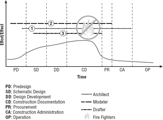
Once the project begins to take a more established form and you complete conceptual design, you'll need an architect role to step in the project. As in a typical project, you'll have to mold the form into building by applying materials, applying wall types, and validating spatial requirements and the owner's program.
During schematic design, you'll need to include the role of the drafter to begin laying out sheets and creating views. These sheets and views don't have to be for a construction document set as of yet, but you'll need to establish views for any schematic design submittals. If these views are set up properly, they can be reused later for design development and construction document submittals as the model continues to gain a greater level of detail.
What you'd like to avoid for your project staffing, if possible, is adding staff during the construction document phase. In a BIM/Revit workflow, this can sometimes cause more problems than it solves and slow down the team rather than get work done faster.

Teams in Revit will invariably structure the model in different ways to optimize individual tasks and roles on a project. Regardless, if you have one workset or several, there are a few simple tips to making sure your workflow stays fluid. In a team structure, typically you will find that certain sheets or views will inevitably become the responsibility of particular team members. Checking out an entire workset can usually cause some angst on a project team because you'll take permission over more than you need, so team members typically borrow elements from the central file. The downside of borrowing is that depending on your network environment, it can take a second or two per element to get the permissions established. This can be a real drain when you have a few hundred elements in the view you are working on. What you need is a simple way to take permission over a group of elements quickly and easily. Fortunately, Revit has a tool for that.
If you are working within a particular view, you take permission of all the elements within that view in just two clicks. By choosing the view name in the Project Browser, right-clicking on the view name, and choosing Make Workset Editable from the context menu, you'll be able to take permission over all the elements with that view. The workset discussed here isn't the workset the elements reside on but the workset of the view.
You can also take permission of all the views and their contents for an entire sheet. By right-clicking the sheet name in the Project Browser, you'll be able to take permission over all the elements in all the views on a particular sheet. Either of these methods is a quick, handy way to only take permission of the elements you can use and leave the rest available to other team members.
This shortcut was especially handy when we were recently working on a large project and had several people pulled into documentation to help meet a deadline. By allowing everyone to focus their work on specific sheets in the set, we were able to quickly take permission over just the elements and views on those sheets and get the project out the door without fear of people stepping on each other in the file.
In many projects, there is might come a time when the schedule gets tight and the project management wants to add more staff to a project to meet a specific deadline. When in a 2D CAD environment, new team members would be added to help meet a deadline and would have the burden of trying to learn the architecture of the building, the thoughts behind its design, and how its various systems interact. In a Revit project, they have that same obligation, but they have the additional task of learning how the model goes together. The model will have constraints set against various elements (such as locking a corridor width), and various digital construction issues (such as how floors and walls might be tied together or what the various family names are, or workset organization). This can take some additional time to ramp up to being viable on a project.
Regardless of planning, deadlines still escape the best of architects and project managers. It's a good idea to know when and how you can "staff up" to make sure to meet those deadlines. Keeping in mind that your team member new to the project has to learn about both the design and the model they have been thrown into, here are some easy things to have them do to both help production and make sure they don't accidentally break anything:
- Create Content, Content, Content
You will find that you will be making model families or detail components until the end of the project. This will help get the newbie engaged in a specific part of the project and also isolate them enough until they learn a bit more about how the model has gone together.
- Put Them into a Drafting Role
Even if this isn't their ultimate role, having them help create views and lay out sheets will get them familiar with the architecture while still allowing the team to keep progressing on the document set.
- Working on Detailing
Every project can always use someone who knows how to put a building together. If you have someone new to the project and possibly even new to Revit, let them embellish some of the views already created and laid out on sheets. These can be layered with 2D components, linework, and annotations.
Today, in the industry's current design workflow, we still submit 2D printed construction document sets in the majority of our work. These sets, while created from a 3D Revit model, still contain a good portion of 2D linework and embellishment (and sometimes straight-up 2D details) to get the building documented and the drawing set out the door.
When detailing within Revit, you can create and lay out three primary types of details on sheets. Knowing how and when to use each will help get your document set done, keep your model running and responsive, and minimize the amount of frustration as you adapt to a new workflow.
This type of detail is taken directly from the 3D model and used to show conditions that are otherwise difficult to visualize in a flat, 2D view. A good example of a common use for this detail type is flashing details in a brick building exterior on the interior corner of an exterior wall. Figure 5.9 shows a 3D detail in another condition at a corner balcony condition.

Note that in these types of details, it is only possible to add dimension strings that are with the same plane as the working plane. That plane can be redefined with the particular view, but the dimensions will only be able to be placed parallel to that plane. The annotations, however, will sit "flat" against the view as they would any other view.
Probably one of the most commonly created views in Revit are 2D views created directly from the model. These types of views consist of the floor plans, elevations, sections, plan details, and sectional details within the project. Figure 5.10 shows some examples.
These view types are created by taking plans, sections, or elevations from within the model and then embellishing them with two-dimensional detail components, linework, and annotations. In this way, you can add the necessary elements to the view to communicate the design and construction intent to the contractor while ensuring that when the model is updated, all the elements within the view are updated as well.

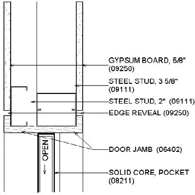
Sometimes within the drawing set it becomes necessary to draft a 2D detail. These kinds of details are drafted in a similar manner to how you'd draft the same detail using a 2D CAD system. Revit has the ability to create 2D views, and using a series of drafting commands, you can create the types of details needed for any drawing set. These detail types are typically used when you large-scale details (1½" = 1'-0" for example) as at this scale, these are elements you typically won't model. This can be used for details like doorjambs, as seen in Figure 5.11, flashing details, or similar conditions.
Revit is a single-file environment. This single file can be used individually by one person, or it can be tapped by multiple people using a feature built into Revit called worksharing. Worksharing allows more than one user to access Revit at a time, which lets a team of designers work on the same model simultaneously. The concepts and use of worksharing are covered in depth in Chapter 6, "Understanding Worksharing," so in this chapter, we'll just touch on how you would manage and plan a large project in Revit. In a large-project environment—when you have half a dozen or more people actively in the Revit file—it takes some additional coordination and planning for a successful BIM implementation.
Revit's worksharing environment can allow for multiple people within a model at the same time. Although this multiuser workflow is supported within Revit, because of the nature and workflow inherent to design, it is possible to get too many people with a model at the same time. How many is too many will vary based on the size of the model and what people are working on, but it will become obvious when the model is overburdened with team members. Save times will be slow, there will be frequent occurrences of team members asking others to Synchronize With Central (SWC) so they can acquire permission over elements, and saving work to get everyone an updated model will become a time-consuming process. As a general rule of thumb, this number seems to be about six or eight users. About this point, you'll notice a significant decrease in speed and model performance.
When this happens, it's a good idea to discuss with your project team and consultants breaking up the model into separate models that can be linked back to each other. Breaking up the model involves taking sections of the model and splitting them into distinctive parts. As an example, you might have a project that will put out a Shell and Core package followed later by an Interiors package. If the project is a large one or you're planning on more than a half dozen people working on each set, it would be wise to divide those sets into distinctive Revit files. One file would contain the Shell and Core aspects of the project. The second file would contain all the elements of the Interiors. Because the second package is going to need to show elements of the first, it's a simple matter of linking the Shell and Core Revit file into the Interiors file.
As another example, let's say you are working on a campus project so your project has multiple buildings on a site. In this case, each building can easily become a separate Revit file.
A note of caution: you can split your model apart at any time in the project process, but once it is split, it is difficult to recombine it. Trying to recombine a model will also mean that you will only be able to merge model elements. Two-dimensional information and content from one model cannot be readily combined into another.
Within this workflow, there are some things that you'll want to make sure are consistent across all the files. Here are some of these potential pitfalls and their solutions:
- You need your drawing sheets consistent between Revit files.
This can easily be addressed by either using the same template file for both projects or by exporting the Revit sheet family from one model and importing it into the other.
- Your building plans and elevations need to show the context of the other file.
This can easily be fixed by linking one file into another. This same issue can be used to solve showing the building site as well. Create the site in a third Revit file and link it in on its own workset.
- You are planning to do some renderings in Revit and need consistent materials or both models shown.
When you are working across multiple files, don't think that your building model necessarily has to be the source for all of your content. If you are creating walk-throughs or renderings, typically you are populating the view you are rendering with all kinds of entourage. You are adding people, trees, automobiles. You might also be constantly tweaking materials and lighting to get the view to render or look just right. In your production set, you don't want to see these elements popping up all over your drawings or your entourage accidentally getting printed as part of your building sections. Create a separate Revit file for this sort of production work and link your model geometry from the buildings into it. In this file, you can perform all of your renderings, add entourage, and adjust materials without the worry of interfering with the production workflow. You'll also get updates dynamically to the design every time you SWC.
- You have details that need to be consistent in multiple packages.
Any details you create within Revit can be moved from one file to another. By right-clicking the view in the Project Browser, you can use Save As to save the view and it will be saved to a separate file. This file can then be imported as a group into your other file or files and used again.
Worksets, which are part of the worksharing process, allow you to divide up portions of the model along logical building divisions. Don't think of these as layers; think of them more as building assemblies and components. Where in 2D CAD you might have doors and walls as separate layers, in Revit you might have Building Skin, Building Core, and Interior Walls as separate worksets.
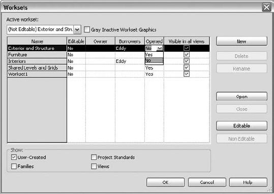
Worksets on a large project give team members a way to manage what goes into the active RAM on their individual workstations. Each workset can be selected to load or not load when you open a project. In Figure 5.12, you can see how we have chosen to open only selected worksets. To open this dialog box and change this, click the Workset button on the Manage tab.
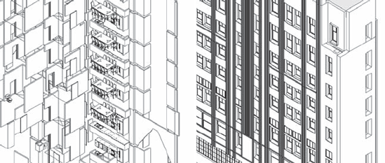
Choosing to leave a workset off means that you won't load that information into the active memory of the computer, making the model easier to manipulate and manage. It will be "lighter" and more responsive. Views will open quicker. And when you need to see your work in context with the other worksets, simply turn them back on. Figure 5.13 shows the same view with the Shell workset turned off and then turned back on. Just don't forget to turn them back on before you print your set; otherwise, you might be wondering where some of the walls have gone.
When working on a large team, one of the problems you eventually run into is trying to find families in the Project Browser or the Type Selector. As the project grows in size and more people are added, everyone seems to self-stylize their own family naming conventions. When inserting casework, you don't know if you're looking for Base-Cabinet-2 door or Cabinet-Base or Casework. Since both the family list and Type Selector sort alphabetically, it can be quite a challenge to find the family you want to insert when the list grows long.
On a recent, very large project we worked on where the architectural model alone consisted of five separate files, we needed a family-naming convention that would allow people to move back and forth between models and still be able to insert families easily. We settled on a naming convention that would utilize the first four digits of a material's MasterSpec number as the prefix to the family name. Instead of having Cast In Place Concrete in one location and Precast Concrete further down the list, the families were renamed to 0330 Cast in Place Concrete and 0345 Precast Concrete. This sorted them numerically before sorting alphabetically and allowed all the families to be located quickly. The short prefix was also useful so the description wouldn't be too truncated in the Type Selector.
In any project process, you should always maintain a level of quality control to ensure a solid workflow. When working in a BIM environment, good model maintenance is an imperative part of the process. A well-maintained model will open quickly and be responsive when changing views or manipulating content. A model that is not well maintained can have a very large file size, take a long time to open or save, or even become corrupted. Letting the quality control of your model suffer can negatively impact the team's overall production and lead to frustration because they cannot be as efficient as they'd like to be. The model size will grow, it will take a long time to save locally or SWC, and the file can suffer corruption or crashes.
Maintaining a good, healthy model is not a hard thing to accomplish. It takes about as much effort as regularly changing the oil in your car. The important thing, as with your car, is actually doing the regular maintenance so you don't have to fix a big problem that could have been avoided. In the following sections, we'll cover some simple things you can do and watch using some of the tools already built into Revit that will help flag whether there is a problem.
Watch the size of your file. The size of your file is a good metric for general file stability. A typical Revit file size for a project in construction documents will be between 100MB and 250MB—250MB is really on the high side of file sizes. Beyond that, you will find that the model will be slow to open and hard to rotate in 3D views, and other views, such as building elevations and overall plans, will also be slow to open.
Should your file become large or unwieldy, you have several ways you can trim your file down and get your model lean and responsive again.
On the Manage tab is a command called Purge Unused. This command removes all the unused families and groups from your model by deleting them. There are many times within a design process where you will change window types or wall types or swap one set of families for another. Even if those elements are not being used in the project, they are being stored within the file, and therefore when the file is opened, they are being loaded into memory. Depending on the stage of your project, you should periodically delete these elements from the model to keep your file size down. Don't worry—if you find you need a family you've removed, you can always reload it.
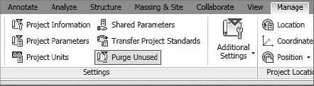
Select the Manage tab and choose Purge Unused from the Settings panel (Figure 5.14). Depending on the size of your model and how many families you have loaded, it might take Revit a few minutes to complete this command.
After Revit is done thinking, it will provide you with a list of all the families and groups in the file that are not actively within a view (Figure 5.15). At this point, you have the option to select the elements you want to delete or to keep and remove the rest.

We don't recommend that you use this command in the early stages of design. This is largely because your file size won't be that large early on, and purging at this stage would eliminate any preloaded families that you might have included in your template. During schematic design and design development, you are typically going through design iteration and will likely be adding and removing content regularly. It can become a hassle to have to constantly load or reload families into the model. If your model is not suffering from performance issues or the file size isn't unruly, it's not necessary to perform a Purge Unused.
The ability to quickly create views within a model is one of the fast and easy benefits of using Revit. This ability can also be a detriment, though, if it is not managed. Beyond the simple hassle of having to sort through many views to find the one you need, having too many views in Revit can also impact your performance and file size.
Obviously, a number of views are needed within the model to create the construction documentation. Beyond those views, you will find yourself creating additional views to study the design, deal with model creation, or simply view the building or project from a new angle. These types of "working views" will never make it to the sheet set, and some will be used for only brief periods.
How Many Working Views Is Too Many?
How many working views is too many to have in your model? The obvious answer is when performance begins to suffer, you need to start looking at ways to make the model lean and speed up response times. We had a project team new to Revit, and they were complaining about the file being slow to open and manipulate. When reviewing their model, we saw their file size was around 800MB! We were surprised they were even able to do any work at all.
One of the first things we did to get the file size down to something more reasonable was look at all the views that were not on sheets. We found they had more than 1,200 views not being used. Deleting those views paired with a File
Now, before you go through the effort of counting all your unused views to see how many you have, let's remember that Revit is a database. You can use this feature to let Revit perform the counting for you using schedules. To create a schedule that will track unused views, with the Jenkins model open, select the Schedules flyout from the View tab and choose View List (Figure 5.16).
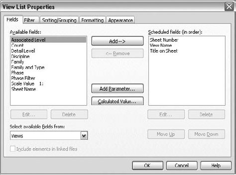
This will pull up the View List Properties dialog box (Figure 5.17) and allow you to select the fields you want to have in your schedule. For your View List schedule, select the following fields:
Sheet Number
View Name
Title on Sheet

Use the Add button to move those fields from the left column to the right one and sort them in the order listed and shown in the figure.
If you were to click OK right now, this would create a schedule of all the views you have within the model. Since you want to see only the views that are not on sheets, you have a bit more formatting to do. By selecting the next tab, Filter, you can choose to only see the views not on sheets. In the Jenkins model, there are two sheet types: those that begin with an A and ones that begin with a K.
On the Filter tab, choose to filter the sheets by Sheet Number.
Now from the drop-down menu, choose Does Not Begin With as a filter type.
Finally, in the text field, enter a capital A (see Figure 5.18).
Remember that since these are database functions, they are also case sensitive. Before moving on to the next tab, choose to add another filter selection. Copy the one you just created to filter A sheets, but now filter out all the K sheets.

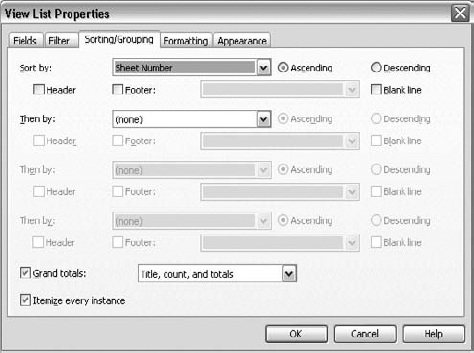
As a last bit of formatting, select the Sorting/Grouping tab. On this tab, from the drop-down menu, select Sheet Number. Should you have missed a sheet number type (for instance, if we have "G" sheets in our list), it would appear at the top. Be sure to have the Grand Totals checkbox selected and the Itemize Every Instance box selected (Figure 5.19). Click OK when you're done.
This will give you a schedule that will look similar to Figure 5.20; it shows a list and the total of all the views not on sheets in your model. You can see that in our model we have 36 views not currently on sheets. You can add this schedule to your office template where it will keep a running list of views not on sheets that you can refer to at any time in the project process.

Using schedules, as you just saw in the previous example, is a great way to use tools already in Revit to perform quality control on your model or drawings. Don't think that all schedules need to be placed on sheets. There are several uses for schedules as a quality assurance measure. In the previous example of the views, we were using schedules to help troubleshoot poor model performance; however, you can use schedules to help you QA/QC all kinds of things. In effect, schedules are used to track elements within the model, so using that logic, there are many things that would be worth tracking from a quality assurance standpoint. On larger projects, we have sometimes made a separate sheet in the drawing set and placed some of these schedules onto this sheet, allowing the project manager to have a sheet to refer to for the stewardship of the drawing set. What other kinds of quality control can you use schedules for? The following sections highlight two more examples.
Every project we've ever worked on has needed a series of wall partition types. Although Revit still lacks the ability to directly link wall partition types to both tags and schedules, the project still needs to track all the wall types used on the project.
Using the schedules, create a simply wall schedule and add Wall Type, Length, and Area to the schedule. Creating a schedule like this will give you a result something like Figure 5.21.
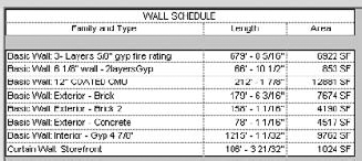
Creating a schedule like this can tell you several things. First, it will give you an up-to-date list of all the walls used in a project. If you find a wall type listed in this schedule that doesn't appear in your wall types, then you know the two have to be coordinated. Possibly you have a new wall type condition or possibly someone has used a different wall type in error.
A second use for this schedule is in pricing. This can be used to double-check contractor takeoffs for wall lengths and areas. Now remember, Revit will report actual wall areas. If you have a 10' x 10' wall, that's 100 sq. ft. of wall area. If you add a 3' x 7' door to that wall, you now will only see 79 sq. ft. of wall area in the schedule even though the length and height of the wall hasn't changed. Although this schedule won't reflect the actual amounts of materials a contractor will need to purchase to build a wall, it will reflect actual lengths and areas that can be used to cross check takeoffs.
A final use for this wall schedule is BIM-deliverable standardization. More and more clients are asking for BIM models as a deliverable in lieu of CAD files. Although standardization and naming conventions are not as robust yet as they are for 2D CAD submittals, you'll want your family-naming conventions to be easy to understand and relatively similar in style. Regularly reviewing this schedule will ensure that you are not submitting a BIM model to the client with wall names like "Susan's Wall" or "1/2" Gyp Wall"—a wall type that we recently found in one of my projects that was truly only a 1/2" wide wall.
As a final example for using schedules to manage the consistency of a project, we'll discuss how to use keynotes and textnotes in the construction document process. Regardless of whether you use keynotes (the numerical notes) or textnotes (the text-based notes), you will invariably need to use one of them to add annotations to your project. Although Revit can easily produce both types of annotation, for the sake of ease and consistency we will refer to them as keynotes for the remainder of this section because that is the name of the command within Revit.
If you are keynoting a project, you are adding annotations that call out specific materials or conditions within your details. Those notes need to not only be consistent across multiple details, but they will also link directly back to the specification—a whole separate document published outside of Revit. Historically on a project, to maintain any sort of consistency between notes in different views, you needed to manually coordinate all the notes and manually check them. When you are talking about hundreds of sheets in a drawing set and thousands of notes, there is plenty of room here for error. In a manual process, you can have notes on one sheet that read "Cast-in-Place Concrete" while on another sheet they read "CIP Concrete" and on a third sheet "Cst in Place Conncrete" (note the typos).
The Keynote tool in Revit has some built-in checks and balances to ensure a level of consistency when it is being used, and we'll go into using the keynoting tool in Chapter 19, "Annotating Your Design." However, it should be pointed out that schedules are another good way for the project manager to maintain a level of oversight across the project. A keynoting schedule will give you a running list of what notes are being used and how often a note has been inserted into a project. This list can be used to verify that all the notes read as desired (proper abbreviations are being used and the notes are free of typos) and how many times a note is being used with the project. Knowing the frequency of note use can tell you whether someone used an incorrect note; perhaps there was only one instance of a note. This overall list can also be cross-checked against the specifications so you can ensure that everything you've added to the drawings has a corresponding spec section.
To create a keynote schedule, follow these steps:
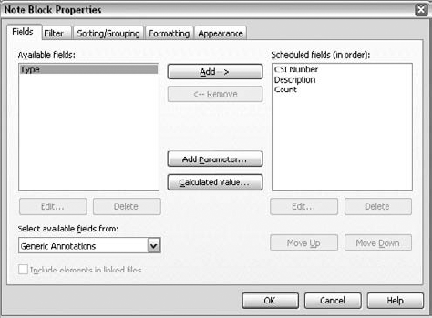
On the View ribbon, select the Schedule drop-down, and choose Note Block (Figure 5.22).
The fields for a Note Block schedule are fairly limited. From the fields list on the left, choose the following:
CSI Number
Description
Count
Then sort them in that order, as shown in Figure 5.23.
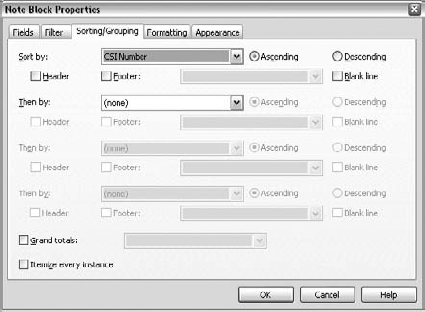
Select the Sorting/Grouping tab. From the first drop-down menu, choose CSI Number for the sort order. Make sure that both checkboxes, Grand Totals and Itemize Every Instance, are unchecked (see Figure 5.24).
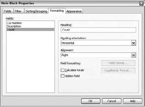
Select the Format tab and then highlight Count in the list on the left. For ease of reading the finished schedule, change the alignment of the Count field from Left to Right (Figure 5.25).

The finished schedule will look like Figure 5.26. If you look at the elements displayed in the schedule, you'll notice that it is organized by CSI division and every note will be listed so you can verify the spelling and accuracy of each item. You'll also see each time that note is used within the drawing set—GYPSUM BOARD, TYPE X 5/8" (09250)—being our most used note.
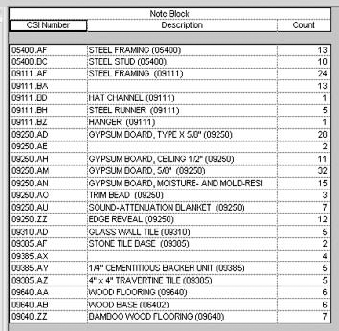
Notice that three lines are blank. These are 09111.BA, 09250.AE, and 09385.AX. In each of these conditions, we have a CSI number that has two different notes assigned to it. Since Revit cannot have multiple values in the same field within a schedule, it will show the condition as a blank. This should tell you, in this schedule, that someone has used the same number to refer to two different notes. To see which notes these are, simply highlight the line item you want to view and choose Highlight In Model in the Element panel (Figure 5.27).

Note
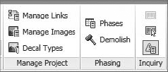
A seemingly obvious place to troubleshoot your model is the Errors And Warnings tool. Although this will do very little to affect your overall file size, the Errors And Warnings box will alert you to problems within the model that should regularly be addressed to ensure file stability. To locate this dialog box, on the Inquiry panel of the Manage tab, click the Errors And Warnings button (Figure 5.28).
Selecting this tool will give you the dialog box shown in Figure 5.29, which will list all of the errors and warnings still active in your project file.
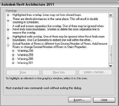
Errors and warnings are essentially all types of issues Revit has resolving geometry, conflicts, or formulas that do not equate. Things that will appear in this dialog box are instances where you have multiple elements sitting directly on top of each other, thereby creating inaccurate schedule counts; wall joints that do not properly clean themselves up; wall and room separation lines overlapping; stairs that have the wrong number of risers between floors; and so on. This dialog box basically shows you all the times the yellow warning box showed up at the bottom-right corner of the screen and you ignored it. Errors that go unchecked not only can compound to create other errors but can lead to inaccurate reporting in schedules or even file corruption. You'll want to check the Errors And Warnings dialog box regularly as part of your periodic file maintenance and try to keep the number of instances to a minimum. You might also notice that the Errors And Warnings dialog box has an Export feature. This will export your error list to an HTML file, allowing you to read it at your leisure outside the model environment (Figure 5.30). Pulling this list into a Microsoft Word or Excel document can allow you to also distribute the errors across the team for them to be resolved.
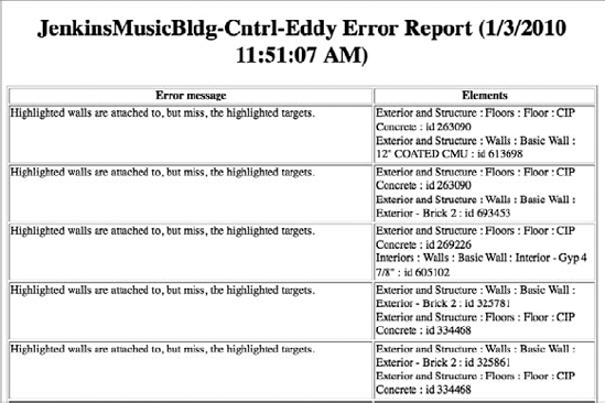
In the example shown in Figure 5.30 using the Jenkins model, we have 261 errors and warnings in the file. How many errors in a file are too many? A lot of that depends on your model, computer capabilities, what the error types are, and your deliverable. For instance, if you are delivering a BIM model to your client or to the contractor, you might have a zero error requirement. In that case, no errors are acceptable. If you still actively in the design phase of the project, however, you will always have some errors—it is an inescapable part of the process of iteration. As you refine the drawings, errors will be resolved, and as you add new content to the model that is in need of resolution, new errors will be created. If you are not worried about a model deliverable, you can get away with having fewer than 1,000 errors in the project without too much trouble. That said, the cleaner the model, the smoother it will run.
Design options are a great way to work through possible design iterations while keeping all the content within the same model. We'll discuss how to use them specifically later in this book, but also understand they are not meant to become a permanent part of the model. Having design options within your model will eventually increase your file size the longer they stay in there. Over time, you will have difficulty in removing them as elements and views will be created and associated to the various elements within a particular design option. As a general rule of thumb, you'll want to leave the design options active in your model long enough for you to make a decision on the design direction. Then, once that decision is reached, it is in your best interests to remove them.
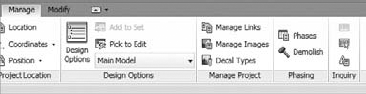
To tell if you have design options active within your model, choose the Manage tab. There is a Design Options button located on this tab (Figure 5.31).
You can also look at the status bar at the bottom of the screen for the same information (Figure 5.32).
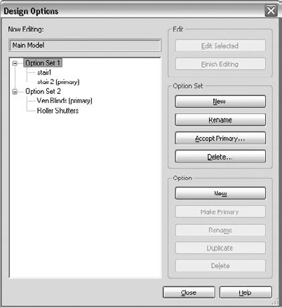
Clicking the Design Options button will pull up the Design Options dialog box shown in Figure 5.33. This dialog box will list all design options you have actively within the file. You can also delete the options here and merge the geometry back into the main model. Make sure you coordinate removing options with the rest of the project team so no work is lost.
- Understand a BIM workflow.
Understand how projects are completed in BIM and how the use of Revit on a project can change how information within a project is created.
- Master It
Explain one of the primary differences between a more traditional 2D CAD-based workflow and producing documents using Revit.
- Staff a BIM project.
Since Revit is a change in workflow, it is also important to understand the change in staffing and who is needed to perform what roles on a project.
- Master It
What are the three primary roles in a Revit project and what are the responsibilities of those roles?
- Work in a large team.
Many projects require multiple team members. Some require having a very large team assembled on a project. Working with a large team in Revit is a matter of collectively managing a series of smaller models. Know how to manage these smaller models.
- Master It
How many people is too many to have working in a single Revit file? What do you do when you reach that limit?
- Create details in Revit.
Revit is a combination of model content in 3D and annotations and embellishment in 2D to create any document set. It is important to understand when to use 3D within a model environment and what elements are best done in 2D to maintain model integrity and keep the model responsive.
- Master It
What are the three questions you should ask yourself before modeling or drafting any views in Revit?
- Perform quality control on your Revit model.
Since you have several people using one file to create possibly hundreds of drawing sheets, it's important to keep a model clean of errors and functioning well. Performing regular maintenance on your model is essential to maintaining a file stability and functionality. Should a file happen to become corrupted, you stand to lose the work of the entire team. Understand how to maintain a model and how to regularly check under the hood.
- Master It
There are several ways to keep an eye on the model so it stays responsive and free of corruption. List some of these ways.