
In this chapter, we will explore the use of Revit in the construction phase by design teams and builders. For design teams, the use of Revit usually entails markups, sketches, and revision management; however, a builder may approach BIM tools in unique ways. As of 2010, there are many different BIM programs available for builders to use in preconstruction and construction phase tasks, so we will not pretend that Revit is used by the majority of construction organizations. Instead, we will offer two case studies of companies currently using Revit for these tasks and show you some of the benefits they realize.
In this chapter, you'll learn to:
Revisions allow designers and builders to track changes made to a set of construction documents during the construction phase of a project. Since the construction documents usually consist of numerous sheets, this methodology allows everyone on the team to track and identify which changes were made and when they were made during construction. The purpose is not only to ensure correct construction but also to create as-built documentation recording how the building was actually created to be delivered to building owners upon occupancy.
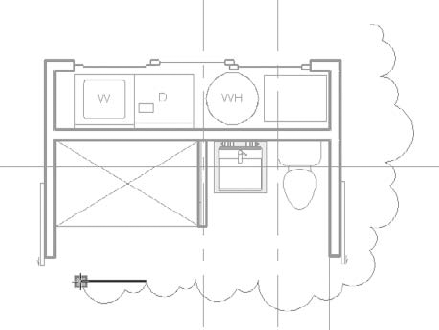
In a typical drawing set, revisions will look like Figure 21.1 when they are created in Revit and issued as part of the drawing set. Revision clouds themselves are created within views that are placed on the sheets. The Revision tag is also placed within the view, but once the view is then placed on a sheet, the revision will appear in the sheet properties and on any Revision schedule on the sheet itself.

To create a revision cloud in your project, select the Annotate tab, and choose Revision Cloud from the Detail panel (Figure 21.2). This will place you in a revisions cloud drawing mode, similar to a Sketch mode, and will allow you to bubble the revised detail or drawing. When you're finished, click the green check to complete the sketch and your annotation is done.
Typically in a project process, you won't have only one round of revisions to a document set. Revit provides controls for this and gives you the ability to name and date the various revisions in your project to better track them. The Sheet Issues/Revisions tool is located in two places in Revit. You can find it either on the View tab as the Revisions button or on the Manage tab under Additional Settings (Figure 21.3).

Either of these tools will open the Sheet Issues/Revisions dialog box (Figure 21.4). Here you can add, merge, issue, and define the behavior of revisions. Let's review the major components of this dialog box.

- Numbering
You can choose to number revisions By Sheet or By Project in Revit. This is a global setting for the whole project but can be swapped one for the other at any point. Which method you choose mainly depends on how your firm chooses to track revisions. By Sheet allows you to have as many revisions as you want within the drawing set, but on each sheet, the revision numbers always start with 1. In the example shown in Figure 21.4, the tags and revision schedule are unique for each sheet, depending on how many revisions are on each sheet with each revision on each sheet presented sequentially. This means you are chronologically numbering/tracking the changes that happened on one particular sheet, not all the changes that happened in the entire project.
Using By Project will tag your revision clouds based on the global sequence established in the project. In this example, all revisions with the same issue date would have the same revision number. So you can potentially skip a revision number on any given sheet. Either numbering method can be set in advance and added to your project template.
- Revision Table
The Sheet Issues/Revisions dialog box starts with one default revision already in place, even though you may have not made a revision yourself. This is only to give you a place to start'no revision will appear in your title blocks until you add revision clouds to your views. Each revision has a fixed number of parameters that you can enter. As you can see in Figure 21.4, the parameters include Numbering, Date, Description, and an Issued check box, in addition to Issued To and Issued By columns and options for showing clouds and tags.
- The Add Button
This function is used to create a new revision. The new revision will automatically be placed in sequential order and only the sequence number will be automatically updated. You'll need to add your own description and date.
- Revision Numbering
The Numbering option allows you to number each revision numerically, alphabetically, or not at all. If you choose alphabetic sequence, the sequence is defined in the Alphabetic Sequence options. Click the Options button in the lower right of the dialog box to set your sequence and remove letters you don't want to use. For instance, some firms don't use the letters I or O. Figure 21.5 shows a sample of the dialog box. By default, an entire alphabet will appear here. The None option will allow you to add project milestones—non-numbered entries that appear in revision tables—to sheets without having to add revision clouds.
- Revisions
To issue a revision, click the check box in the Issued column. This will lock the revision clouds placed on sheets or in views associated with that revision, preventing them from being moved, deleted, or otherwise edited. The parameter values in the dialog box will gray out and become noneditable. This is to guarantee that the clouds and data do not change downstream once you issue a set of drawings.
- Revision Clouds and Tags
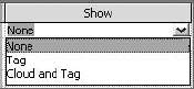
This controls the visibility of revision clouds and revision tags that have been issued. As issues occur, you may want to hide just the clouds or just the tags from previous revisions. This portion of the dialog box allows you to control individual visibility of those individual elements. For example, if you've issued a revision and then add revisions later and want to clean up your drawing, you can choose to show the issued revision as the tag only — typically a small triangle with the revision number inside it (Figure 21.6) or not show anything at all by using the None option.
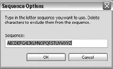

Figure 21.7 shows the options available in the Show drop-down list.
To place a revision, open a view in which changes to the model have occurred and use the Revision Cloud tool found in the Detail panel on the Annotate tab. Start drawing bubbles around the area you are calling out as a revision in a clockwise direction. Revit automatically creates a line that makes a cloud (or series of arcs), as shown in Figure 21.8. When you're finished creating the cloud, click the Finish Sketch button at the top-right side of the Ribbon.
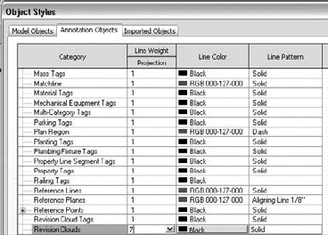
Like other objects in Revit, the graphics for revision clouds are controlled from the Object Styles dialog box (shown in Figure 21.9), accessed on the Annotation Objects tab. The default Revit setting for the line thickness is 1. We recommend that you change this to something like 7 in your project template to give it the pop you will typically see in revisions.
By default, each new revision cloud will be assigned to the last revision in the Sheet Issues/Revisions dialog box. If you need to change the revision that a cloud belongs to, select the cloud and use the Properties Palette to change it (Figure 21.10).

As soon as you have placed a revision cloud on a sheet, any revision schedules placed in your title block will update to include the revision number, description, and the date you assigned in the Sheet Issues/Revisions dialog box earlier (Figure 21.11).

Revision clouds can be tagged like many other elements in Revit. Like other tags, these are intelligent and designed to report the revision number or letter that has been assigned to the revision cloud. To place a revision tag, use the Tag By Category tool in the Tag panel on the Annotate tab.
If a tag for revisions is not in your template, you will be warned that no such tag exists in your project. To continue, simply load a revision tag. The default Revit tag loaded by default in Revit is named Revision Tag.rfa and is located in the default Annotations folder created with a standard installation.
Once you have a tag loaded, you are ready to tag revision clouds. Hover the cursor over a revision cloud and click to place the tag. You will see a preview of the tag prior to placing it (Figure 21.12). Once the tag is placed, you can drag it around the cloud to reposition it, and turn on and off the leader, and it will stay associated with the cloud.

You can choose to use a leader line between the tag and the cloud depending on your preference or your office standards. In many cases, the tag just needs to be near the cloud and a leader is not necessary. Disable the leader by selecting the tag and clearing the Leader option in the Options Bar.
The process of making supplemental drawings (SDs) entails making a change to an existing drawing and then issuing that change as a separate package during the construction process. Sometimes this can be a single 8½" x 11" or 11" x 17" sheet where the new detail is then pasted over the old one in the document set. From a workflow perspective, this can be a little disruptive in Revit for a couple of reasons:
When in Revit, placing the new detail into a smaller sheet to issue the individual drawing can lead to other problems. Since there is only one instance of the view, it requires you to take views off your Construction Document sheet and place the detail in a new sheet. The problem is the new sheet/detail is meant to replace a portion of your original document set, so your set is now out of sequence. You will need to either remove the view from the sheet it was issued on temporarily (and remember to put it back) or duplicate the view and hope that you do not need to make last-minute additional changes.
A Supplemental Drawing, once issued, is like a snapshot in time. It becomes a numbered change made to the drawing set at a given date. Because the model and all the views in the model always reflect the most current state of the project, making separate SD sheets and views within Revit will show any additional changes made to that view.
As a best practice, some architects leave all the revisions directly on the sheets where they were originally issued. The sheets can be printed to PDFs, and the PDFs (with the revision clouds) are imported into Adobe Illustrator or a similar application (where they can be properly scaled and cropped to the view or detail being revised and then placed on a template to be issued for the revision). This process not only creates a historic record of the revision, but also allows you to avoid issuing the full sheet while keeping your model up-to-date.
Autodesk Design Review offers a digital and efficient way to view and mark up 2D and 3D documents for review. This workflow is different from revisions and is geared more toward informal design review rather than the management of sheet issues. For example, if your drawings must be reviewed for quality control and overall design comments by a senior designer who might not be Revit savvy, this tool can streamline the process. The senior designer, consultant, or any other third party can make comments and review changes directly in the digital file and return them to the Revit user who needs to follow up on those reviews.
Design Review publishes files in a DWFx format. If you export the drawing sheets from Revit to DWFx, when the DWFx is linked back into Revit, Revit will automatically place the DWFx under the corresponding sheet. So there is no need on your part for any sort of alignment or placement of the revisions.
Design Review is a free tool that you can download from the Autodesk website: www.autodesk.com/designreview.
Once it's installed, you can open any DWFx or DWF file produced by any Autodesk or non-Autodesk software packages.
The DWFx format allows others to examine your design without needing to own or know how to use Revit. The files are also small, which makes them easy to email, something you cannot do with a large Revit file. There are two ways to share your model using Design Review: as 2D information or as 3D information. If you publish to 3D, you create a single 3D representation of your model. Publishing to 2D can create either a view or a whole collection of interconnected views and sheets all packaged as one file.
You can export to DWF from any view in Revit. To export your views or sheets, select the Application menu and choose Export
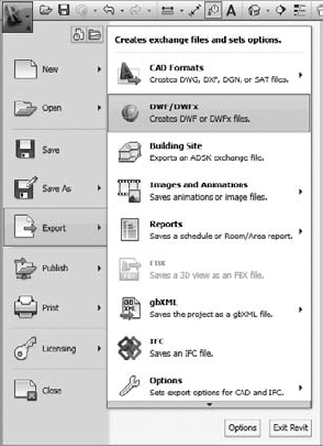
The DWF Export Settings dialog box (Figure 21.14) will open. You can choose which views/sheets to export; the default is your current view. You can choose to include or exclude any sheets or views using the Include column. When you've made your selection, click Next. By default, all your views and sheets will be combined into a single DWF file. If you want a separate file for each view and sheet, clear the option Combine Selected Views And Sheets Into Single DWF File. Let's walk through this:
Open the
Jenkins.rvtmodel on the companion web page,www.sybex.com/go/masteringrevit2011.Click the Application button, and select Export

To check the export size, open the DWF Properties tab and click the Print Setup button. In the resulting dialog box, you can set explicit sizes for your export. Click the option <Use Sheet Size> to let Revit autodetect sheet sizes based on the title blocks you are using in the project.
Click Next and specify the name of the file and a location in which to save it. Make sure you are combining all sheets into a single DWF file.

Once you have exported a DWF, you can open it in Design Review and add textual markups that can then be shared with your team and linked back into Revit. Figure 21.15 shows the exported DWF opened in Design Review.

Choose the Markup & Measure tab to begin adding comments or markups to the DWF (Figure 21.16).

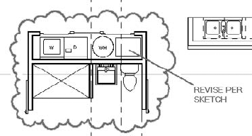
Using the shapes and draw tools on this tab, you can add clouds, arrows, and text to insert your comments or changes into the drawings. Once all your changes are created, save the file and it will retain all your changes. Figure 21.17 shows an example of a markup. While this is shown in black and white, markups can be done in a variety of colors and line weights to give them extra visibility on the page.
Once you've added markups in Design Review, save the file. You can then link the marked up DWF file back into the Revit project. On the Insert tab, choose DWF Markup (Figure 21.18).
When a DWF file is selected, Revit will link and show only the markups, not the entire DWF file. If there are no markups in the DWF file, nothing will be visible in Revit. If your file does contain markups, Revit will alert you to which sheets in the set will have comments that need to be addressed. Figure 21.19 shows a sample of the dialog box that Revit presents when inserting a marked-up DWF. In this example, there is one sheet with markups.

Note that markups can only be linked to sheets. If you export a view and mark it up, it will not show up in Revit. Always work from sheets when using Design Review for markup transfer.
You cannot move or delete linked DWF markups—they appear with a pin if selected. You can do a number of things to graphically indicate that you've dealt with a markup:
- Change its graphic appearance.
Let's say you have 20 redline markups on your sheet. You need to keep track of which ones you've picked up. One way to do this is to graphically override each markup as you make the requested modifications. Select the markup, right-click, choose View
- Hide it.
This approach is similar to the graphic override, but you hide the markup altogether. Select the markup, right-click, and choose Hide In View
- Remove it.
You can remove markups by choosing Manage Links from the Manage tab. In the Manage Links dialog box, select the DWF Markups tab, select the markup, and click the Remove button. This removes all markups associated with the link.
Now that we have reviewed some basic functionality a design team might use in the construction phase, let's take a look at how a builder (contractor, subcontractor, or construction manager) uses Revit in the industry today.
Revit is often referred to as a design application; however, contractors are using Revit more frequently as both a model authoring and project analysis tool. The increase in contractors' use of Revit parallels the increased trend of contractors adopting BIM. According to the 2009 McGraw Hill Construction SmartMarket Report The Business Value of BIM, "contractors are gaining ground faster than any other group," with 50 percent of contractors interviewed for the report using BIM in 2009, compared to 13 percent of contractors interviewed in 2007. Although contractors use Revit to obtain different results than design professionals, many of the processes and functions are the same; they are merely applied in unique ways.
A contractor might use Revit in one of several scenarios. Likely to be the most popular situation is the case in which builders will utilize Revit to construct their own virtual model of a project based on 2D drawings they receive from design teams. While this book encourages open sharing of 3D intelligent design data, the fact remains that many projects still share flattened plans, sections, and elevations for the construction phase.
Another interesting use case is that of a contractor using Revit in conjunction with architects and engineers in an integrated project delivery (IPD) environment. In this case, the perceived risks of sharing complete model data are mitigated by the IPD contractual requirements. Design, engineering, and construction teams work together to ensure the ultimate success of the project. This process requires adequate planning and development of a robust BIM execution plan.
It is important to note that construction managers may only need to support the coordination of data by other builders or provide guidance in construction phasing, staging, or cost control. Although Revit can provide much of this functionality, many other powerful tools are available in the marketplace today. Programs from Autodesk such as Navisworks Manage and others such as Vico Office Suite, Synchro Professional, Solibri Model Checker, and Beck DProfiler are developing increased interoperability with Revit. For a more complete overview on the use of these tools, please read Brad Hardin's BIM and Construction Management (Wiley Publishing, 2009).
In the following case study, contributed by Josh Lowe and Mike Whaley of J. H. Findorff & Son, Inc., you will see that Findorff finds ways to use Revit to convert 2D design data and to generate working documents for their self-performed construction tasks. It covers BIM uses in preconstruction planning and in the construction phase by a contractor implementing Revit for the sake of their own productivity. Whether you are an architect, engineer, or builder, we hope you will find this case study informative and inspirational.

Established in 1890, J. H. Findorff and Son, Inc., is a southern Wisconsin general contractor and construction management company with offices in Madison and Milwaukee. While employing an average of 600 construction professionals, they complete more than $300 million in construction annually. Findorff self-performs concrete, masonry, carpentry, steel erection, and drywall with their own teams. Their primary markets include healthcare, education (K—12), higher education (two-year and four-year), and a mixture of other commercial projects.
Using Revit for Preconstruction Planning
Using an intelligent 3D model to plan construction phase activities has several advantages over traditional approaches. Plans and uninformed spreadsheets not only take longer to produce but expose the opportunity for errors and misinterpretation. A model-based approach can support such activities as creating virtual mockups, planning for site safety, and work staging. Contractors can also use Revit in ways similar to that of an architect, as demonstrated in other chapters of this book.
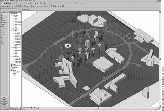
One of the very first applications of Revit for Findorff was realizing the visualization capabilities of 3D images. On a major hospital project that involved multiple tower cranes, an early Revit model was used to demonstrate to the Med-Flight helicopter team how the tower cranes would look as the helicopters approached the hospital during construction. This involved modeling the existing hospital and site as simple massing elements in one overall model with the helicopter landing pads. Combined with models of the tower cranes (including their swing zones as shown here), this model allowed multiple flight path approaches to the hospital to be simulated.
The model was then used to produce a series of animations that were presented to the hospital staff and flight crews. This mockup allowed construction to proceed with the confidence of the hospital administration, staff, Med-Flight pilots, and even field staff that the cranes and the helicopter approach would ensure the appropriate level of safety.
In another example, a Revit model of a project's major building components was linked to the project schedule in Navisworks, creating an animation, as shown here.

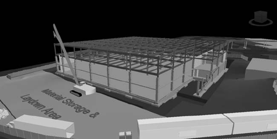
Upon review of the 4D simulation, construction team leaders realized the sequence of the construction would require that structural steel framing from the staging area be hoisted over part of the building that would was occupied. As this was an unacceptable safety condition, the construction sequence was modified, thus avoiding potential delays and unsafe conditions during actual construction.
From the very beginning, the Findorff project management staff realized the power of Revit as a site planning and utilization tool. A site utilization plan can include the basic elements of construction to determine where to place a job trailer or store materials. Families have been developed to represent typical job site elements to expedite modeling of sites, as shown here.

Beyond the placing of basic elements on the site plan, Revit is being utilized to create site models to analyze traffic and circulation patterns and sequencing for delivery of materials. In addition to site utilization, Findorff also uses Revit for schedule coordination, phasing and sequencing studies, detailed staging plans for specific field applications, and clash detection for our MEP trade partners.
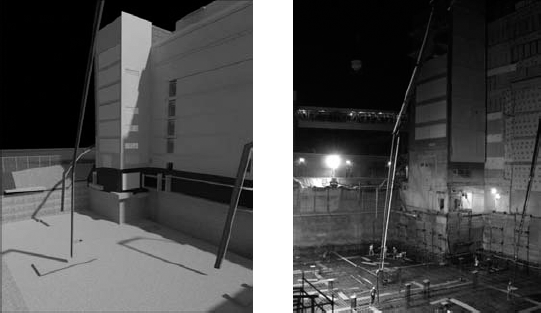
An interesting example of site phasing was a project that required a continuous concrete pour of more than 3,000 cubic yards. To further complicate this process, access to the formwork was more than 30 feet (10 m) below grade between and behind four existing buildings. To develop a productive solution to these issues, models of the concrete pump trucks with all of their characteristics for reach, swing, and setup requirements were developed. Then, using the site model and the models of the concrete pump truck, the project managers and site superintendants conducted multiple test layouts in the model, as shown here:

The model was also used to map the site access for all of the concrete trucks, including staging. The pour was completed overnight without moving the concrete pumps or adjusting any of the staging, as shown here. The Revit model is shown on the left. The right image is a photograph from the night of the pour.
Using Revit During Construction
Contractors such as Findorff are finding an increased return on their investment in training and development of BIM resources. During the construction phase, Revit can be one of many valuable tools in a builder's virtual toolbox. An example of this is using Revit models aggregated in Navisworks to allow all MEP trades to merge into the structural and architectural models for spatial coordination (shown here).
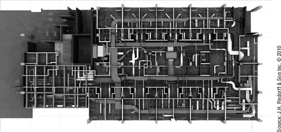
In this project, the team faced a start delay of six weeks due to a delay in getting an agency's approval. Working with all of the subcontractors, the team modeled every component above the ceilings and then agreed to a detailed sequence of installation. Many of the trades also used this as an opportunity to prefabricate many of their system components. Not only did the project recover the time lost in the agency review delay, it was completed two months ahead of schedule.
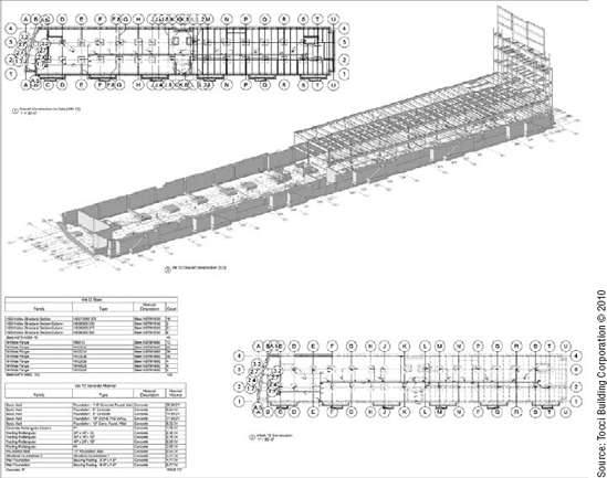
Concrete and masonry lift drawings are not new to the construction industry. Concrete superintendants and foremen have been doing lift drawings on grid paper by hand for years. Revit simply takes this process to a new level with increased efficiency and information. Findorff creates concrete lift drawings by building their own models of foundations using the architect's and engineer's drawings for reference. This allowed them to create a series of lift drawings based specifically on the exact methods of construction rather than solely on the design intent. One example of such a drawing is shown here:

Such drawings aid in the construction process by clearly identifying the work to be completed. They can contain a variety of intelligent information, including the following:
Steel embeds
Concrete openings
Architectural elements
Details
Quantities
Cost codes
Labor requirements
Advanced visualization based on accurate modeling techniques can detect potential design conflicts before they can adversely affect the on-site team. Such discrepancies are usually remedied by the modeler and reflected in the lift drawings for little or no cost. If such questions occur in the field during the installation of formwork or during a concrete pour, the cost in lost time would be substantial and probably require expensive change orders.
In addition to detecting and resolving potential conflicts in the execution of the design intent, the construction modeler will engage the project manager and superintendant to determine the optimal sequencing for each concrete pour. All major details associated with each pour are linked to the lift drawings as well as critical information, including volume of concrete, required labor, and productivity measures. These items are all generated from intelligent families of concrete objects that were created within Revit.
The use of modeling for foundations has progressed from simple foundation lift drawings to very sophisticated slab lift drawings, and the level of information and content in the lift drawings has expanded exponentially. Now lift drawings contain openings, sleeve locations, and embed information. In effect, contractors are now producing concrete field shop drawings, even modeling critical rebar areas if a conflict between rebar and formwork is anticipated. Detailed phasing models are also created using view filters to color specific parts of a model based on their construction order, as shown here:

Masonry lift drawings are a natural next step after the development of concrete lift drawings. The productivity savings from completing concrete lift drawings can be equally applied to the development of similar masonry documents. Masonry lift drawings coordinate information relating to masonry work, including but not limited to, openings, elevations, area of insulation, lintels, stone banding, sills, flashing, winter protection, block/brick counts, and manhours, as shown here.

Unlike concrete lift drawings, the breakdown on the pieces became less important and information was given based on individual elevations. The drawings then became planning tools for the field that allowed for more efficient and accurate brick ordering, crew planning, site utilization, staging/delivery management, and constant updated quantity checks throughout construction. This approach resulted in only a 1 percent variation from what was ordered to what was used.
In the following case study, contributed by Laura Handler of Tocci Building Corporation, you'll find that Tocci uses Revit in a different way from Findorff. While the previous case study focused on an implementation of what you might call lonely BIM, the following illustrates a company dedicated to the notion of social BIM. This case study examines how Tocci applies the principles of integrated design and project delivery in a collaborative environment with a project's design team.
Tocci Building Corporation (www.tocci.com) provides building and construction services throughout the Northeast and Mid-Atlantic, as well as program management and team integration throughout the United States. Through its affiliate company, Q5 LLC (www.q5thecompany.com), Tocci provides virtual design and construction (VDC) and integrated project delivery (IPD) facilitation to projects around the world. Managed by third-generation CEO (Chief Enabling Officer) John Tocci, the company began investigating and testing BIM software tools as early as 1999. By 2006, Tocci had selected the Revit suite of products for model authoring and mandated full use of VDC on all projects. Since then, Tocci has built a robust VDC team and trained all employees to utilize models on a day-to-day basis on projects.
Tocci performs work in the institutional, hospitality, and commercial markets and is nationally known as a leader in VDC and IPD. In 2009, Tocci completed the first pure IPD project on the East Coast, the Autodesk AEC Headquarters, with KlingStubbins and Autodesk, Inc.
Tocci is nationally known as a leader in virtual design and construction and has been implementing Revit for many years. They have used it in ways similar to those described in the previous case study on Findorff. Simple massing models are used to visualize major project phasing milestones, schedules and color filters facilitate preconstruction planning, and material quantities are extracted from the model to generate accurate bills of materials. One simple and innovative way Tocci utilizes the visualizations of a data-rich building information model is by placing high-resolution renderings throughout the jobsite. These images are extracted directly from the Revit project using camera views situated according to key work areas requiring clarification as shown in the following graphic. This enables subcontractors to better understand the overall design intent of a space while they execute their part of the work.

Another specific example of construction visualization is Tocci's use of phasing in Revit and some manual organization of geometry to generate visual construction phase projections'also known as a look-ahead. You can split objects such as walls and floors and then place them in specific phases, one for each week of a construction phase projection. Phase placement will drive both the data in your Revit views as well as quantity information in schedules, so it is critical that it is done carefully.
Using phase filters applied to 3D views shows where the project should be at the end of the week. The phase-filtered schedules communicate the picks of steel and volume of concrete to be poured that week (as shown here). For this project, the three-week projections were used to order materials and to communicate to subcontractors. This process helped keep the project on schedule and reduced material waste.
Planning for Integrated Project Delivery Using BIM
As described in Chapter 7, "Working with Consultants," collaboratively working in Revit requires advanced planning, often taking shape in the BIM execution plan (BEP). Although the BEP covers all BIM use on a project, Revit standards and protocols will be a large part of the BEP if a team elects to use Revit for model authoring or other BIM uses.
Although there are many BEP templates out there, including the buildingSMART Alliance's BIM Project Execution Planning Guide, Tocci Building Corporation uses an internal template that was originally developed in 2006 and has been continually refined since then. The concept of a BIM execution plan was developed in a digital charrette between Johnson & Johnson, KlingStubbins, Tocci Building Corporation, and EMCOR through the BIMForum (www.bimforum.org) to jointly streamline the BIM-enabled process. The concept was incorporated into ConsensusDOCS 301, BIM Addendum as the documentation that defines the level for which a building information model or models may be legally relied on. It has been incorporated into many other documents since then.
The BEP template and planning process described here was used by Tocci Building Corporation and KlingStubbins on the Autodesk AEC Headquarters, in Waltham, MA, the first pure IPD project on the east coast of the United States. On this project a single building information model, made up of several linked Revit files, was used during design and construction.
- Step 1: Picking the People
Before any BIM planning can be done, the BIM leads on the project must be determined. A BIM lead represents one of the BIM-enabled major project participants on the project. Start by selecting a BIM lead to represent architecture, construction, and the owner, if each party is BIM-enabled. Select BIM leads to represent other design disciplines or subcontractors as needed. BIM leads should be actual project participants, and possess technical BIM experience and a disposition toward collaboration.
- Step 2: Reviewing the Project Phases
The project phases and schedule should be reviewed, so the BIM leads can plan BIM use and standards over the course of the project. Include these in the BEP for reference.
- Step 3: Determining BIM Uses
Although a BIM can be used in a multitude of ways, each project will use a model in different ways due to the constraints of the project (schedule, complexity, needs, or team members). Determining BIM uses in the planning process will help your team focus on the most appropriate level of detail and model collaboration protocols. A list of potential BIM uses can be found on the Penn State website for BIM Project Execution Planning at
www.engr.psu.edu/ae/cic/BIMEx. This list includes information specific to each use, including potential value, resources required, and team competencies required.- Step 4: Selecting Software
Given the large number of software programs available, it is often difficult to figure out which ones are necessary. However, once you determine your BIM uses, project software selection will become clearer. The BIM leads may need to engage design consultants or subcontractors to make the final selection.
- Step 5: Establishing Standards
For each discipline, standards must be set forth for model authoring. Additionally, software-specific standards should be set for each software program needed. Because many participants will already have company-wide standards set up, compromise will be required during this step. Some of the shared standards to consider for Revit include the following:
Filenaming conventions
Component naming conventions
Material naming conventions
Workset organization
Phasing standards
Shared parameters
Units and tolerance requirements
- Step 6: Determining Model Access
With so many entities involved in Revit with an IPD project, access rights will need to be determined. For each model and person, think about the following questions:
Is live access needed or would a regular update suffice?
Does the person need to make edits to or extract information from the model?
Do they require model geometry or just parameters?
Does the participant just need to view the model?
Answering these questions helps determine if the participant should access the model live via VPN or by co-locating, versus downloading the model regularly via tools such as FTP. It will also help determine what software each person needs and if certain parts of the model should be restricted (if that is technically possible).
- Step 7: Defining the Level of Detail
One of most time-consuming parts of BIM execution planning is determining the level of detail required at each stage for each component type. This is casually referred to as "who models what, when, and how." For each object type, detail geometry definitions and parametric information required at each project stage is documented based on the project BIM uses. With walls, for example, this includes making decisions on the following:
When walls need to change from nominal to actual dimensions
When layers need to be defined
When layers need to be broken
When and how fire-rating data is input
What parameters wall tags will display
- Step 8: Mapping Workflows for Model Uses
A workflow needs to be defined and documented for each BIM use, so all parties understand the details of the use and how it fits into the overall project. Workflow is often discussed with level of detail (LOD), but it needs to be focused on and finalized. A simplified example is shown here.

In the IPD project for Autodesk's AEC Headquarters, KlingStubbins and Tocci had utilized, to the greatest extent possible, a process that supported the stewardship of data from the earliest design concepts through fabrication and installation. This process is perhaps best illustrated in the development of custom wood ceiling panels for a special customer area of the project. After a concept was conceived by the architect with input from the builder and fabricator, custom families in Revit were created to optimize the layout of the panels.

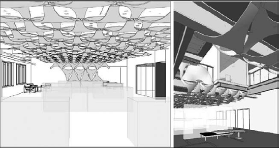
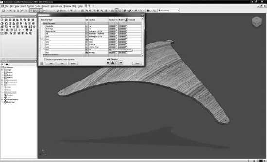
Once the panels were arranged throughout the space in the desired configuration, modelers from KlingStubbins and Tocci were able to collaborate with fabrication modelers at RB Woodcraft in Syracuse, NY, to further refine the design based on optimal constructability. Autodesk Inventor was then used to assimilate the form and generate 2D shop drawings.

When the custom panels were installed, it completed the vision of both the design and construction team while controlling cost, reducing waste, and keeping the project on schedule.

The process of using Revit for design is different than using it for conversion of 2D drawings into a construction phase model. As we have demonstrated in previous chapters of this book, generic element types and component placeholders support rapid iteration of design concepts. In contrast, a builder will likely be dealing with a design that will not change drastically throughout the construction phase. As such the builder can generate models with a higher level of detail and precision. As you will see, this approach is necessary for a builder to ensure their models are accurate and constructible. In this section we will discuss the concepts of modeling for construction and how this process may be different when working with a design team in an integrated project delivery method.
The simplest way to explain how to model like a builder is this: model it how it's going to be built. This guiding principle must be applied to accuracy, level of detail, tolerances, and technique. Here are a few examples to illustrate each of these concepts:
- Accuracy
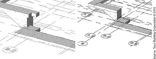
Objects need to be modeled so that they are accurate in 3D instead of merely appearing accurate in 2D plans. As shown in Figure 21.20, the foundation modeled on the left would appear correct in plan; however, the 3D geometry doesn't correctly represent the design intent. The foundation model on the right is the same condition modeled accurately. An accurate 3D model supports quantity extraction, coordination efforts, and direct-from-model total station layout.
- Level of Detail
Although the performance issues in Revit limit the level of detail that can be modeled across an entire project, it is helpful to model extreme levels of detail in specific areas—to ensure that the detail is fully coordinated in 3D, meets the design intent, and is understood by all stakeholders, enabling seamless execution of the design intent. In some cases, this means modeling blocking or pre-rock; in others it means modeling every detail of a specific assembly.
As shown in Figure 21.21, the exterior wall detail depicts flashing, backer rod, caulking, trim and finishes—among other elements created using In-Place Families. This detail was created in the architectural file for the project and placed on a specific workset named Exterior Wall Detail (its global visibility was set to not be visible in all views). The detail could also be segregated from the overall model by using a linked file or design options.
- Tolerances
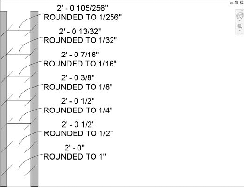
Although modeling in Revit is considered accurate, the tolerance of the modeling can be adjusted. If tolerances aren't set tight enough, issues can arise when using a model for construction. Different construction uses require different tolerances, so it is important to select the tolerances for the entire project based on the most demanding use. Revit allows for a project-wide unit tolerance as small as 1/256" or 0.001 mm, but also allows tolerances to be overridden for specific dimension styles. Rather than using dimension styles to round dimensions to appear correctly, builders require the objects to be modeled accurately. In the example shown in Figure 21.22, the impact of tolerance on modeling is demonstrated. The intended dimension between the two walls shown was 2'—1/2", but when placed, it was modeled at 2'—105/256". To make the dimension appear correctly in plan, a rounded dimension style can be used (in this case ¼" rounding would work), but if the geometry was extracted for execution (i.e., fabrication or total station layout) the as-built dimension would be closer to 2'—7/16". Although 1/16" may seem like a negligible distance, on a large project such discrepancies can accumulate to a significant length.
- Technique
It is in modeling technique that "model it how it's going to be built" takes on additional meaning. It isn't enough that the geometry is being modeled accurately; it needs to be organized based on construction methods. For instance, foundation walls and slabs are split to reflect pour sequence or the layers of walls are modeled separately to reflect construction sequence. Figure 21.23 depicts the wall-modeling workflow used by KlingStubbins and Tocci Building Corporation on the Autodesk AEC Headquarters in Waltham, MA. During concept design, walls were modeled generically. Once the floor plan was approved, KlingStubbins established wall types and Tocci Building Corporation created construction-ready walls where each layer of material was modeled as a separate wall. KlingStubbins further detailed the walls, breaking the finish to reflect reveals. Finally the geometry was used to execute the work with total station layout.


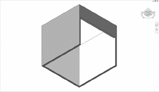
To help illustrate this method of modeling specifically for construction, this section will walk you through the process of modeling a single 10' x 10' room, including a soffit from scratch. The following process was developed to support more accurate phasing simulation and automated on-site layout by splitting the overall assembly of wall components into separate wall types. You should approach each project with careful consideration of the common goals set forth in a BIM execution plan. This level of detail may not be required in all cases.
Open the file
c21-Walls.rvtfrom this book's companion web page atwww.sybex.com/go/masteringrevit2011. Look at the basic wall types that have been created for use in the file: Core 1, Drywall PT 1, and Drywall PT 2, as shown in Figure 21.4. This assumes that the design team only defined one partition type with two different paint finishes. For an actual project, start by creating the wall types that are defined by the partition schedule and the exterior details.Select the Home tab in the ribbon and choose the Wall tool. From the Properties Palette, select the "Core 1" wall type. In the Options Bar, set Height to Unconnected: 10'-0" and Location Line to Wall Centerline.
Model the room as shown in Figure 21.24. Since the interior of the room is to be 10' x 10', model the walls 10' to 1¼" away from each other, to allow for both a layer of 5/8" drywall to be added on each side in the next step.
Activate the Wall tool again if necessary and select the wall type Drywall PT 1 from the Properties Palette. In the Options Bar, set Height to 10'—0" and the Location Line to Finish Face-Interior. Model the interior drywall layer snapping to the inside face of the Core 1 wall type you modeled in step 3. Create these segments in a counterclockwise direction; otherwise, you may need to flip the orientation of the walls using the spacebar on your keyboard.
You might find it easier to use the Pick Lines geometry method to place these wall component segments rather than drawing them from point to point. Also make sure that the Detail Level of the current view is set to Medium or Fine.
Once the drywall layer is modeled, use the Align tool to align it to the core wall and lock the constraint. Make sure that the drywall layer is locked to the core wall and not vice versa. This is accomplished with the Align tool by picking the core wall first, then the drywall layer. You may need to use the Tab key to cycle through the common faces to select the correct layers in the correct order. Be sure to watch the status bar to verify the references of the elements you are aligning.
The purpose of aligning and locking walls is so that the finish moves with the core. Try moving a core wall and notice how the finish wall moves with it. Move the wall back to its original location.
After the wall components are aligned and locked, go to the Modify tab in the ribbon and select Join from the Geometry panel. Join each finish layer to its core layer.
The purpose of joining the walls is so that doors and windows cut through all wall layers. Place a door in one of the completed walls and notice how the object cuts all the wall layers. Delete the door.
To add the drywall layers to the outside of the core layers, repeat steps 4—6 except use the wall type
Drywall PT 2, set Location Line toFinish Face-Interior, and model the walls in a clockwise direction. Repeat the process of aligning, locking, and joining the finishes to the core walls.Now, let's consider how to use this technique in a slightly more complicated situation. Select all three layers of the wall on the left side of the room and on the Properties Palette change the Base Offset to 7'-0" and the Unconnected Height to 3'-0" to create an opening as shown in Figure 21.25.
There are several methods that can be used to wrap the drywall finish around the exposed ends of the stud walls: (1) modify the profile of the finish walls or (2) model new walls. To use the latter method, create a finish wall using the same methods in steps 4—6, only changing the unconnected height to 7'-0". When joining the finish wall to the core, make sure to also join the finish wall to adjacent finish walls, as shown in Figure 21.26.
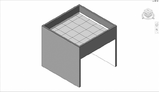
To finish the soffit assembly as shown in Figure 21.27, create a ceiling at the soffit, using ceiling type
Drywall PT 2to "cover" the exposed core wall.


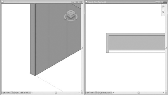
Once walls are modeled with this level of accuracy, it becomes easier to extract quantities, link the model to a phasing simulation, and export geometry to a total station for layout in the field. It also enables accurate representation of real-world construction conditions. Figure 21.28 illustrates a condition where the drywall layers are modeled only a short distance above the ceiling assembly, which is a common construction method for interior partitions.
- Add revisions to your project.
You need the ability to track changes in your design after sheets have been issued. Adding revisions to a drawing is an inevitable part of your workflow.
- Master It
Add revisions to your project that automatically get tracked on your sheet.
- Use digital markups.
DWFs provide a lightweight means to digitally transfer and mark up multiple sheets in a document set.
- Master It
Explain the workflow using DWF markups.
- Understand how a builder uses Revit.
We talked about several scenarios where builders might use Revit models during construction.
- Master It
List two ways builders use BIM and the immediate benefits of each method.