
Whether you work on large or small projects—on residential, commercial, or industrial building types—collaboration is an almost certain aspect of the workflow you will encounter when implementing BIM. This chapter will discuss important considerations for interdisciplinary coordination as well as the tools within Revit to help manage the process. While this chapter will cover aspects of collaboration solely utilizing the Revit platform, Chapter 8, "Interoperability: Working Multiplatform," will focus on collaborating with other software programs.
In this chapter, you'll learn to:
Prepare for interdisciplinary collaboration
Collaborate using linked Revit models
Use Copy/Monitor between linked models
Run interference checks
Working alone in Revit will deliver measureable increases in productivity, quality, and consistency; however, the true benefit of BIM is the ability to effectively collaborate between design disciplines with contractors and deliver useful data to facility operators.
The difference between these working paradigms has been described as lonely BIM vs. social BIM by John Tocci of Tocci Building Corporation (www.tocci.com), which is a forward-thinking construction company with headquarters in Woburn, Massachusetts. Lonely BIM can also be referred to as the use of "isolated BIM techniques for targeted tasks," whereas social BIM is the underpinning for the goals set forth by organizations such as the National Institute for Building Sciences' (NIBS) buildingSMART Alliance (according to Penn State's BIM wiki at http://bim.wikispaces.com/BIM+Project+Execution+Planning+Project). The ability to support information exchanges, such as the facility life cycle helix concept shown in Figure 7.1, necessitates the proper use of 3D models and nongraphic data in a highly collaborative environment. Furthermore, the buildingSMART Alliance and the National BIM Standard (NBIMS) stress the need for platform-neutral, open interoperability between applications, not just within a program such as Revit.

Image: Allen Edgar
Once a project team decides to participate in social BIM—either through desire or the requirements of a client—they must decide how to deliver this information in a useful way to all constituents throughout the project life cycle. Whether your client requires it or not, you should develop a BIM execution plan to define the goals, exchanges, and results related to the use of BIM.
The buildingSMART Alliance (www.buildingsmartalliance.org)—in an effort sponsored by the Charles Pankow Foundation, The Construction Industry Institute, Penn State Office of Physical Plant, and the Partnership for Achieving Construction Excellence (PACE)—has created a BIM Execution Planning Guide and template BIM Execution Guide. You can find the two guides at the Penn State Computer Integrated Construction (CIC) website: www.engr.psu.edu/ae/cic/bimex.
One of the most critical parts of a BIM execution plan is the definition of the goals and uses of BIM. If you are just beginning your implementation of Revit, perhaps you are using it because it is the latest parametric program to enter the AEC industry, or perhaps you are attempting to increase your drafting productivity. Defining clear and concise reasons for implementing BIM on each project will help you define where to concentrate your modeling efforts. According to the buildingSMART Alliance, "a current challenge and opportunity faced by the early project planning team is to identify the most appropriate uses for Building Information Modeling on a project given the project characteristics, participants' goals and capabilities, and the desired risk allocations." A listing of the common uses of BIM along with potential value opportunities and required resources is also available on the Penn State CIC website.
According to the American Institute of Architects' (AIA) "Integrated Project Delivery: A Guide," a BIM execution plan "should define the scope of BIM implementation on the project, identify the process flow for BIM tasks, define the information exchanges between parties, and describe the required project and company infrastructure needed to support the implementation." To be clear, the development of such a plan does not imply the application of integrated project delivery (IPD). IPD is "a project delivery approach that integrates people, systems, business structures and practices into a process that collaboratively harnesses the talents and insights of all participants to optimize project results, increase value to the owner, reduce waste, and maximize efficiency through all phases of design, fabrication, and construction." For the purpose of this chapter, we will consider only the collaboration and coordination between members of a project design team, not the interactions with a client or contractor.
For additional reading on IPD, refer to these sources:
IPD and BIM white papers by Ted Sive:
www.tedsive.comIntegrated Practice/Integrated Project Delivery:
www.aia.org/ipdbuildingSMART Alliance:
www.buildingsmartalliance.orgMcGraw-Hill Construction, BIM Special Section:
bim.construction.com
The coordination process within Revit will begin by linking multiple files together to form a composite view of your building project. A project can be divided in many different ways to meet a variety of workflow requirements. Most often each discipline will develop at least one separate Revit project file, many of which will be linked into each other for reference. Because there are several workflow possibilities, this chapter will focus on the coordination among a traditional design team consisting of the following:
Architect
Structural engineer
Mechanical, electrical, and plumbing engineers
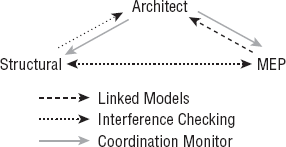
The workflow within a traditional design team is more complex than you might assume. If you were to graph the dependencies and coordination between these parties (Figure 7.2), you would see a web of primary relationships (architect to/from structure, architect to MEP) and secondary relationships (structure to/from mechanical and piping).

In addition, these relationships can be further parsed into physical and logical relationships. If we use mechanical and electrical as an example, you can see that making sure that a light fixture is not hitting the bottom of a duct is a physical relationship, while making sure that the electrical design properly accounts for the load of the heating coil in a variable air volume (VAV) box (being designed by the mechanical engineer) is a logical relationship.
It is the complexity of these possible workflow scenarios that makes this process prone to errors and a major source of coordination between the traditional design team. So, what are the tools that can be used for collaboration between Revit products? There are three distinct tools that typically are used in a collaboration scenario:
- Linked Models
Linking models together using the Revit link tool provides full visual fidelity of the referenced content, showing the complete context of the other discipline's data, fostering a complete understanding of their geometry. The data can also be controlled and shown in any manner appropriate to the use. You can turn it on or off, half-tone the data, or enhance it with color or line pattern overrides. Linking also provides support for the Interference Check and Coordination Monitor tools.
- Copy/Monitor
Copy/Monitor is a powerful tool available in all products built on the Revit platform and is considered the most intelligent of the coordination tools offering these benefits:
- Intelligent Bond
Using Copy/Monitor, you can choose items from another model that you want to monitor for change and the degree to which you want to monitor them.
- Multiple Modes
Many people do not realize that there are two distinct modes of this tool: Copy and Monitor. Using the correct mode can provide additional functionality flexibility.
- Geometry Creation
When this tool is used in Copy mode, you can create geometry in the source file based on objects in the linked file. In this mode, you will also be establishing a monitor relationship.
- Interference Check
In many cases, the only workflow requirement is to verify that items from another discipline are not interfering with your items. The Interference Check tool can be used to check between categories within a single model or between linked models.

In 2009, the Indiana University (www.iu.edu) Architect's Office announced that it would require the use of BIM on all projects with a capital value of over $5 million. Accompanying the announcement was the release of the IU BIM Standards and Project Delivery Requirements, which included a BIM execution plan template and IPD template—developed under the guidance of Autodesk and SHP Leading Design (www.shp.com/leadingdesign). Although the university's BIM requirements may seem new, the desire to ensure the maximum reuse of information has been evolving at IU for several years, beginning with its implementation of integrated GIS tools for campus and facility management in 1996.
One important excerpt from these requirements focuses on the organization of the interference checking (aka clash detection) process. Within the IU BIM Standards & Guidelines for Architects, Engineers, & Contractors, rules have been established for classifying clashes between modeled elements. Level One clashes are considered critical and include ductwork and piping clashing with ceilings, rated walls, or structure; and equipment clearances interfering with structure. Level Two clashes are less critical but include casework clashing with electrical fixtures and structure versus specialty equipment. Finally, Level Three clashes are still important but are a lower priority. These include casework clashing with walls and plumbing interfering with mechanical equipment.
These requirements may be defined differently by other clients, but it's important to understand the importance of using interference checking tools for logical groups of model elements. Checking for clashes throughout an entire model will yield a plethora of unusable data and will limit the effectiveness of model-based coordination.
For more information, visit the IU BIM site at www.indiana.edu/~uao/iubim.html or read a review of these standards at the Arch | Tech blog at www.architecture-tech.com/2009/11/indiana-university-requires-bim.html.
Given the range of available tools for collaboration in Revit, they are not necessarily applicable to all interdisciplinary relationships. As shown in Figure 7.3, only the most appropriate tools should be applied to each collaborative situation. Note that these situations are merely suggestions based on the experience of the authors. Your needs for collaborative workflows may vary.
- Architect – Structural Engineer
The relationship between the architect and structural engineer is becoming closer as we strive for lighter structures and more innovative design. In many respects, structural engineers may be affecting the building aesthetic as much as the architects. As such, this workflow may be considered the most crucial and should be bi-directional.
- Architect – Structural Engineer: Coordination Monitor
By using Copy/Monitor, the structural engineer is able to create a strong, intelligent link between the structural and architectural models. In doing so, he can easily track the changes in the architect's model that will affect the structural design. He is also able to create geometry in his model using these tools, which can be directly or indirectly related to architectural elements such as walls and floors.
Remember that coordination of relationships for datum (grids and/or levels) should be established at the beginning of a project. For example, does the architect "own" the levels and the grids—or will the structural engineer? Conflicts due to a lack of proper planning will negatively impact the effective use of the Copy/Monitor tools on your projects.
- Structural Engineer – Architect: Interference Check
The architect's primary requirement for the structural model is to include the structure in context, and to know if the structure is interfering with any architectural elements. For this workflow, it is recommended that the architect link in the structural model and use interference checking. The rules governing what clashes are considered critical may be established by a client's BIM standards and protocols.
- Architect – MEP Engineer
The relationship between architecture and MEP is not quite as dynamic as that between architecture and structure, but represents specific opportunities to benefit from collaboration.
- Architect – MEP Engineer: Coordination Monitor
The MEP engineer needs to link in the architect's model to have the architectural model for context and positional relationships for ceiling based items, and the avoidance of clashes. Copy/Monitor is used to copy and monitor the architects levels and rooms. These room objects take on the additional properties, such as light levels and airflow. Note that levels are required to copy or monitor the rooms.
- MEP Engineer – Architects: Linked Models
The architect's primary benefit from linking in the MEP model(s) is the ability to reference this geometry within the context of the architectural model and drawings. Although there is not usually a strong need to use the Coordination Monitor from MEP back to architecture, interference checking may be required under certain circumstances.
- Structural to MEP engineer(s)
This relationship is almost always best served by cross-linked models using interference checking. The most important aspect of collaboration between these disciplines is the early detection and correction of clashes.
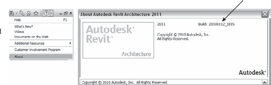
The first rule governing all Revit-to-Revit coordination situations is that all linked project files must be generated with the same platform version of Revit. For example, the architecture model must be generated with Revit Architecture 2011, the structure model must be generated with Revit Structure 2011, and the MEP model must be generated with Revit MEP 2011. In a worksharing environment, it is also important to ensure that the computers of all team members working on a project have the same build of the agreed-to Revit version installed (Figure 7.4). As discussed earlier in this chapter, a BIM execution plan should include an agreement on all modeling and coordination software to be used on a project, including the versions of each listed program.

Figure 7.4. Linked files must use the same platform version, while all worksharing team members should use the same build.
You can find the build information for your Revit product by clicking the Help drop-down button and selecting About. As shown in Figure 7.5, the build appears at the upper right of the About Autodesk Revit Architecture 2011 dialog box.
In the collaborative process of sharing information via linked models, the coordinated positioning of each model is of paramount importance. Agreement on a common coordinate system and origin must be included in every project's BIM execution plan to ensure accuracy. This section will help you develop a fundamental understanding of the coordinate systems within Revit so you can configure and manage them in your projects. For a more complete history of coordinate systems and various examples of using them within Revit, we recommend the following class material from Autodesk University 2009, available at www.au.autodesk.com:
AB118-3 Finding Your Way Around Shared Coordinates, By Teresa Martin, Ideate Inc.
AB9114-1 Autodesk Revit Collaboration: Shared Coordinates for Projects Big and Small, By Steve Stafford, AEC Advantage, Inc.
There are two coordinate systems in a Revit project: project internal and shared. Each system has essential features and limitations.
- Project Internal
Every Revit project has an internal coordinate system referred to in several places as Project. You can find this reference in the type properties of datum measuring objects such as levels and spot coordinates as well as in the settings for exporting CAD files. The project coordinate system cannot be changed and your model should be constructed within a one mile radius of the project origin. The true origin in Revit is referred to as the Project Start Up Point and the Project Base Point can be reset to this point by setting it to unclipped, right-clicking on the icon and selecting Move To Start Up Location.
A complementary component of the project internal coordinate system is the view orientation of Project North. This setting is the default and can be found in the View Properties of any plan. We strongly recommend that your model is created in an orthogonal relationship to project north or as you expect the plans to be oriented on a typical sheet. Your project's actual relation to True North will be established via shared coordinates.
- Shared Coordinates
According to Ideate's Teresa Martin, "shared coordinates are simply a way for the project team to utilize the same definitive work point." In other words, the shared coordinate system consists of a single origin and true north orientation which can be synchronized between models and even AutoCAD drawings. In the diagram shown in Figure 7.6, you will see an architectural model and structural model linked together. Each model was created using a different project base point (not the recommended method), but their shared coordinates were synchronized.

Figure 7.6. Diagram of the relationship between project base points and shared coordinates in linked models.
You can export views from Revit using the Shared setting for Coordinate System Basis; however, there are limitations when using shared coordinates for exporting. Refer to Chapter 8 for more detailed information on exporting.
When you attempt to synchronize shared coordinates between linked projects, there are two tools to achieve this: Acquire Coordinates and Publish Coordinates. A simple way to understand the difference between these tools is to think of them in terms of pulling versus pushing:
Acquire = Pull
Publish = Push
It is important to understand the situations where you would pull or push coordinates between linked files. A typical workflow for establishing a synchronized shared coordinate system on a single building project would be as follows:
A site model is generated in which the survey point in Revit is coordinated with geodetic survey markers or station lines. The site model is linked into the architectural Revit model. This file can be placed manually, then moved and rotated into a position relative to the building. Do not move or rotate your building to the linked site model!
From the Manage tab, select Coordinates, then Acquire Coordinates. Pick the linked file and the origin of the shared coordinate system and angle of true north in your Revit model will be synchronized with those in the linked file.
For all engineers or consultants using Revit, they should obtain a copy of the site model and repeat steps 1 and 2. When linking other project models that have already been synchronized with the site model, they can be placed using the Auto - By Shared Coordinates option.
Acquiring Coordinates from a CAD File
A common scenario in a project workflow begins with the architect commencing a design model and receiving a 2D survey file in DWG format from a civil engineer. The survey is drawn in coordinates that are geospatially correct but may not be orthogonal to true north. The architect should create the model close to the internal project origin; however, the architect will need to ensure the building and survey coordinates are synchronized for properly oriented CAD exports and for coordination with additional linked Revit models from engineers in later phases of the project.
The architect will link the 2D CAD file into the Revit model but will first manually place it—moving and rotating the CAD file to be in proper alignment with the building model. Once the link is in place and constrained (or locked), the architect will acquire the coordinates from the DWG survey by switching to the Manage tab and from the Project Location panel, selecting Coordinates
For a campus-style project in which you might be creating multiple instances of a linked building model, you would most likely use Publish Coordinates to push information from a site model into the linked building model. Here's how that would work in a hypothetical scenario:
Assuming a site model and building model were created in Revit, you would begin by opening the site model and linking the building model into the site.
Adjust the position of the first instance of the linked building model to location A.
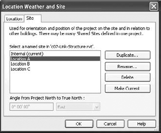
From the Manage tab in the ribbon, select Coordinates then Publish Coordinates and pick the linked model.
The Location Weather and Site dialog box will open and you will create a duplicate location named
Location Aas shown in Figure 7.7.Copy the linked building model as required for each subsequent location. Repeat steps 2–4 for each copy.
When you close the site model and open the building model, you can link the site model to the building using any of the named location references you pushed into the building model.
In prior versions of Revit, locating the project origin or shared coordinate point was only accomplished by using an imported AutoCAD file or by using spot coordinates and moving elements as required. Revit now provides two objects to identify these points: the project base point and the survey point. In the default templates, these points are visible in the floor plan named Site; however, they can also be displayed in any other plan view by opening the Visibility/Graphics Overrides dialog box, selecting the Model Categories tab and expanding the Site category as shown in Figure 7.8.
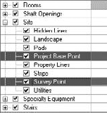
Figure 7.8. Project base point and survey point are found under Site in Visibility/Graphics Overrides.
- Project Base
Point The Project Base Point (PBP) defines the 0,0,0 point of the project. Notice that we are not calling it the origin. Using that term, you might confuse the PBP with Revit's internal project origin. The unclipped PBP can be moved in relation to the internal origin, thus creating a secondary reference point for spot coordinates, spot elevations and levels—as long as the measuring control is set to Project in the respective type properties. Moving the clipped PBP icon is the equivalent of using the Relocate Project tool, moving the project relative to the shared coordinates system.
Unless your project requires the use of a secondary point of reference other than the survey point, we recommend you do not adjust the PBP and make sure your building model lies within a close reference of this point such as the corner of a property line or intersection of column grids A and 1.
- Survey Point
The survey point is the equivalent of a station pin or geodetic survey marker in a civil engineering drawing (Figure 7.9). This is the point that will be coordinated to real geospatial coordinates. For coordination with Autodesk Civil 3D, the survey point is used when a Revit project is exported to the ADSK file format.
Note that specifying a particular location for the survey point based on civil engineering data is not a requirement. For smaller projects, the survey point and shared coordinates may never be used at all; however, these are critical in the use of analytical tools for daylighting and solar analysis.

To further expand your understanding of these points and what happens when they are modified, we have created a sample file for your reference. Open the file c07-Shared-Points.rvt from this book's companion web page (www.sybex.com/go/masteringrevit2011). In this file you will find three copies of the floor plan Level 1. Each is configured to display the project coordinates, the shared coordinates and a combination of the two. There are also two types of spot coordinates—one indicating project coordinates in which the values are prefixed with the letter p; the other indicates shared coordinates with the prefix of s. You can open these three floor plans and tile the windows (View tab, Window panel, Tile or type the keyboard shortcut WT) to get a better sense of how these points affect each other (Figure 7.10).
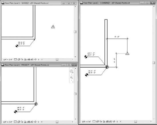
Within this sample file, you can explore the effects of moving the project base point and survey point on your model's coordinates. When selected, the project base point and survey point have paperclip icons that determine the behavior of the points when you move them. Clicking the paperclip icon changes the state from clipped to unclipped and back to clipped.
Following is a list of the possible point modifications and explanations of how they affect the project. Note that in most cases you shouldn't have to move the survey point or project base point if you are using a linked civil file (2D or 3D) and acquiring the coordinates from the linked file.
Project Base Point (PBP): Clipped
Move the PBP
PBP values change
Project-based spot coordinates don't change
Model elements 'move' relative to shared coordinates
Moving a clipped PBP is the same as using Relocate Project. That is, the model elements maintain their relationship to the PBP, but the relationship of the PBP to the survey point is changed.
Project Base Point: Unclipped
Move the PBP
PBP values change
Project-based spot coordinates change
Model doesn't move
Unclipping the PBP essentially detaches it from the internal project origin. Moving the unclipped PBP is really only used to affect the values reported in spot coordinates set to the Project origin base. It does not have any effect on exported files.
Survey Point (SP): Clipped
Move the SP
SP values don't change
Shared spot coordinates change
Model doesn't move
The clipped survey point represents the origin of the shared coordinate system. Moving it is the equivalent of setting a new origin point. Use caution if you must move the shared coordinates origin if linked models already exist in which the shared coordinates have already been synchronized. In such a case, each linked model must be opened and manually reconciled with the model in which the origin has changed.
Survey Point: Unclipped
Move the SP
SP values change
Shared spot coordinates don't change
Model doesn't move
Moving an unclipped survey point essentially doesn't do anything. It doesn't affect spot coordinates and it doesn't affect the origin of exported files.
Linked Revit models utilize what we will call a portability setting that is similar to the way XREFs are handled in AutoCAD. Although this setting is not exposed when you initially link a Revit model, you can modify the setting by switching to the Insert tab and selecting Manage Links. Change the setting in the Reference Type column as desired (Figure 7.11).
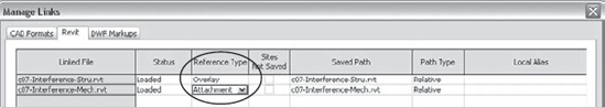
- Attachment
The Attachment option ensures that the linked model will be included if the host model is subsequently linked into other hosts. For example, if Project A is linked into Project B as an attachment, when Project B is linked into Project C, Project A will automatically be included as well.
- Overlay
The Overlay option prevents linked models from being included if the host model is subsequently linked into other hosts. For example, if Project A is linked into Project B as an overlay, when Project B is linked into Project C, Project A will not be included.
If you are utilizing linked Revit models where one or more of the project files have worksharing enabled, there are a few guidelines to follow as well as tangible benefits to be reaped. Be sure to read more about worksharing in Chapter 6, "Understanding Worksharing."
The first guideline is to ensure that the files received from consultants are set up as central files within your own domain. Even though you may not have direct access to your consultants' servers, Revit will attempt to reconcile the location of each project model's central file location. We recommend opening each received Revit file and using the following steps to set up a copy as a central file:
From the Application button, select Open

In the Open dialog box, make sure you have the worksharing-enabled project selected and check the Detach From Central option (Figure 7.12).
After the file opens, return to the Application button, and select Save or click the save icon on the Quick Access toolbar (QAT). Note that the Detach From Central option has created an unnamed project.
Save the project to a new location. When a worksharing project is detached from its central file, the first save will automatically consider the project a new central file. If you did not use the Detach From Central option when opening, you must click the Options button in the Save dialog box and choose the option Make This A Central File After Save (Figure 7.13).
Finally, click the Synchronize And Modify Settings button in the QAT and be sure to check the option to relinquish all user-created worksets before clicking OK to complete the process (Figure 7.14).
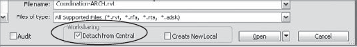

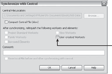
Figure 7.14. Relinquish all user-created worksets when saving a file that has been detached from central.
When the host model is enabled for worksharing, we recommend you create and reserve a workset for each linked Revit model, such as Link-RVT-Structure or Link-RVT-HVAC. This simple step will allow your team members to choose whether they would like any, all, or none of the linked models to be loaded when working on a host model. To enable this functionality, use the Specify setting in the drop-down options next to the Open button.

When the Worksets dialog box appears, select the worksets reserved for the linked models and set their Open/Closed status as you desire. The benefit of using worksets to manage linked Revit models is the flexibility it offers a project team. When a workset containing a linked model is closed, the linked model is unloaded only for that person—it does not unload for the entire team.
Additional flexibility can be leveraged through the use of the Workset parameter in both Instance and Type Properties of a linked model. In a large and complex project that consists of multiple wings where some of the wings are identical, each wing may consist of multiple linked models: architecture, structure, and MEP. Figure 7.15 shows a simplified representation of such a design where Wings A, D, and E are identical as are Wings B, C, and F.

In Figure 7.15, there are two Revit models for each discipline that represent wing design 01 and 02 (Arch01, Arch02, and so on). Note there are three instances of each linked model. For each instance of a linked model, the Workset parameter can be specified where the workset instance property represents the wing and the type property reflects either the entire discipline or one of the discipline models. For example:
Instance workset: Wing A
Type workset: Link-Architecture01 or simply, Link-Architecture
Using this example, you can choose to open the Wing A workset, which would load all the discipline models, but only for Wing A. Or, you could choose to open the Link-Architecture workset, which would load only the architectural models, but for all the wings. Note that the workset Type Properties can be modified only after a linked model has been placed in your project. Access this setting by selecting an instance of a linked model and opening the Properties Palette, and then click Edit Type. Although this functionality can offer a variety of benefits to your project team, it should be used with care and proper planning as it can adversely affect model visibility if you are using worksets for visibility manipulation.
Worksharing-enabled linked models also afford you the flexibility to adjust the visibility of project elements for the entire project, without relying on individual settings per view or maintenance of view templates. For example, grids and levels are not usually displayed from linked models because their extents are not editable in the host model and the graphics may not match those in the host model. Without worksets, the owner of the host model would have to establish visibility settings for the linked model within all views and hopefully manage those settings in view templates. Assuming the owner of the linked model maintains the levels and grids on an agreed workset such as Shared Levels and Grids, you will be able to close that workset in one place, thus affecting the entire host project. To modify the workset options for linked Revit models, follow these steps:
Open the Manage Links dialog box and switch to the Revit tab.
Select one of the linked files and click the Manage Worksets button.
In the Linking Worksets dialog box, select the worksets you would like to unload, click the Close button, and then click Reload.
Click OK to close the Manage Links dialog box.
To summarize using linked Revit models, let's review some of the benefits and limitations. You should carefully consider these aspects not only when preparing for interdisciplinary coordination, but also when managing large complex projects with linked files.
The following list highlights some of the benefits:
- Tagging Elements in Linked Files
A new feature in the Revit 2011 platform of products, most model elements (not rooms) from a linked model can be tagged in a host model. Linked views can also be utilized if the annotation exists in the linked model and needs to be displayed in the host.
- Scheduling Elements in Linked Files
In the Fields tab of the Schedule Properties dialog box, check the option Include Elements In Linked Files.
- Copying/Pasting Elements from Linked Files
In a host model, use the Tab key to select any individual element within a linked file and you can use standard copy and paste techniques to create a copy of the element in the host model.
- Hiding Elements in Linked Files
In addition to having full control of a linked model's visual fidelity through object styles, you can use the Tab key to select an individual element in a linked file and use the Hide In View commands as you would on any element within the host model.
The following list highlights some of the limitations:
- Joining Walls
Walls cannot be joined between linked Revit models. Consider alternative graphic techniques such as using coarse scale black solid fill to mask unjoined walls.
- Opening Linked Models
You cannot have a host model with loaded linked models open in the same Revit session as the linked model files. Either separate sessions of Revit must be launched or the host file must be closed before opening a linked model.
Note
Before beginning the exercises in this chapter, download the related files from this book's companion website: www.sybex.com/go/masteringrevit2011. The project files in each section's exercise should be saved because the lessons will build upon the data. In this exercise, you will do the following:
Link the architectural model to a blank project
Establish shared coordinates
Note that the structural model is essentially a blank project with a few element types specifically built for this chapter's lessons.
Open the sample project file
c07-1-Structure.rvt.Switch to the Insert tab and select Link Revit.
Navigate to the file
c07-2-Architecture.rvt.Set the Positioning option to Auto – Center To Center and click Open.
Activate the South elevation view and use the Align tool to bring the linked model's Level 1 down to align with Level 1 in the host model if necessary.
Remember, linked files should be adjusted to keep the geometry in the host model as close to the host's internal project origin as possible.
Switch to the Manage tab and from the Project Location panel, select Coordinates
Notice that the elevation value displayed in the level within the current file has changed to match the shared elevation in the linked file. This is because the Elevation Base parameter of the level's Type Properties has been set to Shared.
Save the project file for subsequent exercises in this chapter.
Once you have linked one or more Revit files into your source project file, you may want to adjust the visibility of elements within the linked files. By default, the display settings in the Visibility/Graphics dialog box are set to By Host View for linked files, which means model objects in the linked files will adopt the same appearance as the host file. In the following exercise, we'll show you how to customize these settings to turn the furniture off in the linked file and then display the room tags.
Continue this exercise with the file
c07-1-Structure.rvtwhich you saved with the linked architectural model.Activate the Level 1 floor plan from the Project Browser.
Go to the View tab in the ribbon, locate the Graphics panel, and select Visibility/Graphics. In the Visibility/Graphics dialog box, select the Revit Links tab.
You will see the linked architectural model listed as an expandable tree. Click the plus sign next to the linked file name and you will see a numbered instance of the link. This allows you to customize the visibility for each instance of a linked file if you have multiple copies of the link in the host file.
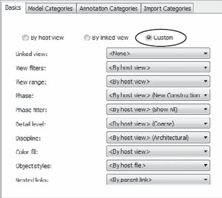
In the row displaying the linked file name, click the button in the Display Settings column which is labeled By Host View. This opens the RVT Link Display Settings dialog box.
To begin customizing the display of elements in the linked file, you must first choose the Custom option in the Basics tab as shown in Figure 7.16. This will enable all of the options in each tab of the RVT Link Display Settings dialog box.
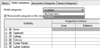
Select the Model Categories tab and choose <Custom> in the drop-down list at the top of the dialog box as shown in Figure 7.17.
Clear the checks from the following categories: Casework, Furniture and Furniture Systems.
Click OK to close all open dialog boxes.
You should observe that all the furniture and casework from the linked architecture file are no longer visible in the Level 1 floor plan. It is important to mention that in a typical architecture to structure collaboration scenario, the Structural Engineer is likely to have a view template in which typical architectural elements are already hidden. In such a case, the default By Host View settings would be sufficient. The previous exercise illustrates a scenario where additional visual control is required.
While the previous exercise focused on the display of model elements, a slightly different approach is required to utilize annotation elements from a linked file. In the following exercise, we will show you how to display the room tags from the linked architectural model. Note that many other tags can be applied to linked model elements in Revit 2011 products.
Continue with the
c07-1-Structure.rvtfile saved from the previous exercise and make sure you have activated the Level 1 floor plan.Open the Visibility/Graphics dialog box and select the Revit Links tab.
The button in the Display Settings column should be labeled as Custom based on the previous exercise. Click the Custom button to open the RVT Link Display Settings dialog box.
Select the Basics tab and click the Linked View drop-down box. You will see the floor plans available for reference in the linked file. Only view types similar to the current view in the host file will be available for use as a linked view.
Select the linked view named
Level 1-A-Anno.Click OK to close all open dialog boxes.
After completing these steps, you should see the room tags from the linked architectural file in the host file. Remember that you can tag other model elements in linked files. Try using the Tag By Category tool to place some door tags on the linked architectural model.
Once you have established the configuration of linked Revit models for your project, the next step is to create intelligently bound references between specific elements within the models. In the past, CAD users might have referenced files containing grid lines or level lines to establish some level of coordination between one user's data and another. Note that these elements in CAD are merely lines—not datum objects as they are in Revit. If these referenced elements were modified in a CAD setting, the graphic appearance of the referenced lines would update, but there would be no additional automated response to the geometry. It would be the responsibility of the recipient to update any referring geometry in their host files.
Revit's coordination tools—Copy/Monitor and Coordination Review—allow a project team to ensure a high degree of quality control while achieving it at an increased level of productivity. These tools can function on datum (levels and grids) as well as model elements such as columns, walls, and floors. The Copy/Monitor command is used first to establish the intelligent bonds between linked elements and host elements, whereas the Coordination Review command automatically monitors differences between host and linked elements which were previously bound with the Copy/Monitor command.
Although these tools are indeed powerful and have no similar discernable similarities to CAD workflows of the past, it is important to employ proper planning and coordination with your design team constituents. The familiar adage of "quality over quantity" holds true for the implementation of coordination tools in Revit. It may not be necessary to create monitored copies of all structural elements within the architectural model. How would this affect project-wide quantity takeoffs for the sake of minor improvements in graphic quality?
Again, we reiterate the necessity of developing a BIM execution plan to determine important aspects of the collaboration process. When using specific coordination tools such as those in Revit, teams might plan on issues such as these:
"Owner" of grids and levels
"Owner" of floor slabs
Are structural walls copied, monitored, or just linked?
How often are models exchanged?
How are coordination conflicts resolved?
A seemingly powerful BIM tool will not replace the need for professional supervision and the standard of care implicit to respective disciplines in the building industry. As such, there is no substitution for the most important part of effective collaboration: communication. Without open and honest communication, the coordination tools will discover conflicts, but the results may be ignored, dismissed, or overwritten to the detriment of the team's progress.
Note
The Copy/Monitor command allows you to create local copies of linked elements for better graphic control of the elements, while maintaining an intelligent bond to the linked elements. If the linked element changes in a subsequent iteration of the project file, the changes are detected in the Coordination Review tool, which will be discussed later in this chapter.
With the project file saved from the previous exercise, switch to the Collaborate tab and select Copy/Monitor

As shown in Figure 7.18, the Copy/Monitor Options dialog box in Revit Architecture is divided into five tabs representing the elements available to be copied and/or monitored. For each element tab, there is a list called Categories And Types To Copy. As shown in Figure 7.19, the Floors tab lists the available floor types in the linked model in the left column and host model floor types in the right column. Notice that any of the linked types can be specified with the option Don't Copy This Type. This can be used for quality control if your project's BIM execution plan states that certain elements are not to be copied. For example, if walls are not to be copied, switch to the Walls tab and set all linked wall types to Don't Copy This Type.
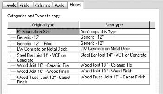
Figure 7.19. The Copy/Monitor Options dialog box allows customization for intelligent collaboration.
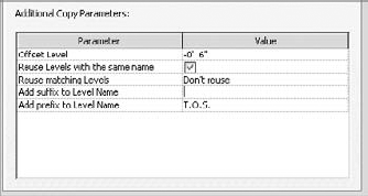
At the bottom of the Copy/Monitor Options dialog box, you will find a section called Additional Copy Parameters for each element tab (Figure 7.20). Note that the additional parameters are different for each element category. For example, when levels are copied and monitored, an offset and naming prefix can be applied to accommodate the difference between the finish floor level in a linked architectural model and the top of steel level in the host structural model.
Let's take a closer look at each of the element category options available for the Copy/Monitor tool:
- Levels
In most cases, the difference between the location of a structural level and an architectural level may lead to the presumption that you would not want to copy levels between files; however, this is a good case where you can apply additional copy parameters to build in an offset distance. Keep in mind the offset will apply to all copy/monitor selections. Thus, if a structural level needs to be offset by a different value, simply create the level in the host model and use the Monitor command to create the intelligent bond to the linked model's level. The difference will be maintained through any modifications in the linked model.
- Grids
Copying in the grids is usually a strong workflow. You can use the options on these tabs to convert the grid bubbles used by the architect into those used by the structural engineer. It is also possible to add a prefix to the grid names. For instance, you could add the value "S-" in the prefix field and then grid "A" from the architectural model will come into the structural model as "S-A."
- Columns
The structural engineer can chose to replace any column—architectural or structural—in the architectural model with an appropriate structural column; however, this implies that the architect will maintain an understanding of where differentiating column types would exist. Realistically, the structural elements should only exist in the structural engineer's model and then linked into the architectural model. The architect may then choose to either copy/monitor the linked structural columns with architectural columns (which act as finish wrappers) or to simply place architectural columns along the monitored grid lines. In the latter option, architectural columns will move along with changes in grid line locations, but would not update if structural columns are removed in the linked model.
- Walls and Floors
Similar to columns, structural walls that are important to the coordination process may be better managed in the structural model and linked into the architectural model. If you decide to use a copy/monitor relationship for these types of elements, it is best to create uniquely named wall types for structural coordination. Name such wall types in a manner that makes them display at the top of the list in the Copy/Monitor Options dialog box. You can do this by adding a hyphen (-) or underscore (_) at the beginning of the wall type name.
Finally, make sure that you select the check box Copy Windows/Doors/Openings for walls or Copy Openings/Inserts for floors so that you also get the appropriate openings for those components in the monitored elements.
Continue with the project file saved in the previous exercise in this chapter. In this exercise, you will do the following:
Use Copy/Monitor to establish new levels and grids
Use Copy/Monitor to create floors
Link the new structural model back to the architectural model
Use the Monitor option for grids in the architectural model
These steps will establish the intelligent bonds between elements in the host file with the related elements in the linked model. With the file c07-1-Structure.rvt open (saved from the previous exercise), activate the South elevation view.
Switch to the Collaborate tab and select Copy/Monitor
On the Copy/Monitor tab, click the Options button.
Select the Levels tab and enter the following options under Categories And Types To Copy:
¼" Head = TOS Head
In the Additional Copy Parameters section, set the following options:
Offset Level: −0" 6"
Add prefix to Level Name: T.O.S.
Select the Grids tab and enter the following options under Categories And Types To Copy:
¼" Bubble = ¼" Square
Select the Floors tab and enter the following options under Categories And Types To Copy:
Arch Slab 6" = LW Concrete on Metal Deck
Set all other Original Types to Do Not Copy This Type
In the Additional Copy Parameters section, set the following option:
Copy Openings/Inserts: Yes (checked)
Click OK to close the Options dialog box.
From the Copy/Monitor ribbon, choose the Copy button.
Select the Level 2 and Roof levels in the linked model. Levels in the host model should be created 6" below the linked levels with the prefix T.O.S. (Top Of Structure).
Note that there is already a Level 1 in the host model. You will need to use the Monitor tool to establish a relation to the Level 1 in the linked model.
From the Copy/Monitor ribbon, choose the Monitor button and select the Level 1 in the host model. Note that Revit will only allow you to select levels in the host model for the first pick.
Select Level 1 in the linked model to complete the monitored relationship.
Activate Section 1 and return to copy mode by clicking the Copy button in the Copy/Monitor ribbon.
Select the floor in the linked model at Level 2.
Activate the Level 1 floor plan and make sure the Copy tool is still active. Check the Multiple option in the Options Bar.
Select all the visible grids using any selection method you prefer.
Click the Finish button in the Options Bar to complete the copy process for the grids. Do not click the Finish icon in the Copy/Monitor ribbon without finishing the multiple selection mode first.
Click the Finish icon in the Copy/Monitor ribbon to exit Copy/Monitor mode.
If you now select any of the grids or levels in the host file, you will see a monitor icon near the center of the element. This indicates that the intelligent bond has been created between the host and the linked element and will evaluate any modifications in the linked file whenever the file is reloaded.
Save and close the file c07-1-Structure.rvt and then open the file c07-2-Architecture.rvt. Using the procedures you have learned earlier in this chapter, link the structural file into the architectural model. Placement should be done in the Level 1 floor plan using Auto – By Shared Coordinates positioning.
Use the Copy/Monitor tools in Monitor mode to establish the relationships of the grids between host and linked models. This will ensure that changes to grids in either model will be coordinated.
Note
After intelligent bonds have been established between elements in linked models, it is the purpose of the Coordination Review tool to support the workflow when datum or model elements are modified. This tool was designed to allow the recipient of linked data to control how and when elements in host models are modified based on changes in the linked models.
When a linked model is reloaded, which will happen automatically when the host model is opened or by manually reloading the linked model in the Manage Links dialog box, monitored elements will check for any inconsistencies. If any are found, you will see a warning message that a linked instance needs coordination review.

The coordination review warning is triggered when any of the following scenarios occur:
A monitored element in the linked model is changed, moved, or deleted.
A monitored element in the host model is changed, moved, or deleted.
Both the original monitored element and the copied element are changed, moved, or deleted.
A hosted element (door, window, opening) is added, moved, changed, or deleted in a monitored wall or floor.
The copied element in the host file is deleted.
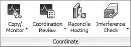
To perform a coordination review, switch to the Collaborate tab and select Coordination Review
For each of the changes detected in Coordination Review, one of the following actions can be applied. Note that actions resulting in changes to elements will only be applied to the host model; they do not modify elements in a linked model. Also note that not all options are available for all monitored elements.
- Postpone
Takes no action on the monitored element and changes the message status so that it can be filtered out or considered later.
- Reject
Select this action if you believe the change made to the element in the linked file is incorrect. A change must then be made to the element in the linked file.
- Accept Difference
Accepts the change made to the element and updates the relationship. For example, if a pair of grids was 200 mm apart, and one was moved to 300 mm away, the change would be accepted, and the relationship would now be set to 300 mm.
- Modify, Rename, Move
The command name changes based on the action. If the name of the monitored element has changed, the command reads Rename. If a column or level is moved, the command is Move. If a grid is changed or moved, the command is Modify.
- Ignore New Elements
A new hosted element has been added to a monitored wall or floor. Select this action to ignore the new element in the host. It will not be monitored for changes.
- Copy New Elements
A new hosted element has been added to a monitored wall or floor. Select this action to add the new element to the host, and monitor it for changes.
- Delete Element
A monitored element has been deleted. Select this action to delete the corresponding element in the current project.
- Copy Sketch
The sketch or boundary of a monitored opening has changed. Select this action to change the corresponding opening in the current project.
- Update Extents
The extents of a monitored element have changed. Select this action to change the corresponding element in the current project.
As you can see, Coordination Review can be a powerful tool to support the collaboration process. Remember that such a tool may not be appropriate for all elements at all times. For example, instead of copying and monitoring columns and grids, it may be sufficient to copy and monitor only grids, as the columns placed in your host model will move with the grids anyway.
In this exercise, you will utilize two files that have already been linked together with monitored elements between both files. You can download the files c07-Review-Arch.rvt (architectural model) and c07-Review-Stru.rvt (structural model) from this book's companion website: www.sybex.com/go/masteringrevit2011. In this exercise, you will do the following:
Modify elements in the architectural model
Use Coordination Review to address these changes in the structural model
Remember that you can't have a host model and a linked model open in the same session of Revit. To make this lesson easier, you can launch a second session of Revit. Open c07-Review-Arch.rvt in one session and c07-Review-Stru.rvt in the other.
In the architectural model, activate the Level 1 floor plan and make the following modifications:
Move grid line F to the north by 2"-0"
Rename grid 6 to 8
Save the architectural model and switch to the structural model. Open the Manage Links window, select the linked structural model, and click Reload. Click OK to close the dialog box.
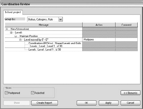
In the structural project, switch to the Collaborate tab and choose Coordination Review
When the Coordination Review dialog box opens, you will see changes to monitored elements detected in the reloaded architectural model (Figure 7.22). Note you may need to expand some of the statuses and categories to reveal the detected change and the drop-down list under the Action column.
Apply the appropriate modifying action to each of the detected changes. (Copy the sketch of the changed floor, modify the moved grid, and rename the numbered grid.)
Click Apply and OK to close the dialog box.

In the previous exercise, you might have noticed the appearance of a monitored floor sketch. Why did a floor sketch change if you only moved a grid and renamed another? The answer lies in constraints and relationships. The exterior wall in the architectural model was constrained to be 2"-0" offset from grid line F. When it was moved, the exterior wall was moved to maintain the offset. The sketches of the model's floor slabs were created using the Pick Walls tools, creating an intelligent relationship to the wall. The modified grid affected the wall, which modified the floor, and the Coordination Monitor tools ensured that all changes were detected and presented to you for action.
In addition to uses such as asset management, digital fabrication, and cost estimation, 3D coordination is one of the most important uses of building information modeling. It has an enormous potential to reduce costs of construction through the computerized resolution of clashing building elements as well as exposing opportunities for alternate trade scheduling or prefabrication. The key component to achieving 3D coordination is interference checking, also known as clash detection.
As we mentioned earlier in this chapter, not only are some building and facility owners requiring BIM processes and deliverables for new projects, they are defining how these processes are to be utilized. When you focus on interference checking, the myriad of potential clashes can be distilled into a prioritized grouping of building elements. Borrowing from Indiana University's BIM Standards & Guidelines for Architects, Engineers, & Contractors, the following is an intelligent approach to the organization of potential interferences. (Always remember that the priorities listed here are based on the requirements of one organization. The needs of your firm and those of your clients may vary.)
Level One Clashes
Clashes in these categories are considered the most critical to the coordination process. They usually relate to more costly systems or construction techniques that are more costly to delay or reschedule.
Mechanical Ductwork and Piping vs. Ceilings
Mechanical Ductwork and Piping vs. Rated Walls (for coordination of dampers and other mechanical equipment needs)
Mechanical Ductwork and Piping vs. Structure (columns, beams, framing, etc.)
All Equipment and Their Applicable Clearances vs. Walls
All Equipment and Their Applicable Clearances vs. Structure
Mechanical Equipment and Fixtures vs. Electrical Equipment and Fixtures
Mechanical Ductwork and Piping vs. Plumbing Piping
These categories of clashes are considered important to the design and construction process, but are less critical than those designated as Level One.
Casework vs. Electrical Fixtures and Devices
Furnishings vs. Electrical Fixtures and Devices
Structure vs. Specialty Equipment
Structure vs. Electrical Equipment, Fixtures, and Devices
Ductwork and Piping vs. Electrical Equipment, Fixtures, and Devices
Ductwork vs. Floors
Level Three Clashes
These clashes are considered important to the correctness of the model; however, they will usually change on a regular basis throughout the design and construction process.
Casework vs. Walls
Plumbing Piping vs. Electrical Equipment, Fixtures, and Devices
Plumbing Piping vs. Mechanical Equipment, Fixtures, and Devices
ADA Clear Space Requirements vs. Doors, Fixtures, Walls, Structure
The Interference Check tool in Revit is a basic tool supporting 3D coordination. You can use it within a single Revit project model or between linked models. You can also select elements prior to running the tool in order to detect clashes within a limited set of geometry instead of the entire project.
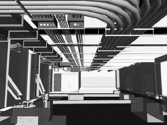
For more powerful clash detection capabilities, Autodesk offers Navisworks Manage (www.autodesk.com/navisworks), which is a multiformat model reviewing tool with various modules supporting phasing simulation, visualization, and clash detection. Figure 7.23 shows an example of a model in Navisworks Manage comprised of Revit, Tekla Structures, and AutoCAD MEP. Some of the benefits of using Navisworks for interference checking over Revit include automated views of each clash, grouping of related clashes, enhanced reporting, clash resolution tracking, and markup capabilities. Although many other 3D model formats can be opened directly in Navisworks, Revit models can be exported directly to Navisworks format with an exporter add-in.
Note
Let's take a look at the interference checking process within Revit. For this exercise, you will need to download three sample files to your computer or network: c07-Interference-Arch.rvt, c07-Interference-Mech.rvt, and c07-Interference-Stru.rvt. You can download these files from this book's companion web page: www.sybex.com/go/masteringrevit2011. The sample files are already linked into each other using relative paths, so be sure to place all three files into the same folder.
Open the file
c07-Interference-Mech.rvtand activate the 3D view named Coord-STR-MEP. You should see some ductwork in the host model and the linked structural model. The architectural model has been turned off in this view.Switch to the Collaborate tab, find the Coordinate panel, and choose Interference Check
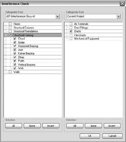
When the Interference Check dialog box appears, choose
c07-Interference-Stru.rvtfrom the Categories From drop-down list in the left column. Select Structural Framing in the left column and Ducts in the right column (Figure 7.24).The Interference Report window will appear, listing all clashes detected between the categories you selected. The list can be sorted by either Category 1 or Category 2, representing the left and right columns in the Interference Check dialog box, respectively. In Figure 7.25, one interference condition has been selected and the corresponding element is highlighted in the 3D view.

Note that you can navigate in the 3D view using any method (mouse, ViewCube, or Steering Wheel) while keeping the Interference Report open. This facilitates resolution of the clashing items. The results of the interference check can also be exported to an HTML format report. Simply click the Export button and specify a location for the report. You can now share this report with other members of your design team for remedial actions on linked models.
- Prepare for interdisciplinary collaboration.
Proper planning and communication are the foundation of effective collaboration. Although only some client organizations may require a BIM planning document, it is a recommended strategy for all design teams.
- Master It
What are the key elements of a BIM execution plan?
- Collaborate using linked Revit models.
The most basic tool for collaboration is the ability to view consultants' data directly within the context of your own model. Project files from other disciplines can be linked and displayed with predictable visual fidelity without complex conversion processes.
- Master It
How can worksharing complement the use of linked Revit models?
- Use Copy/Monitor between linked models.
The Coordination Monitor tools establish intelligent bonds between elements in a host file and correlating elements in a linked model. They also support a workflow that respects the needs of discrete teams developing their own data, perhaps on a different schedule than that of other team members.
- Master It
How can grids in two different Revit projects be related?
- Run interference checks.
Interference checking—also known as clash detection—is one of the most important uses of building information modeling. It is the essence of virtual construction and has the greatest potential for cost savings during the physical construction process.
- Master It
How do you find interfering objects between two linked Revit models?