
In the previous chapter, we discussed working with others in a Revit-to-Revit environment; however, often you'll need to work with data from other software platforms. For example, you may need to coordinate data from other disciplines, reuse legacy data, or integrate disparate design platforms. Fortunately, there are several ways to use external data within your Revit model in both 2D and 3D. We will discuss not only the methods of importing and exporting data but also when to use each method and the reasons for using specific settings. In this chapter, you'll learn to:
Use imported 2D CAD data
Export 2D CAD data
Use imported 3D model data
Export 3D model data
Work with IFC imports and exports
Based on a 2004 study, the National Institute of Standards and Technology (NIST) reported annual losses of $15.8 billion in the building industry due to insufficient interoperability. This underscores a problem that building information modeling as a whole is designed to address. Adequate interoperability will help rectify the problem illustrated in Figure 8.1, sometimes known as the BIM curve.
In Figure 8.1, the downward spikes in the lower line at the end of each project phase represent a loss of knowledge and acquired data. This usually occurs when a project is exported from BIM to a 2D CAD format or is printed to paper. Project data is then gradually reconstructed in another software platform. The upper line represents a more ideal paradigm where data and knowledge are gradually increased throughout the life of the project—a paradigm supported by BIM and full interoperability.
While full interoperability between BIM platforms is the ideal scenario, we realize that you are likely to be working with constituents who are using 2D CAD software or non-BIM 3D modelers. This chapter will show you not only how to export data and to use imported data in a variety of ways but also when and why to apply different settings to ensure the best results.
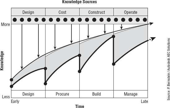
Source: P. Bernstein / Autodesk AEC Solutions
Although Revit provides ample means to generate 2D documentation based on a rich multidimensional (3D, 4D, 5D, and so on) model, there are a few real-world scenarios in which CAD data must be integrated with the building information model. Such scenarios might include the following:
Using CAD details developed within your firm
Coordinating with other firms using CAD software
Converting projects from CAD to Revit
Using external modeling tools for conceptual massing
Using complex component models from other software
When you are importing data from a DWG or DXF file, layers within the file are assigned a Revit line weight based on the weight assigned to each layer. If the layer line weights are set to Default in the CAD file, they will follow a translation template you can configure in Revit that maps the layer colors to Revit line weights. To access these settings in Revit, select the Insert tab and click the shortcut arrow at the bottom right of the Import panel. This will open the Import Line Weights dialog box, shown in Figure 8.2.

As you can see in the title bar of this dialog box, these settings are stored in a text file (TXT) in C:Program FilesAutodesk Revit Architecture 2011Data. There are several predefined text files based on international CAD standards for layer color:
AIA (American Institute of Architects)
BS1192 (British Standard)
CP83 (Singapore Standard)
ISO13567 (International Standards Organization)
Click the Load button to import one of these predefined line weight import templates or your own. Based on the unique needs of some projects, you might also consider creating customized import settings files and storing them along with the rest of your project data.
Another important aspect for imports and links is Revit's ability to map shape-based fonts to TrueType fonts. Usually a remnant of older CAD standards based on graphic performance, CAD files may contain fonts such as Simplex, RomanS, or Monotxt that do not have matches in standard Windows fonts. The shxfontmap.txt file tells Revit which TrueType font to substitute for each specified SHX font. You can find this text file at C:Program FilesAutodesk Revit Architecture 2011Data.
If your firm frequently uses imported CAD data as an integrated part of your final documentation, the shxfontmap.txt file should be configured to map your standard CAD fonts to your standard Revit fonts. This file should then be copied to the workstations of all team members using Revit. Failure to do so may result in undesirable results when utilizing linked CAD files in a worksharing environment.
You can bring CAD data into Revit in two ways: importing and linking. Each method has advantages and disadvantages.
- Importing
Similar to the Insert command in AutoCAD, importing data integrates the CAD data into the Revit project but does not allow the imported data to be updated if the original CAD file is modified. In such a case, the imported data would have to be deleted and reimported. It also does not give you an easy way to purge the layers, linetypes, and hatch patterns of the imported file after it has been deleted.
Importing is the only method supported for accurate representation of 3D model geometry. The method for integrating external model data will be discussed later in this chapter in Importing 3D Data.
Linking A linked CAD file in Revit is analogous to an external reference (XRef) in AutoCAD. When the original CAD file is modified, its reference is automatically updated in Revit. Linking also allows you to easily unload or remove a file when it is no longer needed, which will leave no trace of the file's contents after removal.
Linked data cannot be modified in Revit unless it is converted to an import in the Manage Links dialog box (Insert

Linking is the preferred method for external data integration; however, too many linked files will make it slower to open a Revit project. Although ceiling plan fixture layouts may change with every design iteration (where linking is preferred), static standard details that all share a minimal amount of standardized layers, linetypes, hatch patterns, text, and dimension styles might be better suited as imports.
After you have configured the necessary settings for inserted CAD data and decided on whether to import or link, you will need to understand certain options during the import/link process. We'll discuss the preferred settings for each of the options based on real-world situations in sections Importing 2D Data and Importing 3D Data. To place your first CAD file into a Revit project, switch to the Insert tab and select either Link CAD or Import CAD. No matter which tool you use, there will be several important options at the bottom of the command dialog box, as shown in Figure 8.3.
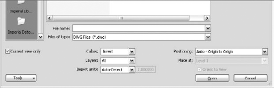
Let's examine the meaning of the settings in this situation:
- Current View Only
When this option is selected, the linked or imported file can be seen only in the view in which it was inserted and is thus considered a view-specific element. In a worksharing-enabled project, this data will be assigned to the view's workset. More often than not, you will want to choose this option to limit the number of views in which the referenced data will appear. If you need this data in other views, you can copy and paste it from one view to another.
If the option is not selected, the linked file can be seen in all views, including 3D, elevations, and sections. In a worksharing-enabled project, this data will be assigned to the active workset. A benefit to using links in a worksharing environment is the ability to create a workset specifically for linked data and uncheck its Visible In All Views option. The CAD file(s) placed in this manner will not appear in every view but are available when you need them by adjusting the workset visibility in the Visibility/Graphics Overrides dialog box.
- Colors
As stated earlier in the chapter, colors don't really matter for linked CAD files being used for model conversion; however, using Invert or Preserve may help distinguish the CAD data from the modeled elements during the conversion process.
- Layers
These options allow you to import or link all the layers, only the layers visible when the CAD file was last saved, or a selected group of layers you choose from the linked file in a separate dialog box. (Layers are a DWG-based terminology. Revit supports the same functionality with Levels from DGN files.)
- Import Units
For CAD files generated in an original program (that is, DWG from AutoCAD or DGN from MicroStation), the Auto-Detect option works well. If you are linking CAD data that has been exported from a different program, such as DWG exported from Rhino, you should specify the units to the respective CAD file.
- Positioning
To maintain consistency in a multilevel project during a CAD-to-Revit coordination or conversion process, you should use Auto – Origin To Origin or Auto – By Shared Coordinates. Origin To Origin will align the world coordinates origin of the CAD file with the project internal origin. Although Autodesk claims Auto – By Shared Coordinates is only for use with linked Revit files, it can be used with CAD files if rotation of true north becomes inconsistent using the Origin To Origin option.
- Place At
This option is available only if Current View Only is not selected; it specifies the level at which the inserted data will be placed.
Once you have data imported or linked into a Revit project, you have several ways of manipulating the data to suit your needs:
- Foreground/Background
This setting only applies to linked or imported CAD files placed with the Current View Only option. With the inserted file selected, a drop-down menu will appear in the Options Bar to adjust whether the data appears above or below your modeled Revit content.
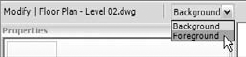
Pay close attention to this option when integrating 2D CAD data with an existing Revit model—sometimes linked or imported CAD data may not appear at all until you set the option to Foreground because of floors or ceilings obscuring the 2D data.
- Visibility of Layers/Levels
The layers or levels within a linked or imported CAD file can be accessed in two ways, the easiest of which is the Query tool. First, select a linked or imported CAD file, and you will see a special Modify panel appear at the right end of the ribbon. Select the Query tool and then pick an object in the CAD file.
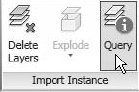
You will see the Import Instance Query dialog box (Figure 8.4). Using this tool, you can hide the layer or level by clicking the Hide In View button. Note that the Query tool will remain active even after you click any of the command buttons in the Import Instance Query dialog box, and you must press the Esc key or select the Modify button.
The second way to make layers or levels in imported or linked CAD files invisible is to use the Visibility/Graphic Overrides dialog box by switching to the View tab and selecting Visibility/Graphics from the Graphics panel. Once the dialog box opens, select the Imported Categories tab, as shown in Figure 8.5. Every imported or linked CAD file in the project will be listed. Expand any listed file to expose the list of layers/levels within that file and use the checkboxes to customize visibility of the link within the current view. Note that this method is the only way to restore visibility of layers/levels that were hidden with the Query tool.
- Graphic Overrides
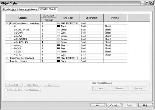
If you need to change the appearance of the content within a linked or imported CAD file, you can accomplish that at the project level or within an individual view. To change a CAD file's appearance throughout the project, select the Manage tab on the ribbon, and click Object Styles in the Settings panel (Figure 8.6). Select the Imported Objects tab and expand any of the imported or linked CAD files to change the color, line weight, line pattern, or material of the layers/levels within the referenced file. Note that changing these properties in the row of the filename does not affect the contents of that file. You can also apply these settings in a specific view using the Visibility/Graphic Overrides dialog box.
- Exploding
Although we do not recommend the exploding of CAD data within a Revit project, you can do it to facilitate the modification of such data. Linked content must first be converted to an import in order to be exploded. You do this by selecting the Insert tab on the ribbon, choosing Manage Links from the Link panel, choosing a listed link, and clicking the Import button. To explode the imported file, select it, and choose Explode


In this section, we will discuss how to import 2D CAD data from platforms such as AutoCAD (DWG) and MicroStation (DGN) or in the generic Drawing Exchange Format (DXF). You can also use files from other software platforms, but only if they are DWG, DGN, or DXF format. Most commercially available CAD programs are able to export in DWG or DXF format.
There are two fundamental ways 2D CAD data can be used with respect to a building project's floor plans, ceiling plans, or site plans:
Using 2D data as backgrounds for BIM conversion
Integrating 2D data with the model
In this situation, we will assume that 2D CAD data will be linked into the Revit model to be converted into building elements. Although the positioning of the files is important, the color and line weights of the imported data are not.
To begin the next exercise, you will need the files c08-Plan01.dwg and c08-Start.rvt. You can download these files from this book's companion website: www.sybex.com/go/masteringrevit2011. After downloading, open the c08-Start.rvt file, and activate the Level 1 floor plan.
Linking Very Large CAD Data
Use caution when attempting to link or import CAD files with vector data very far from the origin. Revit has distance limitations on imported vector data that—if exceeded—may result in a warning, as shown here:
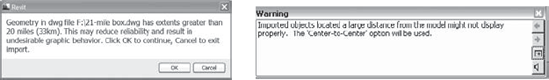
Notice in the warning message above that Revit will automatically use Center To Center positioning if the distance limitations are exceeded. This will preclude you from using the origin of the linked file for Origin To Origin placement. If you must link data that is physically larger than a twenty-mile cube—which may occur in projects such as airports or master plans—you should separate the data into smaller portions before linking. If the data is smaller than the twenty-mile cube but is located farther than twenty miles from its origin, an alternate origin should be coordinated with your project team, and the data should be moved closer to the origin.
If you need to use 2D CAD data as an integrated component of your team coordination, different settings become important. Examples of these types of scenarios might include the following:
Showing light fixture layouts from a lighting designer
Integrating landscape design into a site plan
Reusing existing CAD data for a renovation project
Most of the settings and procedures for conversion apply to the coordination process; however, color and the placement visibility will be different. Because this data will be included in the output from Revit, you will always want the color option to be set to Black and White in the options during linking. It is also likely that some sort of background plans will be exported from the Revit model for use in coordination by one or more consultants using a CAD-based program. The data returned in this process may still contain the background information originally exported from Revit; thus, we recommend agreement to a standard that establishes unique layers for the consultants' content. This will help you select layers to be loaded when linking your consultants' files into the Revit project.
Use these options when linking CAD files into Revit for plan-based coordination:
Current View Only: Selected if data is needed in one view; unselected if data is needed in many views
Colors: Black and White
Layers: Specify (choose only designated layers to isolate consultant's content)
Positioning: Auto – By Shared Coordinates
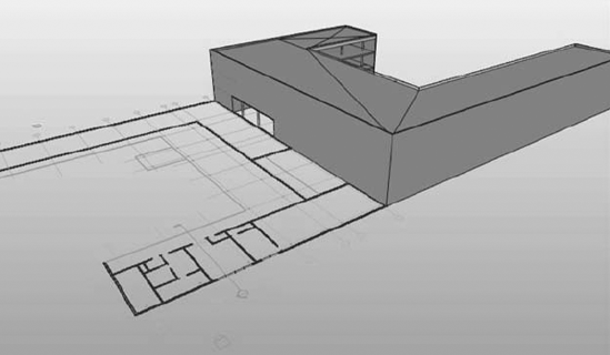
If the Current View Only is not selected, the 2D CAD data will be visible in all other views. This could be a nuisance in views such as sections and elevations; however, you might find it useful to visualize the data alongside the Revit model, as shown in Figure 8.7.
Your company's CAD detail library does not need to go to waste when you implement Revit. External CAD data can be linked into drafting views, allowing you to leverage the powerful view coordination tools within Revit. Entire sheets of CAD details can be inserted to reduce the number of linked files Revit has to reconcile; however, we recommend linking one detail into each drafting view and utilizing Revit's ability to automatically manage the view references with callouts, sections, and detail views. You may also want to name these drafting views with a unique prefix to help keep track of where any linked CAD data might reside. For example, a drafting view might be named CAD-Roof Detail 04. Also refer to Chapter 4, "Configuring Templates and Standards," for additional information on view organization.
In this exercise, you will create a drafting view into which a single CAD detail will be linked. This view can be referenced throughout your Revit model using a section, callout, or elevation view with the Reference Other View option selected in the Options Bar, as shown in Figure 8.8.

To begin this exercise, open the c08-Jenkins.rvt file. You can download this file and the associated CAD file (c08-Detail.dwg) from the book's companion website: www.sybex.com/go/masteringrevit2011.
Switch to the View tab and select Drafting View from the Create panel.
Name the new drafting view CAD Wall Detail 1, and set the scale to 1-1/2"=1"-0".

Switch to the Insert tab and select Link CAD.
In the Link CAD Formats dialog box, navigate to the
c08-Detail.dwgfile and set the following options:Colors: Black and White
Layers: All
Units: Auto-Detect
Positioning: Auto – Center To Center
Click Open to complete the command. If you don't see the linked detail in the drafting view, use Zoom To Fit in order to reset the extents of the view.
Open the Section 2 view from the Project Browser, and zoom to a portion of the view where a floor meets an exterior wall.
From the View tab, select Callout from the Create panel, and select Reference Other View in the Options Bar. Choose Drafting View: CAD Wall Detail 1 from the drop-down list. You'll see the result shown in Figure 8.9.
Double-click the callout head, and you will be taken to the drafting view with the CAD detail linked in the previous steps.
Now that we have discussed using 2D reference data, we will cover how to use 3D model data within your Revit project. There are many valid reasons for modeling outside of Revit, including software expertise, availability of content or generation, and optimization of complex geometry. The following sections will explore some situations in which model data can be shared between programs, including:
In Chapter 9, "Advanced Modeling and Massing," you will learn more about harnessing the impressive modeling tool set in Revit's conceptual massing environment; however, the fast and flexible process of design may lead architects toward a tool in which they have more expertise or comfort. This type of massing design workflow is supported in Revit under the following conditions:
Masses require volumetric geometry to calculate volume, surface area, and floor area faces.
Finely detailed complex geometry should be avoided as the Host By Face tools may not be able to generate meaningful objects.
Refer to Revit Architecture's help system for even more details on using imported geometry in a Mass family.
This example demonstrates the process of creating an in-place mass by linking an external model—in this case, a SketchUp model. You can download the file c08-Mass.skp from the book's companion website: www.sybex.com/go/masteringrevit2011.
From the Massing & Site tab, select In-Place Mass from the Conceptual Mass panel.
Name the new mass family SKP Mass and click OK.
Switch to the Insert tab and select Link CAD from the Link panel. Note that this is a new option for the Revit 2011 platform.
Navigate to the SKP file downloaded from the book's companion web page and set the following options:
Colors: Invert
Layers: All
Import Units: Auto-Detect
Positioning: Auto – Center To Center
Place At: Level 1
Click Open to complete the link process.
Click Finish Mass in the In-Place Editor panel.
Now that a new mass has been created, you can assign mass floors and begin to see calculated results in schedules of masses and mass floors. (Refer to Chapter 9 for more information on these processes.) Calculation of volumes, perimeters, and mass floor areas will work well in this workflow, but be careful when using imported model geometry with the By Face tools because face updates will likely be more difficult for Revit to maintain than with native Revit massing.
Using linking instead of importing enables continued iteration of the form in the original software. In the case of this example, you may edit the original file in Google SketchUp, which is available as a free download from http://sketchup.google.com, or you can download the file c08-Mass-2.skp from the book's companion web page.
If you modify and save the original SKP file yourself, save, close, and reopen the Revit project. Alternatively, open the Manage Links dialog box, select the SKP file, and click Reload. If you want to use the alternate file downloaded from the book's companion web page, use the following steps:
Open the Manage Links dialog box from the Insert tab.
Select the SKP file and click Reload From.
Navigate to the file c08-
Mass-2.skpand click Open.Click OK to close the Manage Links dialog box.
With the modified mass loaded, notice the changes in the Mass Schedule and Mass Floor Schedule.
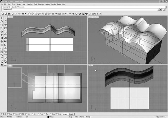
Similar to the data as mass workflow, externally modeled data can be used as a driver for more complex forms. An example might be the need to generate a complex curved roof surface. We will demonstrate this workflow using Rhinoceros by McNeel (www.rhino3d.com) to generate a shape, link the shape into Revit, and create a roof by face on the shape.
As shown in Figure 8.10, a complex surface is generated in Rhino from drawing two curves and using the Extrude Curve Along Curve tool. Note that some reference geometry was exported from a Revit model to DWG and linked into this study in Rhino.

A flat surface model is enough to generate a roof by face in Revit; however, it may be difficult to see the imported surface, so use the Extrude Surface tool to give it a thickness. Once the surface is complete (Figure 8.11), select only the double-curved geometry, choose File
You can download the Rhino file (c08-Roof-Face.3dm) and SAT export (c08-Roof-Face.sat) from this book's companion web page. You can also download the sample Revit project and continue the process as follows:
Open the file
c08-Roof-by-Face.rvtand make sure you are in the 3D view named 00-Start.On the Massing & Site tab, choose In-Place Mass and name it Rhino Roof.
Switch to the Insert tab and select Link CAD. Navigate to the
c08-Roof-Face.satfile downloaded from the book's companion web page.Set the placement options as follows:
Positioning: Auto – Origin to Origin
Place At: Level 1
Import Units: Inch
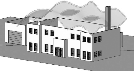
Click Open to complete the link and close the dialog box and then click the Finish Mass button in the ribbon. The mass should be seen above the tops of the walls in the Revit model, as shown in Figure 8.12.
Return to the Massing & Site tab and select the Roof tool from the Model By Face panel. Choose the Basic Roof: Generic 12" from the Type Selector, and click the top face of the mass created in the previous steps. Click the Create Roof button in the ribbon to complete the command and the roof will be generated along the mass surface as shown in Figure 8.13.
Select all the perimeter walls—either using the Tab key or using Ctrl to add individually to the selection.
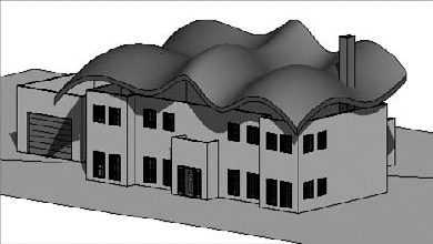
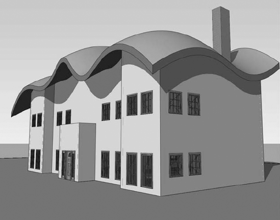
Select the Attach Top/Base tool from the Modify | Walls tab, set the Top option in the Options Bar, and pick the roof by face created in step 6. The walls will connect to the underside of the complex roof shape, as shown in Figure 8.14.
The original shape can be edited in the originating software and will update in Revit via the link if the original exported SAT file is overwritten. To update the roof based on the newly modified massing geometry, select the roof and click the Update To Face button in the Modify | Roofs tab.
Yet another derivation of the reference data workflow supports the use of linked model geometry for specific instances of building components. Examples of this scenario might include a complex canopy structure being designed in SolidWorks or a building's structural framing being modeled in Bentley Structural Modeler. The workflow is again similar to that of using imported data as a mass or face; however, the file format will help you control the component's visualization in Revit. In the previous exercise, we used an SAT format to transfer complex curved geometry from Rhino to Revit; however, a limitation of an SAT file is that the geometry only contains one layer, making it impossible to vary material assignments for different components of the design. We recommend using a solids-based DWG, DGN, or DXF file format, which will maintain a layer structure in most cases.
In the following example, you will create an in-place structural framing component that will act as a placeholder for a consultant's structural model created in Bentley Structural Modeler. You will be using the file c08-Framing.dgn, which you can download from the book's companion web page: www.sybex.com/go/masteringrevit2011.
Launch Revit and start a new project using the
default.rtetemplate.Switch to the Home tab and choose Component
Name the new in-place model DGN Structure.
From the Insert tab, select Link CAD.
Change the Files Of Type option to DGN Files (*.dgn) and navigate to the downloaded file.
Set the following options and click Open:
Current view only: Unselected
Colors: Black and White
Layers: All
Positioning: Auto – Origin To Origin
Place At: Level 1
Click Finish Model in the In-Place Editor panel to complete the process.
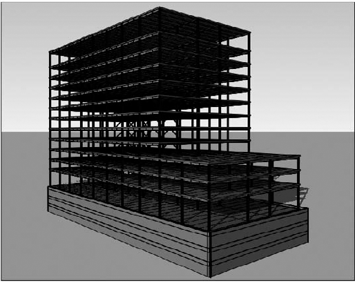
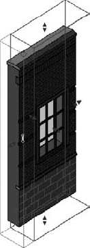
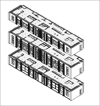
Switch to a 3D view, and you should see the entire contents of the DGN model (Figure 8.15). Because the linked content was created as a structural framing model, the linked data will be displayed similarly to any other structural framing element in Revit. Examine the linked model in different plans and sections to observe this behavior.
Utilizing linked models in DWG, DGN, or DXF format also allows you to modify the graphic representation of the elements within Revit. To adjust these settings, do the following:
When you are using linked model data for custom components, the consistency of the data you bring into Revit from other programs depends on the ability of that software to generate organized information. Some programs utilize layers, and some don't. Recognizing this difference will give you the best opportunity for success in coordination through interoperability.
Of equal importance to importing external data is the ability to export Revit data for use by others. This section will examine various processes for exporting data from your Revit project to other formats. To achieve your desired results when exporting, remember that exporting from Revit is essentially a WYSIWYG (what you see is what you get) process. For example, exporting a 3D view will result in a 3D model, exporting a floor plan will result in a 2D CAD file, and exporting a schedule will result in a delimited file that can be used in a program such as Microsoft Excel.
We will first review the process for preparing a set of files to be exported. This method is similar for almost all exports and will be referred to in subsequent sections.
The first step to any export is to establish the set of files to be exported. The following steps will walk you through the process:
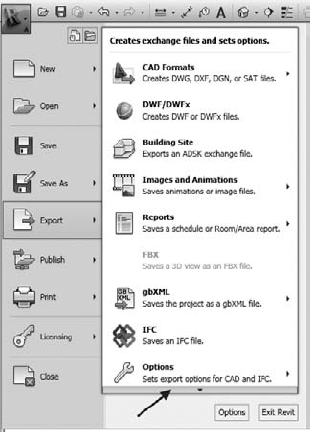
You can find all exporting commands by clicking the Application button and clicking the Export fly-out. As shown in Figure 8.16, check the bottom of the fly-out menu for additional commands available for use.
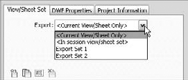
Beginning an exporting command such as DWF/DWFx, you will first see the typical Export Settings dialog box, as shown in Figure 8.17. Notice in the View/Sheet Set tab the Export value is usually set to <Current View/Sheet Only>.
Begin to create your own list of views and/or sheets to export by picking <In session view/sheet set> from the Export drop-down list, as shown in Figure 8.18. Note the listings "Export Set 1" and "Export Set 2" are predefined lists I created for the purposes of this tutorial.
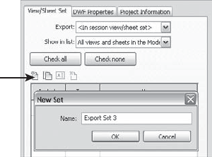
From this point, you can either use a temporary in-session set or create your own named set. We will continue these steps by creating a new set. Click the New icon above the view list, as shown in Figure 8.19, and name the set Export Set 3. Click OK to close the dialog box.
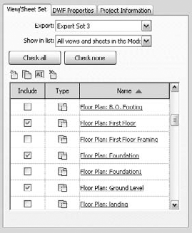
To begin adding views and/or sheets to your new export set, make sure the Show In list drop-down is set to Views In The Model, Sheets In The Model, or All Views And Sheets In The Model (see Figure 8.20).
Select the views and/or sheets you need to export by checking the boxes next to the listed views in the Include column. Remember, you can sort the list by clicking any of the list headers (Figure 8.21).
If you are done creating your list of views to export and don't want to continue exporting, click the Save Settings button; otherwise, click Next.


The subsequent steps in the exporting process are slightly different based on each export format. You will usually see a Save To Target dialog box that allows you to specify automatic or manual naming conventions for multiple exported files. Exporting FBX files or images simply requires a file location and name.
In addition to creating and maintaining lists of views for various exporting tasks, we recommend that you create at least one standardized layer mapping file for CAD format exports. Revit stores these settings in a text file (*.txt) that can be loaded from any location on your computer or network. To access the Export Layers settings, click the Application button and select Export

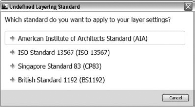
Several exporting templates based on the industry standard layering guidelines are included (Figure 8.23) with Revit Architecture and can be applied by clicking the Standard button in the Export Layers dialog box. Similarly to import settings, you may want to create customized layer export templates and save them with your project data for future reference. Note that export templates will inherit all layer names of linked CAD files in your active project. Because of this, we recommend saving a copy of your export templates in a zip archive in case you need to return to the original template.
Layer names and colors can be customized by directly editing the values within the Export Layers dialog box (Figure 8.24). Notice when a layer's color is modified, the color of all other layers of the same name will update automatically. Layers listed in bracketed italics—for example, {A-WALL-FULL}—are automatically referencing the layer assigned to a parent category. For example, in Figure 8.24, the Cut layer for the subcategory Wall Sweeps will adopt the same layer (A-WALL) as the parent category of Walls.
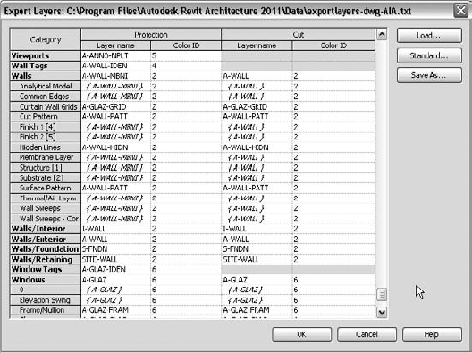
Special layer suffixes can be assigned to Revit model objects that are subject to graphic overrides from phasing. The standard phasing overrides (Existing, Demolished, and Temporary) are listed as object styles in the Export Layers dialog box and can be customized as required. These settings are applied to the end of the specified layer for a given Revit object. For example, if a new wall was set to export to A-WALL, a wall displayed as demolished in a Revit view would be exported to the A-WALL-DEMO layer.
When collaborating with others who require 2D CAD, planning a strategic workflow will allow you to share your Revit data more efficiently and consistently. We highly recommend that you determine and document the scope of data to be shared, the schedule by which it will be shared, and the software platforms to be used on a project. These aspects should be compiled in a BIM execution plan as explained in Chapter 7, "Working with Consultants."
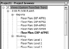
To facilitate the setup and ultimate export of plan data, you can create copies of floor plans and ceiling plans with a standardized naming convention in your Revit project. These should be easy to recognize yet help in building the export list. In Figure 8.25, a series of duplicated plans have been created and named with the EXP- prefix. The rest of the view name conforms to the naming convention specified by the National CAD Standard (www.nationalcadstandard.org).
When it is time to export floor plans or ceiling plans, make sure you are using the most appropriate settings according to the conventions your team has established in the BIM execution plan. You can find these settings in the DWG Properties tab of the Export CAD Formats dialog box, as shown in Figure 8.26.
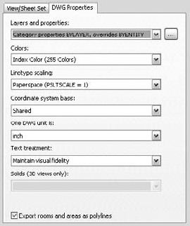
The following are the DWG settings for exporting:
- Layers And Properties
Usually the best option is Category Properties BYLAYER, Overrides BYENTITY because of its fidelity to the original graphic appearance in Revit views; however, if the recipients of your exported data have scripts or macros to convert your data to their own graphic standards, the setting All Properties BYLAYER, No Overrides might be a better choice. This avoids necessary manual editing of object properties to be modified.
- Coordinate System Basis
Any BIM execution plan or project CAD standard will contain specifications for a common origin and coordinate system. When you are exporting 2D CAD data from Revit, the Coordinate System Basis option should be set to Shared. This requires the establishment of a shared coordinate system, discussed in Chapter 7. The Project Internal option might lead to inconsistent results if data from others is being coordinated.
- Export Rooms And Areas As Polylines
This check box is useful if the recipients of your data will need to extract area information from the exported CAD files. Closed polylines are the best vehicle for transferring this data efficiently.
You can also export your Revit model as a 3D model in several formats for use in other modeling software. A frequent destination for such data is Autodesk 3ds Max for its enhanced rendering and daylighting analysis capabilities. This workflow is supported by the FBX export format, which not only includes model geometry but materials, cameras, and lights as well. More generic exports in DWG, DGN, DXF, or SAT formats can provide numerous opportunities for you to become more creative with the presentation of your designs.
Earlier in this chapter we discussed using Google SketchUp for conceptual building massing studies. These studies were imported directly into the Revit environment for further development of a true building information model. Revit model data can also be exported via 3D DWG to Google SketchUp, where visualization studies can be conducted on an entire project or even a simple wall section. In the following exercise, we will create a wall section study from Revit to Google SketchUp using files you can download from the book's companion website: www.sybex.com/go/masteringrevit2011.
Open the file c08-
Sketchup-Wall-Study.rvt.Activate the default 3D view and enable the Section Box option in the Properties Palette for the view.
Set the detail level of the view to Medium.

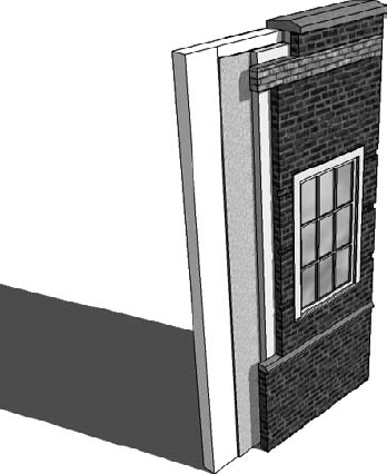
Select the section box in the 3D view and shape handles will appear on each face. Grab the shape handle of one side of the section box parallel to the vertical edge of the wall sample and drag toward the wall until the section box intersects the wall, as shown in Figure 8.27. You should see the layers of the wall structure exposed.
With the section box still selected, right-click and choose Hide In View
Click the Application button and select Export
In the Export CAD Formats dialog box, switch to the DWG Properties tab and set the Solids option to Export As Polymesh.
Click Next and save the DWG file to a location on your computer or network.
Launch Google SketchUp, and choose File
Switch the Files Of Type option to AutoCAD Files, navigate to the file saved in step 8, and click Open.
Switch to the Select tool, select the entire DWG import, right-click and choose Explode. This will allow you to directly edit the elements in the SketchUp environment. Note that other components within the exploded model may need to be exploded again.

Once the DWG model is loaded in Google SketchUp, you can use the Paint Bucket tool to apply materials to individual components, use the Push/Pull tool to hide or expose layers of the wall construction, and use the line tools to customize the profile of the revealed layers, as shown in Figure 8.29.
According to Wikipedia, "Industry Foundation Classes (IFC) is a data model based on a neutral and open specification that is not controlled by a single software vendor or group of vendors. It is an object-oriented file format with a data model developed by the buildingSMART Alliance (International Alliance for Interoperability, IAI) to facilitate interoperability in the building industry." The IFC model specification is registered by the International Standards Organization (ISO) as ISO/PAS 16739 and is currently in the process of becoming the official International Standard ISO/IS 16739. Because of its focus on ease of interoperability between BIM software platforms, some government agencies are requiring IFC format deliverables for publicly funded building projects.
The use of IFC format in a Revit workflow can be useful if you understand its limitations. Some scenarios where IFC exchange may apply and facilitate data exchange include, but are not limited to, the following:
Linking AutoCAD MEP into Revit
Using Solibri Model Checker
Coordination between Revit and Nemetschek Allplan, VectorWorks, or ArchiCAD
You can export the Revit model quite effectively to the IFC 2x2, 2x3 or BCA ePlan Check formats by clicking the Application button and selecting the Export menu. The resulting IFC file (Figure 8.30) can be viewed in a number of programs that can be downloaded at no cost from any of the following websites:
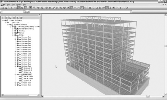
Importing IFC data into Revit is similar to the process for importing 3D CAD geometry; however, the data generated is intended to be more intelligent and editable. Although this method has great potential, the accuracy of Revit's IFC import is highly dependent on the software used to generate the IFC output. We recommend the use of one of the free IFC viewers listed previously to inspect IFC data prior to importing into a Revit project. (Note that only some tools, such as DDS CAD Viewer, have the ability to measure objects in an IFC format file.)
Once you've reviewed the contents of the IFC file, you can open it in Revit and integrate it into your coordination process as follows:
Click the Application button, and select Open
Navigate to the
c08-Structure.ifcfile and click Open.Start a new Revit project using the default template. You will link the saved RVT file into a blank project to simulate the process for a host project model.
On the Insert tab, select Link Revit from the Link panel.
Navigate to the file saved in step 3, and click Open.
If an updated IFC file is received, repeat steps 1–3, and overwrite the RVT file created in step 3. When the host project file is reopened, the linked RVT file containing the imported IFC content will be updated.

Effective coordination between Revit Architecture and AutoCAD MEP frequently relies on the exchange of 3D DWG files of limited scope with respect to the overall project. MEP engineers using AutoCAD MEP will usually manage their BIM with one model file per level. Even though the entire architectural model can be exported to a single DWG model, they may not be able to reference such a large model efficiently. The good news? Your Revit project can be set up to achieve this by creating 3D views with section boxes for each level.
Begin by creating a series of floor plans designed for exporting (discussed earlier in this chapter). In the View Range settings for these plans, set the Top value to Level Above, Offset: 0 and the Bottom value to Associated Level, Offset: 0. Create a 3D view for each level required in the project and rename the views according to your standards. In each duplicated 3D view, right-click the ViewCube and select Orient To View
- Use imported 2D CAD data.
CAD data can be integrated into your Revit project in a number of ways: as plans of existing conditions, as fixture layouts from consultants, or as standard details from your company's library.
- Master It
How can CAD details be used within Revit?
- Export 2D CAD data.
The ability to deliver quality 2D information to other constituents involved in your project is as important as importing it into Revit. Appropriately formatted views, standardized layer templates, and proper coordinate settings will result in happy team members and a smooth coordination process.
- Master It
Does Revit comply with the National CAD Standard?
- Use imported 3D model data.
Model data generated outside of Revit can be integrated into your projects as whole building systems, massing studies, or unique components.
- Master It
How can a building's structural model created with Bentley Structure be integrated into Revit?
- Export 3D model data.
Your modeled elements don't have to remain in the Revit environment forever. Data can be exported to 3ds Max, Google SketchUp, AutoCAD MEP, and more.
- Master It
How can I coordinate my architectural Revit model with an engineer using AutoCAD MEP?
- Work with IFC imports and exports.
Industry Foundation Classes is a vendor-neutral model format designed to support interoperability in the AEC industry. It is widely used by some major BIM platforms available around the world.
- Master It
How is an IFC model integrated into Revit for coordination?