
Nothing is more frustrating than getting into a design program by building the project in Revit only to find out the building is too big and somehow the program still doesn't fit. You think that you've done everything right—walls, floors, rooms, schedules—but somewhere, something is wrong. And you have no idea where to begin to change your design.
Massing is great for avoiding this kind of scenario. By creating the "big" design idea at a macro level, as a mass, you're able to quickly and easily quantify and analyze the results. This allows you to confidently work from general to specific as your design progresses, without starting with actual building elements (which would be too specific too soon anyway).
In addition, massing allows you to create forms and containers to control more granular components. Complex walls, curtain walls, curtain panels, and other elements would be incredibly difficult to make (much less update) without some underlying form to establish and drive their design. Massing is essential for this kind of design and design iteration.
Even though your overall design might not be represented by a complex massing form, it's very likely that somewhere in a more conventional design massing is essential to the success of your project.
In this chapter, you'll learn to:
Create and schedule massing studies
Know when to use solid and surface masses
Use mathematical formulas for massing
You might not think that you need to use massing tools when you first begin using Revit if you tend to design conventional or rectilinear buildings. But you'll quickly find that just because you don't create complex buildings, a lot of buildings contain complex features or parts that require a firm understanding of the massing tool.
Massing is certainly used to create masses, that is, forms with geometric substance (solids and voids). But the massing tool is also used to create complex surfaces that can be used to create relationships to other host elements. Without these mass- or surface-based relationships, it'd be really hard to create and reiterate system families such as walls and curtain walls. You'd essentially have to start over when the design changed. Massing allows you to create a lightweight design idea, evaluate it, and then associate some real-world building elements with the massing element. To change the real-world building element, you change the lightweight design idea first.
Another important thing to know about massing is that masses can be created in both the project environment as well as the Family Editor. There's a lot of overlap of functionality in each case, but there's also a lot of important functionality missing. So, what's the difference?
The main difference as to whether you create massing in-place or in the Family Editor doesn't depend on the kind of shape or surface you want to create. Solid and surface forms can be created in both the project and Family Editor environments. Rather, it depends on how you want to create the massing and how want to change the mass once it's been created.
Generally speaking, there are two ways to create form. The first approach tends to create masses more intuitively; the second approach tends to create masses more formulaically. Intuitively created masses could probably be created right in the project environment as an in-place mass, but if the shape that you're trying to create needs to be driven by formulas, you're probably better off opening the Family Editor and creating the shape there.
When using the intuitive method, you can model just about anything in the project environment, both host and component families. We strongly recommend that you don't model component families in-place unless the condition is quite unique and exceptional, because the moment you need to create another just like it, you will have created a copy. If you have to change both of them, you'll have to change them both manually. It's best to model component families in the Family Editor.
But once in a while you'll have to create a complex host element that can't be created with the standard tools, and you'll have to use the formulaic method. As you've noticed by now, there are no templates in the Family Editor for host (or system) families such as walls, roofs, and floors. If you need to create these, they'll have to be created in the project environment. This can be done in one of two ways: create a mass or surface (using massing) or simply model it in place. If the structure of the wall varies significantly, you'll probably just want to model the wall in place. But if the structure is more consistent, it'll be easier to create a mass or surface form, and then associate the wall with this form.
Note
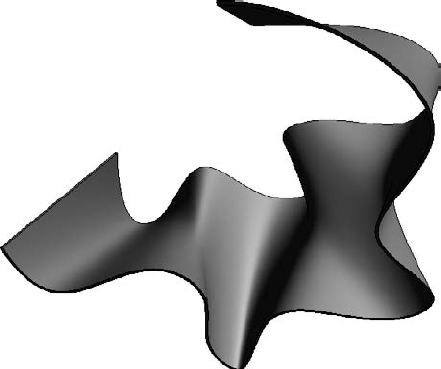
Figure 9.1 illustrates the intuitive method. It was created all the way back in 2001 when a lot of people thought Revit couldn't be used to create complex shapes. This was kind of true for a while, but once blends were introduced, these kinds of complex shapes were immediately possible.
This wall wasn't created by starting with a mass; it was created by creating the blend in-place in the Wall category. Notice how the top and base of the wall are not consistently thick. It's narrower in some places and wider in others as it moves from bottom to top.
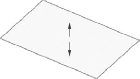
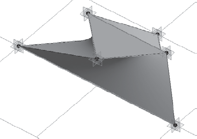
But if the wall was meant to be consistently wide, it would be more appropriate to make the mass or surface first, and then assign the wall to the form (Figure 9.2). Notice how the top and bottom of the wall are the same width overall.
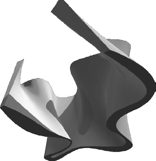
At the end of the day, the previous two figures were created in the project environment through intuitive decision making. There were no formulas or parameters or rules; we just created the shape directly—in the moment, so to speak.
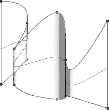
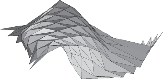
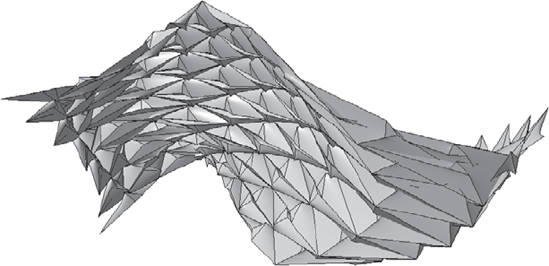
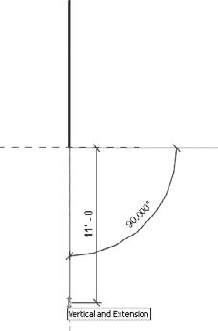
The other way to create a form is to first start to think about the rules that you want to create (and later reiterate) for the form you're trying to accomplish. Figure 9.3 illustrates this kind of form.
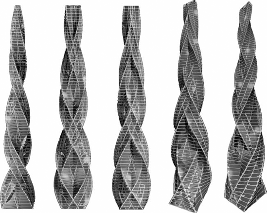
The rules that were created resulted in a form that would programmatically rotate and narrow depending on its relative elevation. Later, geometry was assigned to this form along the edges. Creating this kind of form as an in-place object would be tedious, and modifying it would be extremely time-consuming.
Now we'll talk about creating massing as both in-place and in the Family Editor.
Whether you create masses in-place or in the Family Editor, you're able to generate floor faces (not the actual floors) and schedule important metadata before you've even begun to assign actual geometry to the masses. This is important to do because the masses will be light in your project. You should use them to establish your design idea before committing a lot of complex geometry.
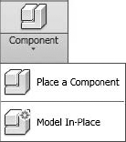
In-place mass forms can be both solid- and surface-based forms. You can start them two ways. The first way is to select Component
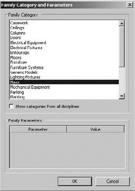
When you select this option, the dialog box in Figure 9.5 appears. Be sure to select the Mass category.
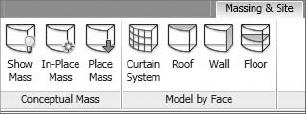
The other way is to select the Massing & Site tab, as shown in Figure 9.6. From the Conceptual Mass panel, select In-Place Mass. In either case, when you start to create the mass, you'll want to have the Mass category visible (it's turned off by default in all views).
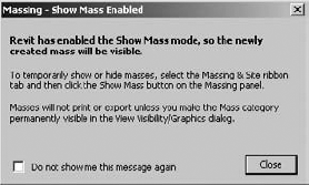
Rather than confuse you by allowing you to create objects that wouldn't be visible, Revit prompts you to turn the category on (Figure 9.7).
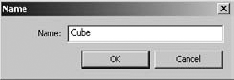
Once you close this dialog box, you'll be given the opportunity to name your in-place mass. In this case we're going to name the mass Cube (Figure 9.8).
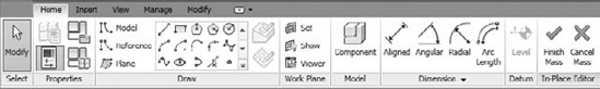
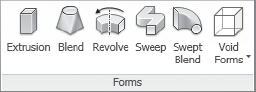
After you've named the mass from the previous steps and clicked OK, you'll be shown the contextually specific Massing toolset. The Home tab contains the tools that you'll use to create solid and void geometry as well as surface-generated masses, as shown in Figure 9.9.
When you're finished creating your mass, you'll have to select Finish Mass (or Cancel Mass) in order to return to the regular project environment.
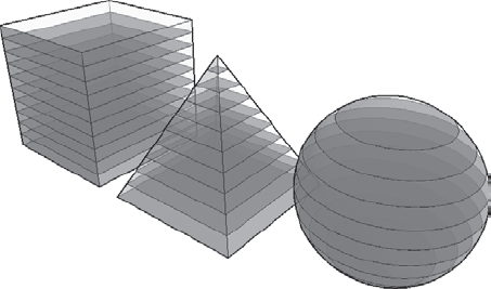
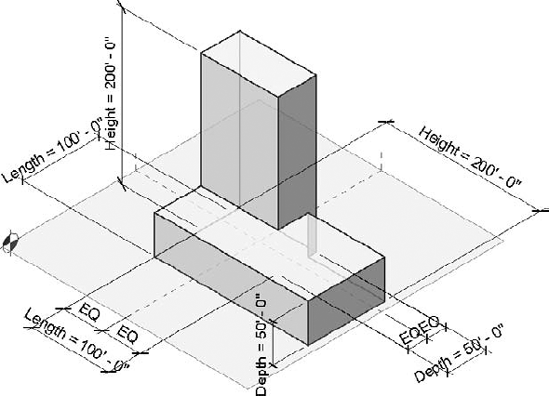
In Figure 9.10, we've created three masses: Cube, Pyramid, and Sphere.
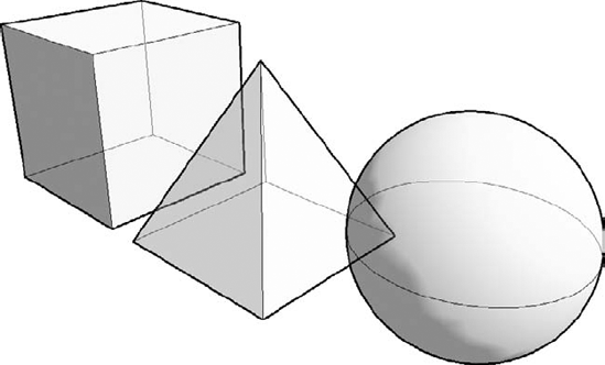
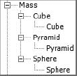
All three of these shapes have been created as completely different masses, not within the same in-place session. As each form was finished, the mass was completed and the process was repeated for each mass. The difference is that in your Family Browser, each mass will show up as a separate line item (Figure 9.11).
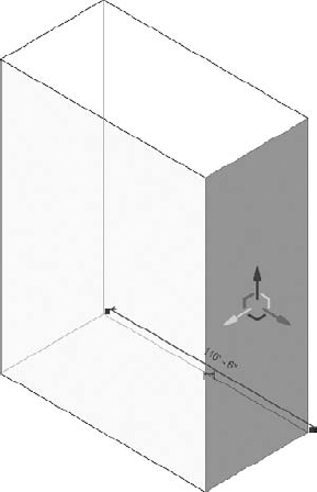
Starting with the cube, its dimensions are 100" x 100" x 100" (about 30m x 30m x 30m). The base of the pyramid is the same size as the cube with equal sides tapering to the same height. And the sphere is the same width as the cube.
Note
Once each shape is complete, it's important to understand how to create floor area faces. Keep in mind that the process would be the same for in-place masses as those created in the Family Editor.
To create floor area faces, follow these steps:
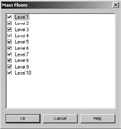
Create more levels above the two default levels. Do this as shown in Figure 9.12. This will give you a total of 10 levels.
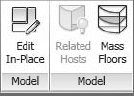
Now select all the masses and click the Mass Floors button in the contextual Model panel (Figure 9.13).
Select all the levels, as shown in Figure 9.14.
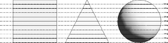
The solid masses will be intersected by floor faces, as shown in Figure 9.15. Now the masses and floor faces can be calculated and scheduled.
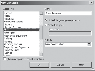
Select Schedules from the View tab, and you'll be given the option to schedule both Mass and Mass Floor (Figure 9.16). In this case we'll schedule the masses so we can do a comparative analysis between the different mass types.
Select the categories as shown in Figure 9.17 and add them to the scheduled fields.
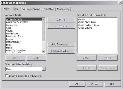
For this example, we'll also show you how to create two calculated values. This will allow you to calculate the overall volume compared to the floor area, as well as the overall surface area compared to the floor area. Schedules like this will be helpful during the early design process to help you understand how efficient the space of your design is compared to the volume and surface area required to contain that space.
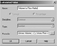
Create the volume-to-floor ratio. Note the formula as shown in Figure 9.18. To keep the units consistent, you divide the gross volume by 1 before dividing by the gross floor area.
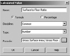
Create the calculated value to compare the surface-to-floor ratio, as shown in Figure 9.19.
Finish both calculated values and finish the schedule. You'll see the Mass Schedule as shown in Figure 9.20. Notice that proportionally, a sphere and a cube have efficient floor areas compared to their required surface area and volume.
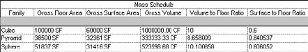
On the other hand, the pyramid mass will require significantly more surface and volume to create the same relative surface area as a cube or a sphere; as a result, it takes far more surface area than a cube to contain the same space. Perhaps this is why pyramids aren't a common building mass—it's too expensive. Pyramids only pay for themselves if the labor is cheap or the owner has a lot of money to spend.
If you want to download this file, it's in the Chapter 9 folder and is named c09_Mass_Schedules.rvt.
How you create masses (surface or form) differs significantly from the UI used to create other standard content in Revit. When you're creating standard project content, you tend to think of the form that you're creating and then start to create that form in a discrete mode that isolates you from doing anything else until the form making is complete (Figure 9.21). In some ways, this is Noun > Verb approach: you know the form that you want to create and then you create it.
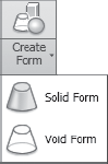
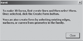
Creating massing in Revit still requires that you know the form that you intend to create, but you're not required to select a particular Noun-type to get started. Rather, you simply start by creating the sketch-based elements that would define your shape. Then you select them as a group and choose the Create Form option (Figure 9.22). This will allow you to create both solids and voids.
In the event that you don't select enough information for the Create Form command to make sense, you'll get the warning shown in Figure 9.23.
Both solid and surface may be created from model lines or reference lines (Figure 9.24). But the differences are important. Keep in mind that your ability to further iterate the form that you create depends on whether you use model or reference lines to generate the form, even though the forms created may at first look exactly the same.
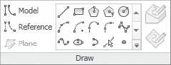
If your intent is to simply create a form that is not likely to require further iteration or rule-based parameterization, using model lines is fine. But if you intend to parameterize the form with formulas and other rules, it's best to start with reference lines. Figure 9.25 shows the subtle graphic difference between the two line types. The model line is on the left, and the green reference line is on the right.
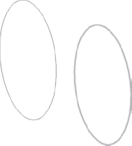
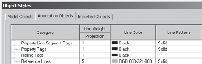
Since the difference is so subtle on the screen, we recommend that you give your reference lines more thickness and lighten the default green color so that they stand out better. This can be done from the Object Styles settings (Figure 9.26).
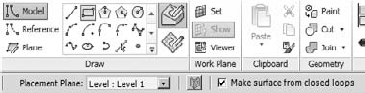
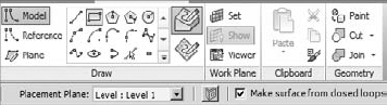
Because reference lines allow for more flexibility, we recommend that you use reference lines (even when you don't think you need to). Another reason is because you can create faces from closed loops if you use reference lines (Figure 9.27). This option isn't available when you select model lines. Selecting a closed loop of model lines will only create a form (solid or void), never a face.
All of the shapes that you'll create in this chapter are going to be done using reference objects.
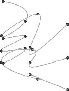
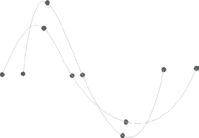
Figure 9.28 shows a number of line types: Spline Through Points, Spline, Curve, and Line.
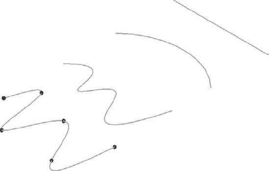
As you can see in Figure 9.29, each of these reference lines have different control points that allow for further control.
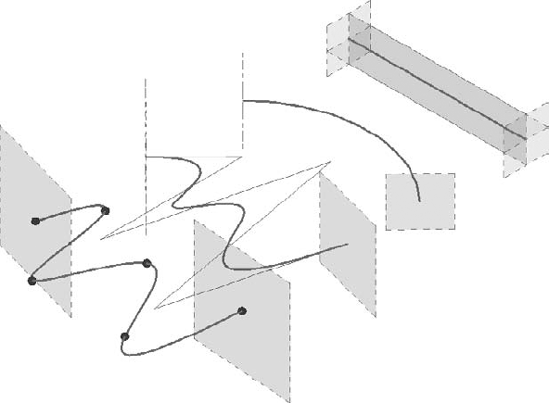
Since these are not closed loops, the form that will generate from each of these segments will only be face or surface (Figure 9.30). This is done by selecting each of the lines (one at a time, not together) and then selecting Create Form.
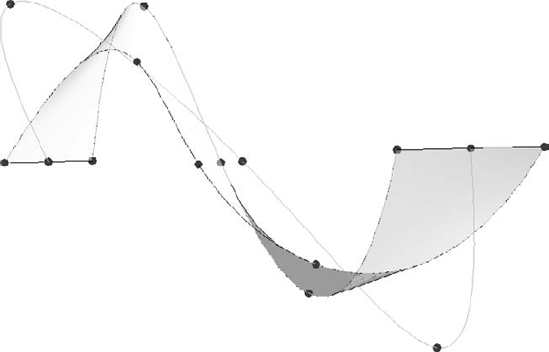
You can also create surface-based forms from more than one line at a time. The result is a surface that can be controlled in more complex ways than a single line.
For example, we'll take the Spline Through Points. The form on the left creates a face that is controlled by a single reference line, whereas the form on the right is a face controlled by two (and it could be more) reference lines (Figure 9.31).
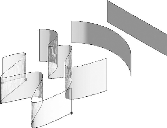
Moving the location of the control points on the form on the left maintains a consistent height to the top of the surface previously generated, whereas moving the control points of the surface on the right will create a surface that varies in height (Figure 9.32).
After a surface is generated, it's also possible to add more profiles, as illustrated by Figure 9.33.
After the profile was added, the location of the profile was moved in order to create a bulge in the surface (Figure 9.34).
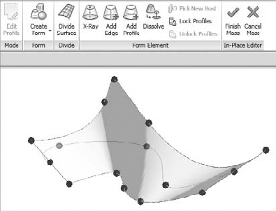
The fourth iteration of the form has been created by selecting the surface and then selecting the Dissolve tool (Figure 9.35). This will remove the surface (or solid form) but leave you with all the references used to create the form.
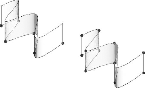
Once the face has been dissolved, another reference Spline Through Points was added between the upper and lower reference splines. The result is shown in Figure 9.36.
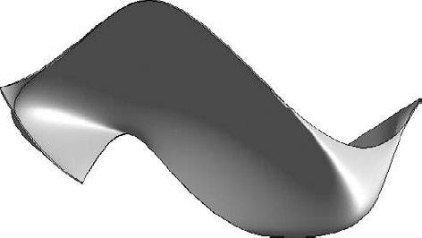
Selecting all three references and then selecting the Create Form tool will stitch them all into a new single surface (Figure 9.37).
Selecting the points within the middle reference will allow for even more complex surface control (Figure 9.38).
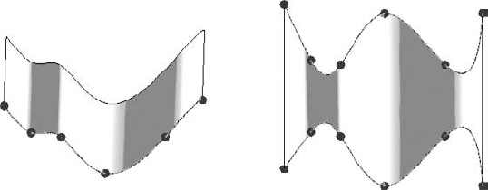
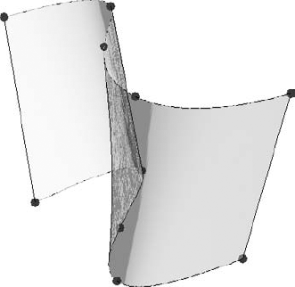
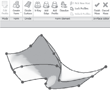
Keep in mind selecting all the splines and then creating the surface will result in very different forms than if you were to sequentially select only adjacent splines (Figure 9.39). The result is that the surface form isn't interpolated as smooth between the upper and lower splines. Instead, a distinct edge is created between the two splines.
As you can see, it's easy to create complex surface forms in Revit using reference lines. Now let's begin to create complex forms using reference planes.
As discussed earlier, creating solid masses isn't done by creating a particular type of form and then entering Sketch mode. Creating the necessary references and then evoking the Create Form tool creates mass forms.
First, you don't have to create solid forms. You can also create surfaces, not only from lines but also from closed loops. Figure 9.40 illustrates this.
Even if you create a surface, you'd still have the option to convert it into a solid mass (Figure 9.41) by selecting the surface and using the control arrows to pull the surface into a three-dimensional shape.
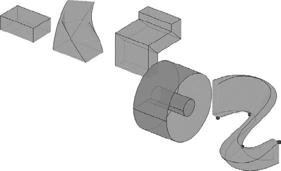
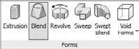
Now let's create each of the reference shapes necessary to create each of the familiar forms in Revit (Figure 9.42). From left to right, these shapes will create Extrusions, Blends, Sweeps, Revolves, and Swept Blends.
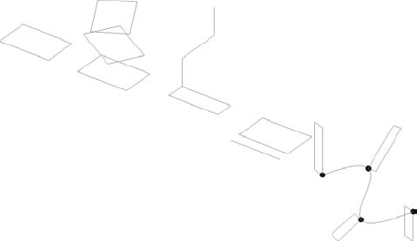
Figure 9.43 shows the resulting forms that are created from each of the references. You would also create voids from the same reference shapes. If you want to download this file for further investigation, it's named c09_Massing_Types.rvt.
All of these mass forms contain parameters and controls relative to their form. We'll now explain how to create surface and solid forms intuitively in the project environment.
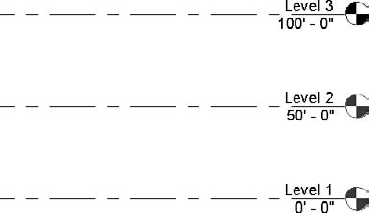
Since this is an intuitive mass form, we'll cover how to create a surface and then assign host elements to the surface. This is a great way to create complex walls and roofs. Then we'll explain how to assign patterns to the surface. Start by opening a new project, and create a third level, as shown in Figure 9.44. We'll use these levels as controls for the Spline Through Points that will generate our first surface.
Select In-Place Mass and go to a top 3D view. Then create a Spline Through Points as shown on Level 1 (Figure 9.45). Although this might seem like a simple shape, the resulting form will be quite complex—just be patient!

Now create another Spline Through Points using Level 3 as a reference, as shown in Figure 9.46. Since you're working in a 3D view, you'll be able to see both splines at the same time.
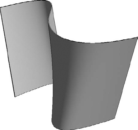
Now rotate the view so that you can see both splines. Select them both and then select Create Form, as shown in Figure 9.47.
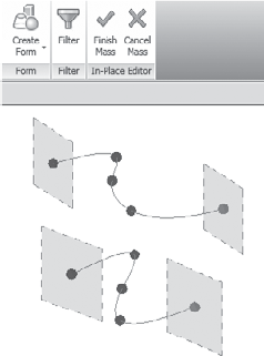
Figure 9.48 shows the resulting surface.
Note
Now you'll create a wall by face and assign it to this form. Go to the Home tab and select Wall By Face, as shown in Figure 9.49.
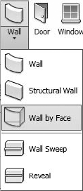
Figure 9.50 shows the resulting wall. The mass surface has been turned off in order to show only the wall.
Now let's return to the in-place mass and change the references. Before you do this, you may want to hide the wall so that only the mass and its references are shown.
By selecting each of the controls, you'll notice you can move them in x-, y-, and z-directions. Go ahead and adjust the controls as shown in Figure 9.51.
Now finish the mass and unhide your wall in the view. Select the wall and then choose the Update To Face option (Figure 9.52).
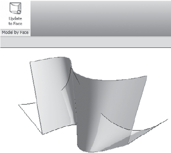
The wall will update to conform itself to the modified face, as shown in Figure 9.53.
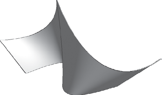
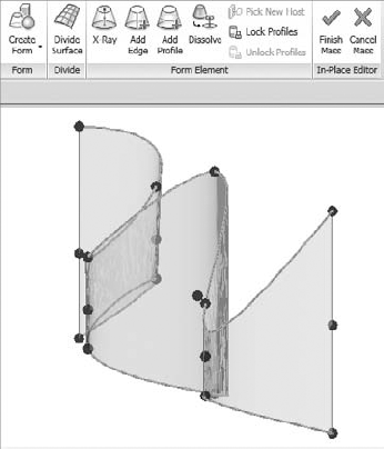
Now hide the wall, select the mass surface, and return to editing in place. Add another Spline Through Points using Level 2 as a reference, as shown in Figure 9.54.
Select the surface and you have the option to dissolve the surface (Figure 9.55). Go ahead and do this. Then select all three splines and re-create the surface.
Once the surface has been revised, finish the family and update the wall as done previously. Your updated wall will not look exactly like Figure 9.56. What's important is that you grasp the principles and the process. If the changes you made were so complex that the wall can't be updated to match the new face, just delete it and re-create it.
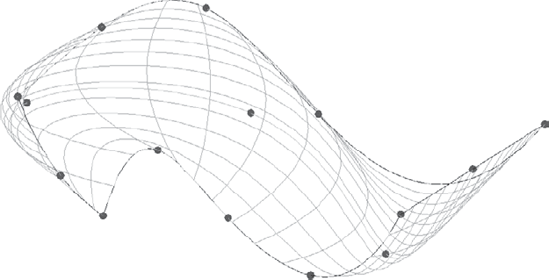
Three steps are involved in assigning a pattern to a mass surface. First you divide the surface, then you assign a pattern to the surface, and finally you assign a component to the pattern.
Rather than start from scratch, create a copy of the surface previously created. Now select the mass surface and enter Edit In-Place mode. Select the surface. Be sure to delete the wall from the copied mass since you'll only need the surface.
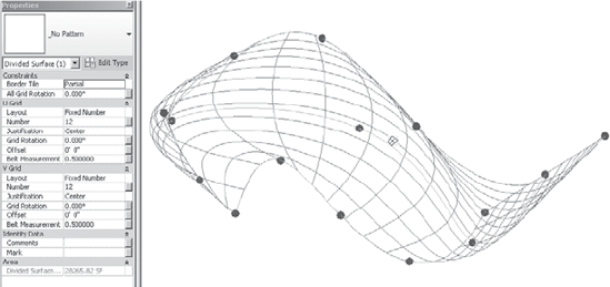
While in Edit In-Place mode, select the surface and choose Divide Surface from the contextual menu (Figure 9.57).
The default divided surface will look like Figure 9.58.
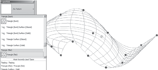
Once the surface has been divided, you can assign a pattern to the surface. The pattern will not contain any geometry; it's a lightweight method of resolving the eventual surface that will be replaced with more resolved geometry.
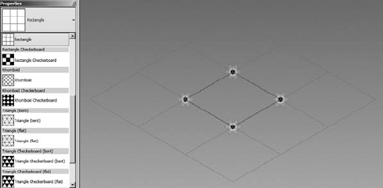
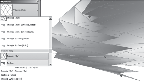
Select the surface and you'll see that no pattern has been applied, as shown in Figure 9.59. Go ahead and experiment with assigning different patterns from the Properties pull-down list.
Eventually, select the Triangle (Flat) pattern (Figure 9.60).
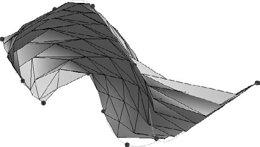
The resulting surface will be faceted with an analytic triangular pattern (Figure 9.61).
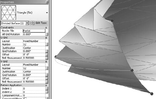
Take a moment to investigate the edge conditions of your analytic surface. There are three options: Partial, Empty, and Overhanging. Select the surface and enter Edit In-Place mode to investigate these three options.
The Partial option allows the triangulated surface to align with the edge of the mass surface (Figure 9.62).
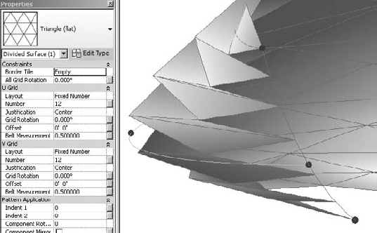
The Empty option doesn't allow the partial panel to be created (Figure 9.63).
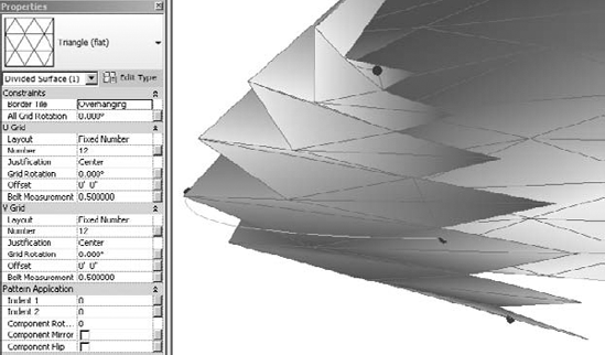
The Overhanging option completes the partial panels to extend beyond the mass surface (Figure 9.64).
Select the Overhanging option. Now exit Edit In-Place mode.
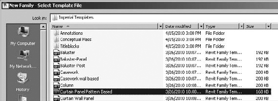
Now you're going to create a pattern-based panel. Start a new family component and open the Curtain Panel Pattern Based (Figure 9.65).
Then follow these steps:
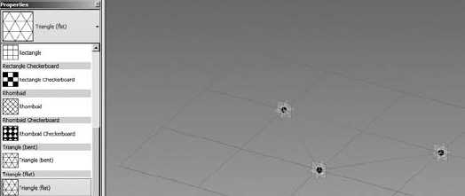
To keep things simple, every pattern-based family that you'll need to create is in this family template. Just select the grid that contains the reference lines and you'll be able to select from all the panel options in the Properties tab (Figure 9.66).
Select a few different options from the pull-down menu and you'll notice that the patterns will change accordingly. Eventually you'll want to select the Triangle (Flat) type, as shown in Figure 9.67.
Apply the template and then update the panel and reload it into your project. This process is important, because if something breaks you'll know which step to reconsider.
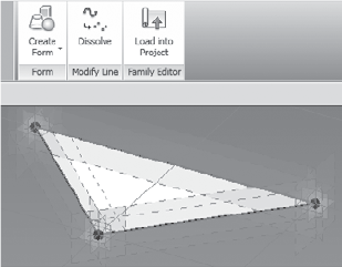
Select the reference planes and then select Create Form. Again, only create the surface, not the geometry (Figure 9.68). Save the family (we've called it
Testing.rfa) and then load it into your massing project.To assign the panel that you just created to the massing form, you need to select the mass and enter Edit In-Place mode. Once you've done this, select the mass again and open the Properties pull-down menu for your mass surface. Notice that in addition to the options for assigning a pattern, you can now assign geometry (Figure 9.69).
Assign this component to the mass. Then exit Edit In-Place mode. Now hide the mass so that only your panel will show (Figure 9.70).
Return to the panel family. It's about to get very interesting!
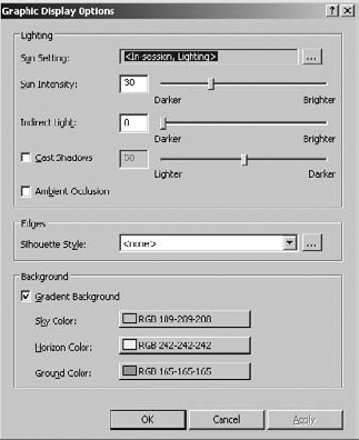
Select all three reference points and copy above the work surface, as shown in Figure 9.71. You can use graphic display options to turn off the gradient background.
Go to a top view and move the points similar to Figure 9.72.
Join the reference points with new reference lines, as shown in Figure 9.73.
Select all the reference lines and create a new form. This will result in a blended form, as shown in Figure 9.74.
Reload the family into the project. Your components will update, creating a surprisingly complex form (Figure 9.75).
By revisiting the family and updating in the project, you can create interesting and complex forms. In Figure 9.76, the panels were created by associating a simple extrusion with a series of reference lines that were offset from the original sketch.
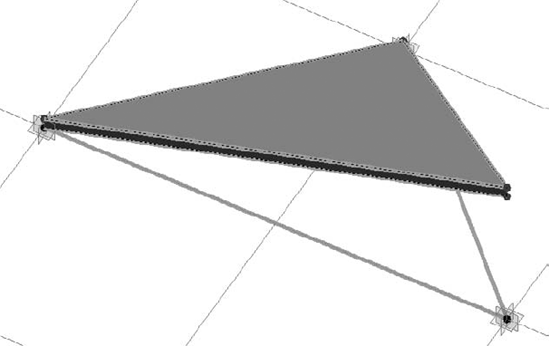
Figure 9.77 shows the resulting family, which has been assigned to a newly created blended surface. If you want to further investigate this project, download the c09_Intuitive_Massing_Surface.rvt file in the Chapter 9 folder.
Of course, creating complex form-driven systems isn't for everyone or every project. But we think that CNC and other forms of rapid prototyping are going to make mass customization increasingly approachable over the next few years.
And if you are interested in generative form making, head over to Zachary Kron's blog. He works in the Revit factory as a software analyst. His blog is at http://buildz.blogspot.com/ and his YouTube channel is www.youtube.com/user/zachkron. He's a great source of geometry, rule-based customization, and in some cases, API-driven customization.
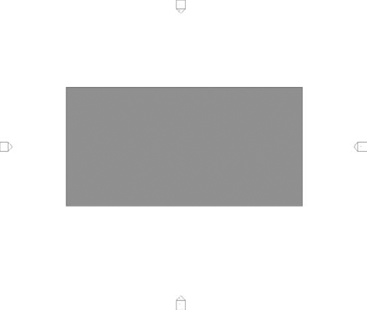
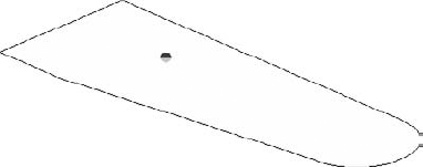
Creating in-place mass solids is quite easy once you understand the process of creating and modifying the various forms in Revit. Let's start by entering in-place massing mode and select a rectilinear shape created from model lines (Figure 9.78). You should also select the option to make a surface from the closed loops that are being created. The other option would be to not make a closed loop, but you're creating a simple extrusion (initially), so this will save a step.
Sketch a form similar to the one shown in Figure 9.79. Specific dimensions are not important; it's really more about the proportions.
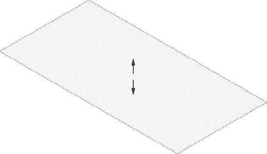
Open the default 3D view and select the face of the surface that you just created. When you select this surface, controls become available that allow you to pull the surface into a solid (Figure 9.80).
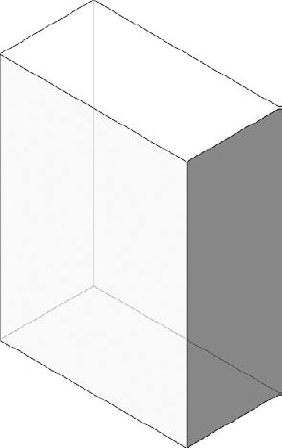
Pull the surface up until it resembles the form shown in Figure 9.81. Again, it's more about proportion than dimensions.
There are a number of shape handles that allow you to modify each face, edge, and intersection. Simply hovering over each face, edge, and vertex will highlight the appropriate control. You may also find it useful to tab through to select the desired control.
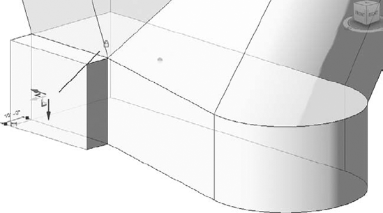
If you select a face, you'll be given the control shown in Figure 9.82.
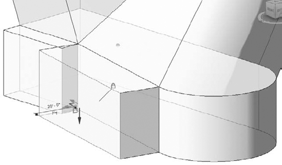
Selecting an edge will give you the ability to modify the edge of a form (Figure 9.83).
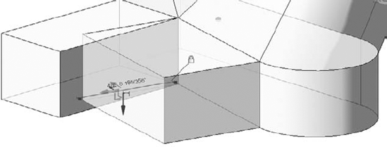
Selecting the intersection allows you to modify the location of a vertex (Figure 9.84).
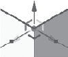
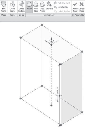
The control arrow allows you to modify the selected element parallel in the direction of the arrow, while the angled indicators of the same colors as their corresponding arrow will allow you to modify the location of the selected element perpendicular to the arrow (Figure 9.85).
First, let's turn on X-ray mode so we can see any of the profiles and controls (Figure 9.86). X-ray mode is helpful for seeing all of the controls that are available as well as the trajectory control of the extrusion.
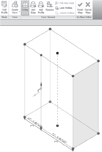
Now that X-ray mode has been enabled, let's look at the options that Revit provides for turning a rather simple, extruded form into something complex. An edge (Figure 9.87) may be added to an existing form that is from vertex to vertex or parallel with the trajectory of the form (shown as a dotted line from the upper to the lower face).
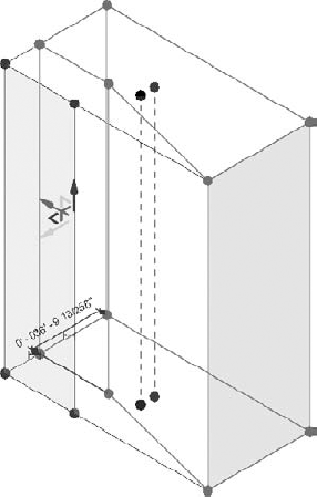
Once the edge has been added, you may push or pull the face adjacent to the new edge, as shown in Figure 9.88.
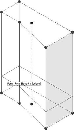
You may also push or pull the edge that has just been created, which will stretch both adjacent faces (Figure 9.89).
Pushing or pulling the edge that is perpendicular to the edge previously created will create curved and warped surfaces (Figure 9.90). This is fine, since the form that we're creating can be rationalized later when adding a pattern to the surface.
But if you'd rather rationalize the form now (and in doing so remove any warped surfaces), then add another edge from vertex to vertex, as shown in Figure 9.91. This will force the faces to become triangulated and planar, as three points define a plane.
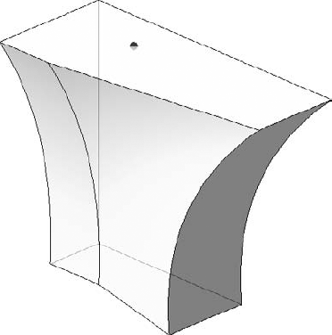
Pulling the top edge away from the vertical plane of the form results in a more dramatic form, as shown in Figure 9.92. Again, it's not necessary to maintain the exact dimensions; it's about trying to keep the proportions appropriate. This is what intuitive form making is all about!
Using the Dissolve function (Figure 9.93) will remove the mass solid and leave behind the analytic profiles that define the solid. The dot in the center of each plane is a control that will allow you to edit the elevation, rotation, and location of the shape.
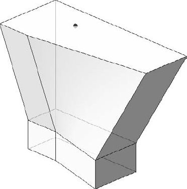
Selecting the profiles together and then choosing the Create Form command will stitch the form back together in a way that interpolates the shape as more of a lofted blend (Figure 9.94). You could also add more profiles to the shape.
However, if you select only two profiles at a time, then the following occurs (Figure 9.95). This form was created by first selecting the two bottom and middle profile and then creating the form. Then the middle and upper profiles were selected and another form was created. The result is straight—rather than curved—interpolation between the profiles.
Rather than select either of the two previous options, let's alter the front edge of all three profiles. Start by deleting the existing edge (you'll have to tab to select just this edge) and then delete as shown in Figure 9.96.
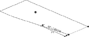
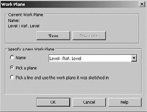
Now you'll want to draw a fillet arch on to rejoin the two remaining edges. To do this you'll have to set the work plane of the shape as shown in Figure 9.97. Just tab through until the horizontal work plane is highlighted and then select it.
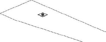
Once the work plane is selected, you'll be able to draw additional model lines. In this example, we're using a fillet arch to connect the lines (Figure 9.98). We'll do the same thing for the other two shapes.
Now select the lower two profiles and choose Create Form. Then do the same with the upper two profiles. Finally, you'll want to remove any blends by adding an edge to the opposing edges.
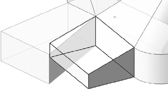
Creating additional mass solids is easy. You can select an existing face and then select the Create Form command, as shown in Figure 9.99.
The same Create Form command was used to create the form shown in Figure 9.100.
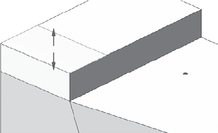
In Figure 9.101, we've extended both faces considerably from their initial depth after using the Create Form option. Notice the locked relationship, which will only allow the faces of the form, not the edges or vertices, to be manipulated. In other words, you wouldn't be able to push or pull the top of the form up. This restriction can be removed by clicking the lock icon.
Once unlocked, the edge of the face is easily moved down to give a slope to the edge at the front of the form (Figure 9.102).
There will be many cases when creating existing geometry from an existing face will give you more mass than you need in your model. In these cases, it's simply a matter of drawing more model lines on the surface of the existing form. Then you'll be able to quickly and easily push and pull the faces, edges, and vertices of the resulting form (Figure 9.103).
The in-place solid mass is finished, and the masses from Figure 9.102 have been joined so that the edge between the two masses is now visible (Figure 9.104). Go ahead and finish the in-place solid mass and return to the regular project environment.
Once you're out of In-Place Massing mode, you'll notice that if you select the model, many shape handles simultaneously appear in the form of solid blue arrowheads (Figure 9.105). You can use shape handles to push and pull your solid mass, but you won't be able to modify edges or vertices without reentering In-Place Massing mode.
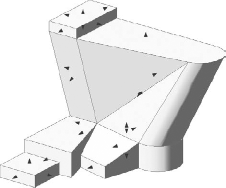
Figure 9.106 shows the finished mass in a perspective view. Both solids and voids can be used to complete a mass form. Whereas solids will add more geometry, voids will remove geometry from your mass.
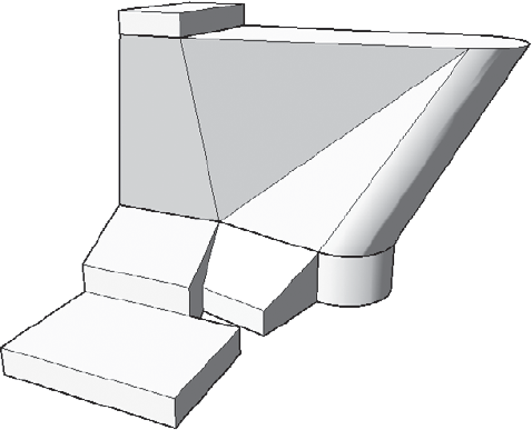
To demonstrate this, we'll return to In-Place Massing mode and create another face on the top of the existing form (Figure 9.107).
Rather than create a void, start by creating a solid, even a solid of a different color and category (if necessary) to keep things clear during your design iteration.
Select the solid mass and convert it to a void, as shown in Figure 9.108.
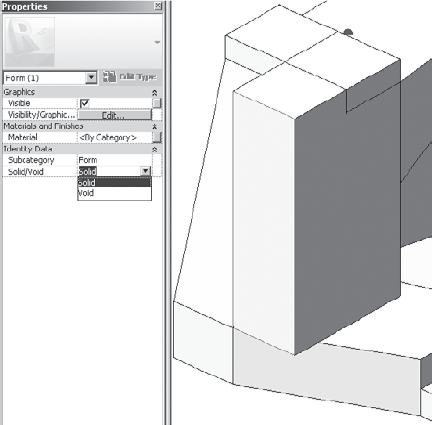
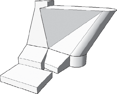
Figure 9.109 shows the result of the void cutting the solid. Keep in mind that if you want to convert the void back to a solid, you'll have to un-cut any geometry that was being cut by the void. But the nice thing about this technique (converting solids to voids and then cutting) is that you've selectively cut only the solids that you wanted to cut. Had you modeled the void as a void, you would have found that the void was cutting many solids and you'd have to un-cut solids that weren't even overlapping with the void!
Overall, creating solids masses intuitively is a great way to establish, analyze, and visualize your overall design idea. As you saw earlier in the chapter, mass floors allow you to even quantify gross floor areas before you've committed to geometry.
Furthermore, it's possible to put different intuitive massing ideas inside different design options (covered in Chapter 11), so that many ideas can live in a single Revit project file. Simply initiate worksharing and create worksets for each study mass. Multiple team members will be able to see one another's work at the same time and in context with their design ideas. This is the holistic kind of team approach to design information that makes massing in Revit a unique and valuable design tool. If you'd like to investigate this file further, you can download the file c09_Intuitive_Massing_Solid.rvt from the Chapter 9 folder.
Next we'll investigate parametric and formulaic solid mass creation in the Family Editor.
Formula-driven massing can be done in the project environment. But the challenge is that you have to work in context of the project, and all the parameters, formulas, reference planes, and lines can start to get in the way. Therefore, having the option of creating form-driven masses in the Family Editor without the clutter of the project environment can help you focus on what you're trying to accomplish.
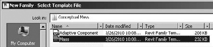
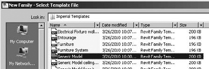
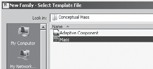
You'll want to make sure that you open the right family template. The mass template is in the conceptual mass folder (Figure 9.110). Don't start with generic model or some other template.
Also, turn off the gradient background that's on by default in the graphic display options (Figure 9.111). You can keep this on if you like, but the images will print better with the option turned off.
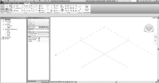
Overall, the UI is not too dissimilar from the project environment. It's like you're creating masses in-place—except that you're not in the project environment, you're in the Family Editor. One significant difference that you can see is that there is a single level and two reference planes, which also define the origin for massing family (Figure 9.112). So, keep in mind that when you reload this family into your project it will update relative to the origin in the family.
In this example, you'll start by creating a simple mass and then add parameters and test the results. Follow these steps:
Create this simple mass using model lines on level one (Figure 9.113). You can save an extra step by selecting the Make Surface From Closed Loops option.
Once you've created the surface in plan, go to the default 3D view and then pull the surface, as shown in Figure 9.114. Again, don't worry about the actual dimensions. Just get the overall proportions close.
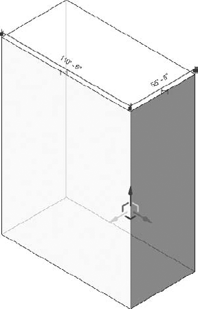
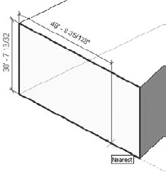
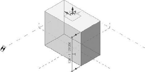
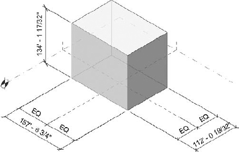
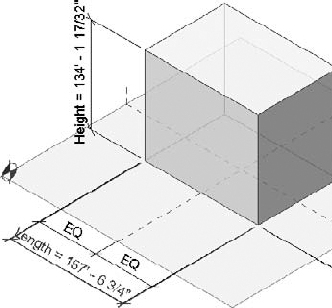
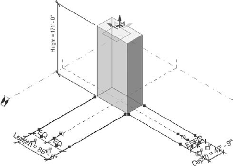
Now you'll dimension the form. Be sure to maintain a relationship to the insertion point of the mass template by using a continuous dimension string set to equal (Figure 9.115). Then dimension the overall dimensions in x, y, and z directions.
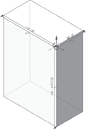
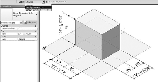
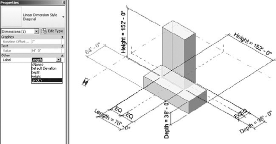
Now you'll add parameters to the overall dimensions. Simply select a dimension and you'll be shown a contextual menu that allows you to associate a parameter with the dimension you've just selected (Figure 9.116).
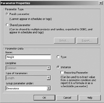
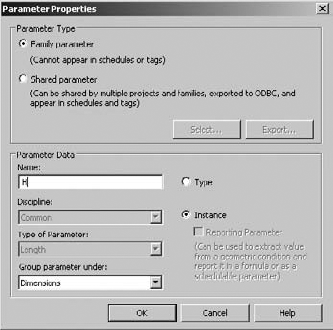
Label this dimension height, and make it an instance parameter (Figure 9.117). If you had many massing elements of the same type loaded into your project and you wanted to control all of them with the same value, this could be a type parameter. But for this example, an instance parameter is fine.
Once you have all your dimensions associated with parameters, your project should look similar to Figure 9.118. That's because as you associate parameter values with your dimensions, the parameter name will display along with the dimension. This is helpful when you need to know which parameter is associated with which dimension.
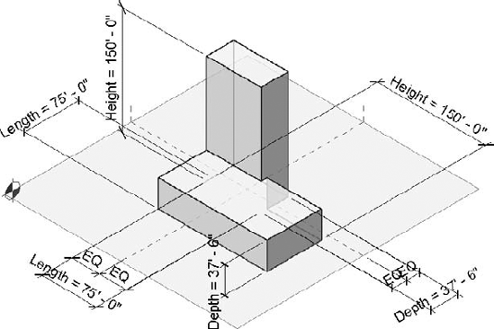
Now it's going to start to get interesting. Rather than maintain independent instance parameters for each dimension, we're going to associate formulas with the length and the depth values. Go ahead and do this as shown in Figure 9.119.
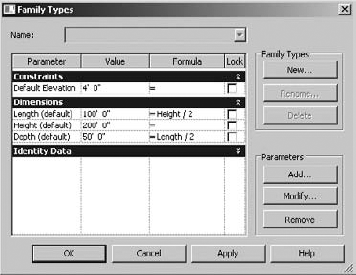
Now your entire mass family can be proportionally controlled simply by adjusting the height parameter (Figure 9.120).
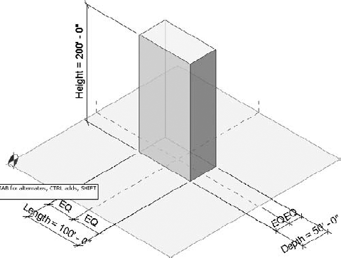
This proportional control can be accomplished in one of two ways. First, you can select the height dimensional value and change the dimension (Figure 9.121). This is desirable when you want to edit a value to an exact amount.
But in many cases, you'll still want to intuitively control the shape of the form first, and then when you get an idea of what looks right, set the resulting dimensional value to a more reasonable figure. This is done by selecting the top face of the form and pushing or pulling the control arrows until you get it close (Figure 9.122). Notice that each time you release the arrow the form adjusts in all dimensions (since the other dimensions are being controlled by formulas related to the height dimension).
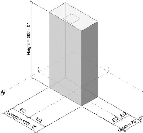
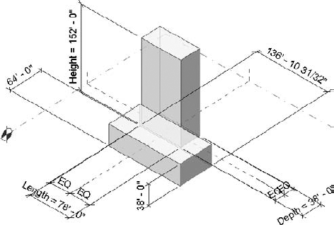
You can experiment further by creating more geometry at the base of the initial mass:
Dimension the form as shown in Figure 9.123.
Associate the dimensions of this second form to the dimensions that you already created (Figure 9.124). What's terrific about this is that as you change a single value, the overall form will proportionally grow or shrink.
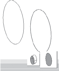
Ultimately this technique of associating parameters with other parameters is a great way to quickly and easily maintain important and interesting formal relationships between masses. Notice how the two masses in Figure 9.125 are barely intersecting near the base of the horizontal form.
But when you modify the height of the vertical element, both forms grow accordingly (Figure 9.126). The intersection becomes much more noticeable, and if you continued to increase the height of the vertical mass, the intersection would eventually move beyond the face of the horizontal mass. If you want to download this family, look in the Chapter 9 folder for the file c09_Parametric_Massing_Simple.rfa.
Overall, simple parametric masses can be created quickly and easily in the Family Editor as a mass. But in some cases having access to the old, pre-2010 geometry tools would be great. As you may be aware, there's a built-in solution for this. But since this book is about mastering Revit, we're going to show you how right now!
A lot of users (the authors included) really miss the ability to use the old geometry tools to create masses. Although it's possible to create parametric generic forms in the Family Editor, when you place them in the project they're still generic elements. You can assign standard walls, curtain walls, and roofs to the faces. But you can't add patterns, create mass floors, or even schedule the results as a mass. We think this is unfortunate! Yes, being able to modify the edge and vertex of a new massing element has some advantages. But many of us early adopters knew how to create the same resulting shape using the old, familiar toolset! So, if you like the old pre-2010 tools, here's how to use them to create project masses in Revit 2011:
Open a generic model template (Figure 9.127). We're going to create a flexible, parametric form and then "trick" Revit into thinking that this generic family is a mass.
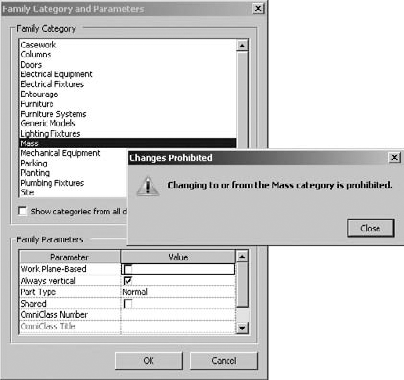
You won't be able to trick Revit by creating a generic model family and then convert it to a mass by changing the family category (Figure 9.128). But there's another way, so just hang in there!
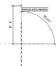
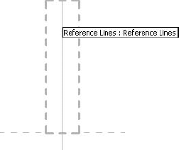
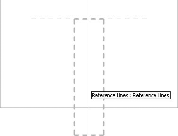
Go to a floor plan reference level view in your family. Begin by creating a reference line (not a reference plane), as shown in Figure 9.129. Note that the reference line is drawn from the intersection of the reference planes in an upward direction.
Draw another reference line in a downward direction (Figure 9.130). These reference lines will control the angular "twist" in our eventual family.
Now you're going to create a blend (Figure 9.131) that is associated with the reference lines you just created. The bottom of the blend will be associated with the first reference line and the top of the blend will be associated with the second reference line.
Before you start to sketch the bottom shape for the blend, it's important that you select the reference line as your work plane (Figure 9.132).
Select the upper reference line as shown in Figure 9.133.
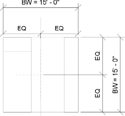
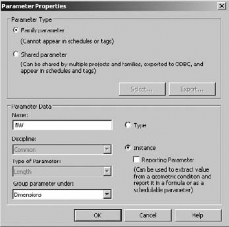
Sketch a rectilinear form as shown in Figure 9.134. The exact dimensions aren't important. What is important is that the dimensions are equally distributed between the reference lines. You also want to give parameters to the overall dimensions. We've called the instance parameter BW (for bottom width) and assigned the parameter to both the overall dimensions.
When you add the parameter, assign the settings shown in Figure 9.135.
Select Edit to sketch the top of the blend. But make sure that you set the bottom reference line as the work plane (Figure 9.136). This will allow you to control the angular twist of the blend when it's complete.
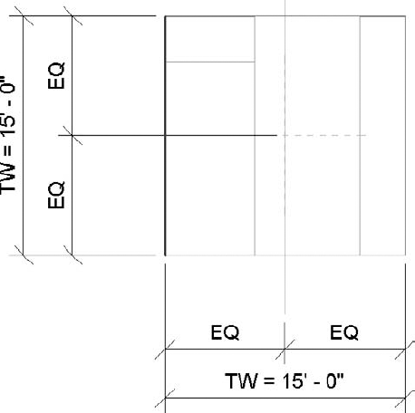
Essentially we're going to repeat the previous step for the lower sketch for this upper sketch. Equally distribute the overall dimensions and give the parameters as shown in Figure 9.137. We've called these parameters TW (for top width).
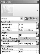
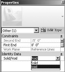
Now that the base and top width parameters have been set, you can add parameters to control the height of the blend. Do this by selecting the button to the right of the second end constraints (Figure 9.138).
Add the parameter H (for height), as shown in Figure 9.139. Now select Finish Family to complete the blended form.
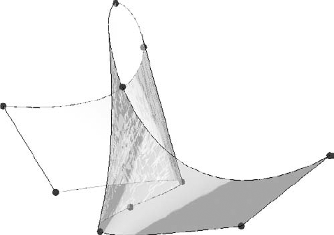
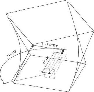
You should take a moment to test that the reference lines control the top and bottom sketch of the blend (Figure 9.140). Simply select the reference line to highlight it and then move the end of the reference line. The other end remains associated with the intersection of the insertion point and the top and bottom sketch rotate.
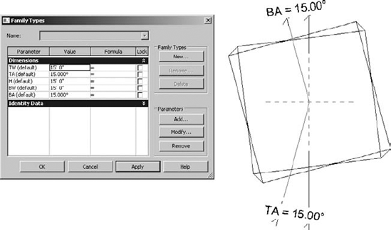
From a plan view, move the reference lines so that they're no longer on top of the reference planes. Now you can add angular dimensions between the reference line and the reference plane (Figure 9.141). Furthermore, you can add parameters to control the top and bottom angles of the blend. We've called these instance parameters BA and TA (for bottom angle and top angle, respectively). Figure 9.141 also shows all the parameters that control this blend. Go ahead and test them.
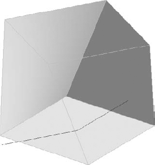
You're going to use the edges of this blend to drive the geometry that we're going to create. But since we don't want to see this blend, we'll turn it into a void (Figure 9.142).
After you change the solid blend into a void, it will look similar to Figure 9.143.
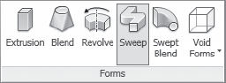
You'll begin to create the sweep that will create our building mass in the project environment. That's right—the building mass is going to be based on a circuitous sweep! Select the Sweep function from the Forms tab (Figure 9.144).
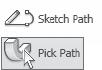
Now select Pick Path (not Sketch Path) in order to select the edges of the blend previously created (Figure 9.145).
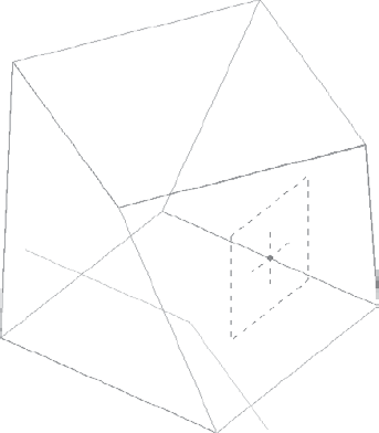
Pick the edges of the blend, as shown in Figure 9.146. Note the location of the sketch plane along the lower rear edge. This is because this is first edge selected.
Once you have selected the edges of the blend, click the Select Profile option and select Edit Profile (Figure 9.147). This will allow you to sketch the profile in direct context of the selected edges.
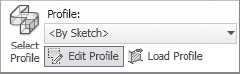
After you've sketched the profile as shown, be sure to add parameters to the profile width and height. We've called the instance parameters PW and PH, respectively (Figure 9.148).
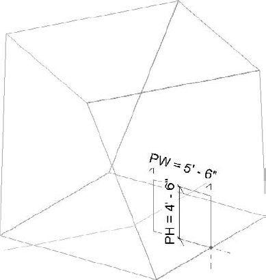
Finish the sketch and the sweep, and the profile will generate as shown in Figure 9.149.
Now it's going to start to get really interesting! We'll use this generic model family in the project environment and Revit will think it's a mass:
Open a new project and begin by creating an in-place mass. We've named the mass as shown in Figure 9.150.
While still in the In-Place Mass mode, go back to your family and load the generic model into your project environment. Go ahead and place the generic family as a component into your project. Again, this is being done during In-Place Mass mode.
Flex the parameters as shown in Figure 9.151. What started as a small parametric form the size of a room is now over 100' (30m) tall!
Now finish the in-place mass. Even though this is a generic model family, because you've placed it during In-Place Mass mode, Revit treats it as a mass.
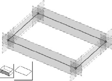
Add the levels as shown in Figure 9.152 so that there are levels that extend across the entire elevation of your massing.
Return to In-Place Mass mode and select the generic mass, and you'll be able to add floor area faces to your massing (Figure 9.153).
If you hover over the face and tab to select it, you'll also be able to associate patterns and pattern-based components with your generic massing family (Figure 9.154). This is because Revit is now treating it as a massing element in the Mass category.
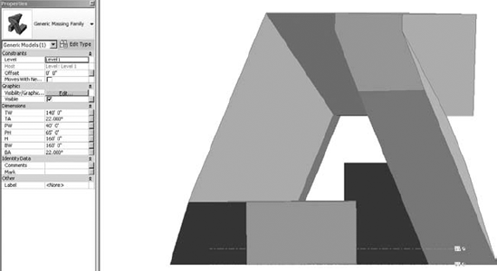
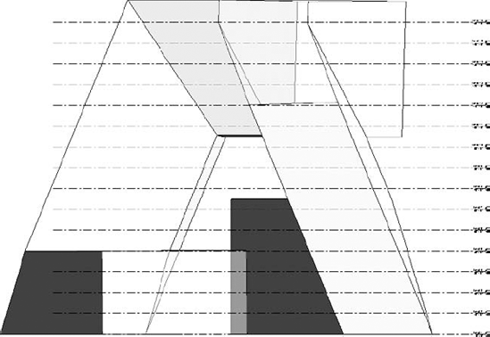
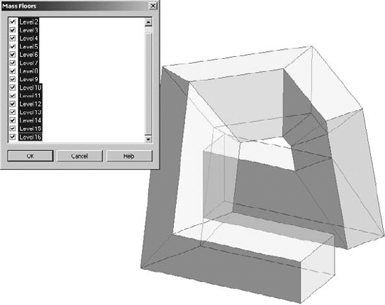
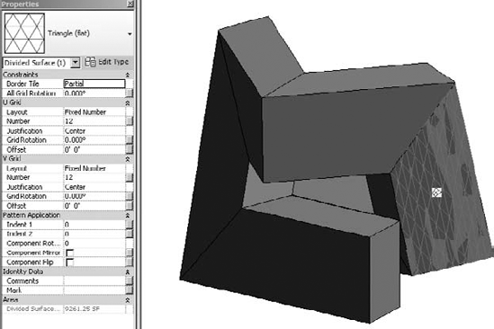
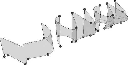
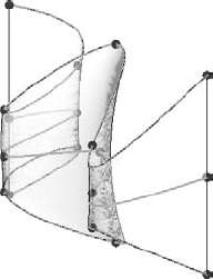
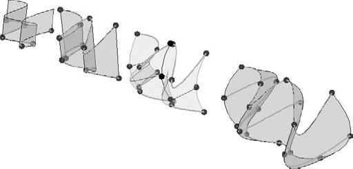
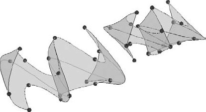
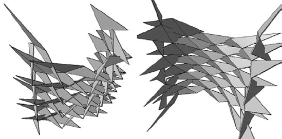
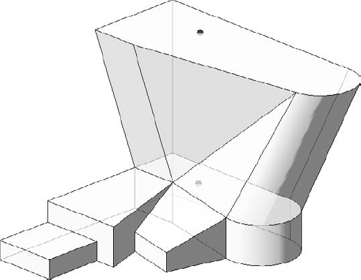
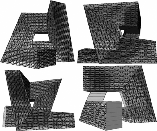
Figure 9.155 shows four perspective views of the completed massing study, all created with the familiar geometry toolset.
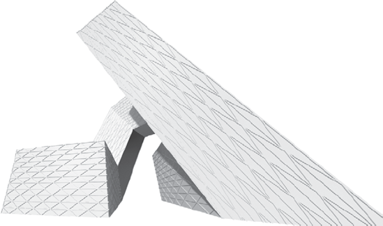
We've also rendered the model as shown in Figure 9.156. The results are quite interesting, and you'd still have the ability to modify the underlying parametric family and then rehost the faces. You'll also be able to schedule the volume, surface, and floor area of the mass.
You can download and further investigate the files that were used to create this exercise in the Chapter 9 folder. Simply download the project file c09_Parametric_Generic_Massing.rvt, which contains the in-place massing and the loaded generic element.
Now let's begin to investigate how to create parametric massing in the Family Editor using the conventional massing tools.
Let's start by opening a conceptual massing family template, as shown in Figure 9.157. You'll also turn off the gradient background in this section.
In the past, the ability to parametrically control objects in the massing editor was done using reference planes and reference lines. What was great is that Revit introduced reference point elements in 2010. Point elements allow for Cartesian x, y, z as well as rotational control.
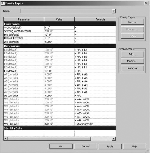
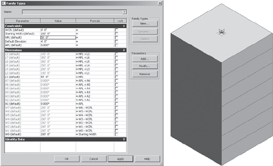
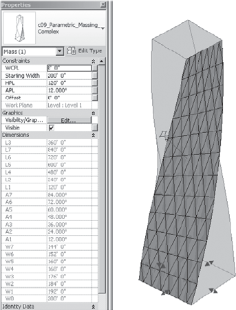
With all complex and parametrically controlled families, we think it's best to get the rules down first. In this case, the rules are the parameters and formulas that will control a twisting, tapering tower. Open the Family Types dialog box and enter the values and formulas shown in Figure 9.158. Doing this first will save a lot of time and frustration from having to name parameters. You'll only need to assign parameters as necessary.
We're going to create the first rectilinear form on the first reference level. As you do this, be sure to use reference (not model) lines (Figure 9.159).
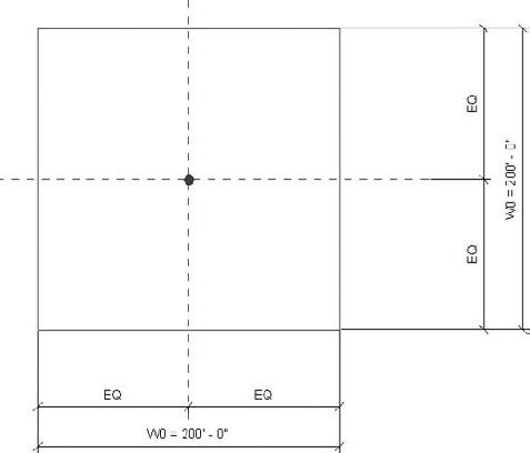
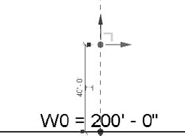
Dimension the sketch twice, making sure to use the EQ function to evenly distribute the sketch at the center of the reference lines at the origin. When finished, associate both overall dimensions with the W0 parameter that you've already created (Figure 9.160). W0 is shorthand for the width dimension on the 0 level.
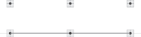
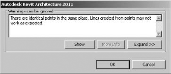
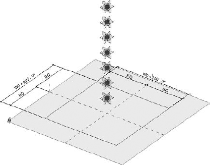
While in the same view, place seven point elements at the intersection of the default reference places. Each time you place a point element, you'll get a warning about overlapping point elements, as shown in Figure 9.161. Go ahead and ignore these warnings.
Now go to your south elevation and select just one of the point elements that you placed in plan. You can elevate it manually by dragging the up arrow to move it away from the other overlapping point elements (Figure 9.162).
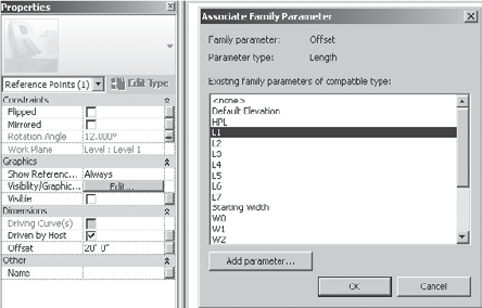
But when you select the arrow, you'll also have the option to parametrically associate the point element with one of the seven instance parameters that you've just created (Figure 9.163). The L parameters refer to the level number of each of your point elements. The first point element is L1 since it is reference level 1.
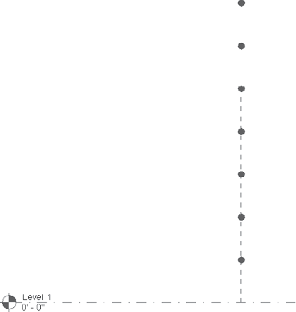
Now go ahead and do this for all your point elements. When you are finished, the south elevation will look similar to Figure 9.164.
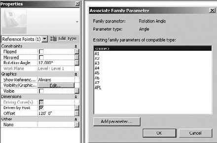
Right now the point elements are just spherical nodes. Their reference planes are not visible. Let's change that by selecting all of them and then selecting Always next to the Show Reference option in the Graphics panel of the Properties dialog box (Figure 9.165).
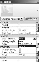
The reference planes of your point elements will now be visible, as shown in Figure 9.166.
Select the lowest point element and associate it with the parameter that will control its angular rotation (Figure 9.167). Select the button next to the rotation angle and associate it with the A1 instance parameter.
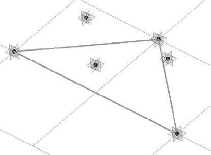
Now set the active work plane to the point element, as shown in Figure 9.168. Then sketch a rectilinear shape as shown. Dimension it just like we did for the sketch at level 0. Dimension both directions with an overall dimension as well as an EQ dimension. Finally, associate the overall dimensions with the W1 parameter, which will control the width of the sketch.
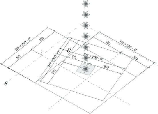
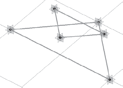
Systematically do this for each of the point elements, making sure to set the respective reference plane before you sketch the shape with reference lines. When you have finished this for all seven point elements that you created, your view will resemble Figure 9.169.
For clarity, we've hidden the dimensions in the view, so that you can see all the reference lines and point elements.
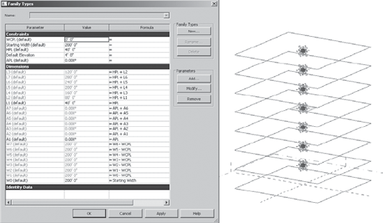
Now select all the reference lines and select Create Form. Although this will look like a simple extrusion, it's actually a blend with many profiles. Let's open the Family Types dialog box and begin to test the results before loading into the project (Figure 9.170).
Test the parameter that controls the distance between levels by increasing the HPL instance parameter (which stands for height per level).
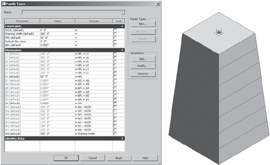
Now let's test the ability of the shape to taper (Figure 9.171). Do this by increasing the WCPL instance parameter (which stands for width control per level).
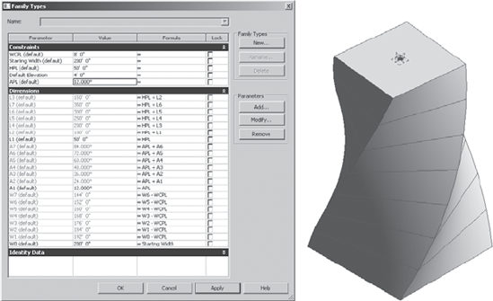
Now let's test the parameters that control the amount of angular twist per level (Figure 9.172). Do this by increasing the APL parameter (which stands for angle per level).
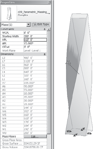
Now that we've tested the massing in the family environment, go ahead and open a new project and start to create a new, in-place mass. Then place this family into the project during In-Place Mass mode. When you select the massing family, you'll be given access to all of its parameters in the Properties dialog box, as shown in Figure 9.173. You can quickly and easily test the massing parameters in order to significantly increase the height, width, taper, and incremental rotation of the massing family.
Adding patterns to the face of your mass should be second nature if you've been doing all the exercises in this book. Simply tab to select the face, and then apply the pattern as shown in Figure 9.174.
Floor area faces are another simple matter. Provided you have enough levels in your project, simply select the mass and then select the levels that you want to associate with the floor faces (Figure 9.175).
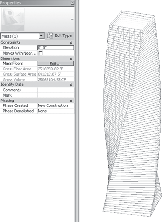
Creating interesting and complex massing studies that can be parametrically controlled isn't just a skill developed over time. The rules that you develop to make and reiterate your design are also carefully considered aesthetic choices to make decisions rather than blobs! To see this file, go to the Chapter 9 folder and download c09_Parametric_Massing_Complex_Project.rvt.
- Create and schedule massing studies.
Starting the design process with actual building elements can lead to a lot of unexpected frustration. Walls lead to rooms, which get room tags and eventually scheduled. But if you've failed to fulfill the program, you'll wonder where to start over!
- Master It
You're faced with creating some design studies of a large hospital complex. How would you go about creating a Revit project that would allow you to create a massing study and schedule it against the design program?
- Know when to use solid and surface masses.
While solid masses and surface masses can both be used to maintain relationships to host geometry like walls and roofs, surface masses can't be volumetrically scheduled or contain floor area faces.
- Master It
You've been asked to create a complex canopy system for the entry to a hotel project. The system will consist of a complex wave of triangular panels. What kind of mass would you create?
- Use mathematical formulas for massing.
Not all massing is going to be intuitive, in-the-moment decision making. By discovering the underlying rules that express a form, it is possible to create the formulas that can iterate and manipulate your massing study. So rather than manually manipulate the mass, you simply manipulate the formulas related to your mass.
- Master It
What's the best way to discover and create these formulas?