
The ability to design a building in the computer used to be a differentiator. Computers were expensive, applications were expensive, and the people who knew how to use those applications were often expensive specialists who would take other people's work and re-create it digitally.
But now, designing in the computer is a commodity; just about anyone can do it to a reasonable level of proficiency. What has changed?
Well, many projects go through stages and phases. As a result, it's necessary to distinguish the element of time in your project: how something exists, how it will change, and what it will look like when the project is complete. In addition, design is about maintaining relationships between repetitive elements. Sometimes this repetitive element could be a single component in your project, such as a light or a piece of furniture. But it could also be an entire collection of elements, such as a hotel or hospital room.
Finally, one digital design at a time isn't enough. You need to be able to see many ideas simultaneously and in context with other ideas. The client and contractor need to see options and alternates. And it's important that these options not be fully independent, separate files so that the results can be analyzed and compared to each other.
This chapter focuses on these three concepts: time, relationships, and iteration. In Revit, they're addressed with phasing, groups, and design options. In this chapter, you'll learn to:
The design of a project often goes through phases traditionally marked by level of detail and specificity. One of the earliest phases, schematic design, eventually evolves into construction documentation. This liner progression makes a lot of sense when drawings are discrete and moved through their own linear progression.
First plans, then elevations, then sections—each drawing relied on the information of the one that came before it and were often adjacent to each other on the same sheet of linen for faster reference.
Revit can be used much the same way as the traditional design processes described in the previous paragraph. But don't be surprised if you're quickly frustrated. The information gathered the first moment of design seems specific and fixed, having been automatically generated in a schedule that's just waiting to be immediately updated with an answer that isn't the one you were hoping to see.
Revit doesn't give you the benefit of working almost myopically focused on a particular task at a time and being accountable for only that task. Everything you do is influencing the entire project. If you're working on the plans, you're accountable for the elevations. If you're working on the sections, you're accountable for the schedules. And at first, understanding the holistic implications of your design decisions seems like too much information too soon—and results in circular errors from which you can't seem to escape.
Of course, the same thing happened in traditional 2D drawing and CAD environments. But by the time the circular conflict was discovered, the project was already in construction, and it was the challenge of the contractor to figure it out. And the designer often remained blissfully ignorant.
Revit will confront you with these design conflicts very, very quickly. One of the earliest marketing slogans for Revit was "If it's right anywhere, it's right everywhere." Well, the inverse was also true: if it was wrong anywhere, it was wrong everywhere. This is great on one hand because you're able to resolve design conflicts well in advance. But it's also a very unfamiliar way of working if you're not used to resolving design conflict so far in advance, because it interrupts your familiar design workflow.
We want to help you avoid these conflicts and roadblocks, or at least learn to be at peace with them until you're ready to address them. First, you need to stop thinking about Revit as a new tool to do an old thing. At first you can't avoid this. It's natural to see Revit through the patterns and principles of what you're familiar with in 2D and CAD. But it's not enough to see Revit as not being what it isn't. You need to start seeing it for what it is.
You need to embrace a new way of working that, for better or worse, allows you to approach design concurrently. This is not automatic, and it's going to take time, but you really don't have a choice. Working concurrently is simply not possible with the traditional, 2D CAD and task-centric tools. As hard as you might try, there's always something important that would be missed along the linear progression that those tools forced you to follow.
One of the biggest mistakes when trying to use Revit, a tool that allows you to work concurrently, is to expect it to conform to a design process that forces you to work linearly. And by the time you start working with phasing, groups, design options, and links, if you're still working in a linear mind-set but Revit is coming at you fast and furious with unexpected and completely concurrent information, you'll feel almost paralyzed.
If the old 2D CAD process was a linear progression of predesign, schematic design, design development, and construction documentation that all the while was intent on resolving plan, elevation, section, and detail, what's the new Revit process? Well, it's also in two parts:
Instead of Pre-Design, Schematic Design, Design Development, to Construction Documentation, you're going to think along the lines of restrictions, relationships, repetition, and representations. You can't think about predesign in Revit. You need discover what you should and shouldn't do. Restrictions are not limiting—they're freeing! Once you resolve your restrictions, you'll know where to focus. You can't think about schematic design in Revit. You need to think about the core relationships that you're trying to create and maintain. You can't think about design development. You need to think about the repetition of an idea and a theme and how the repetition will need to flex when it encounters a unique condition. And you can't think about construction documentation. You need to think about the representations of your project that communicate far more than 2D information.
Instead of plans, elevations, sections, and details, you need to think along the lines of intent to content. A wall is not a thing in a plan. It's an idea that exists everywhere. It's got intent, and the same goes for floors, furniture, lighting, and curtain walls. You don't know exactly what they are, but you understand the intent of what they are.
So get the idea of a wall as something in plan or elevation or section out of your mind and think about the "wallness." You don't know what it's made from (yet), but you do have a fairly good idea about what it's supposed to do and about where it is. Later, the intent of your design will evolve into specific content. The wall will have structure, finishes, and performance requirements.
The same goes for the other elements in your building. The intent of what they are and where they are will give way to manufactured specific content. And this content will maintain the intent of your design to locate and resolve your design intent far beyond the traditional resolution of a 2D detail. This specific content will have energy requirements, give off heat, be made of sustainable materials (or not), and so on. How can all this information possibly be contained in a traditional detail? It can't!
So, stop using Revit to do an old thing, and embrace the future of meaningful and concurrent information. As a designer, you owe it to your contractor, your owner, and your future!
Phasing is Revit's method of allowing you to add the element of time to objects in your project. It's easy to think of an architectural design in terms of what something is, where something is, and how it will be assembled. Phasing adds the dimension of "when" something is, which is incredibly useful and powerful.
Phases are most useful for doing the kinds of tasks that require you to show when elements are being introduced into your design. But a few words of caution and clarification: we don't recommend using extensive phasing to simulate construction sequencing, or "4D." It might seem like a great idea at first, but ultimately it'll break your model and lead to a lot of confusion across your project team.
The reason is threefold. First, using phasing to illustrate construction sequencing will not allow you to use phasing for its intended use. So if you need to show stages of existing, demolition, new construction, and so on, you'll find yourself having to work around sequences of Week 1, Week 2, Week 3, and so on. You will have traded more functionality in one area for limited functionality in another area.
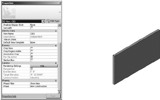
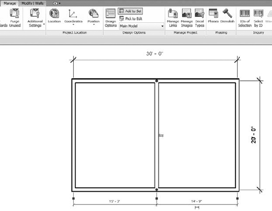
The second reason is that it will break connections between elements that are normally joined. For example, in Figure 11.1, two walls intersect that belong to the same phase. The fact that they are graphically and geometrically joined is the desired condition.

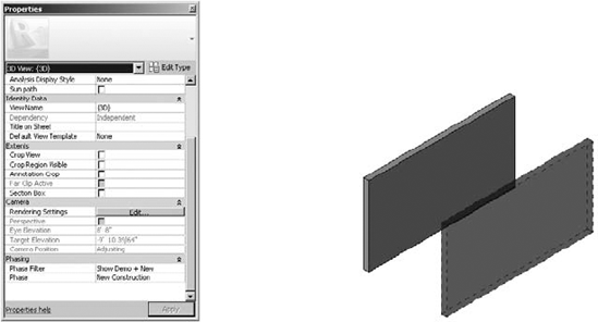
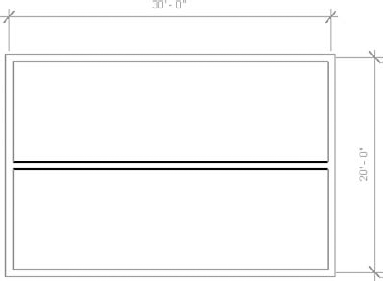
But when walls are not from the same phase, their join condition may not clean up as intended, as shown in Figure 11.2. This can create a lot of tedious cleanup that isn't the best use of your time.

Finally, the best reason not to use phasing as a construction sequencing tool is that there's a better way! It will allow elements of various sequence properties to be scheduled, viewed, and even color-coded based on the sequence value that you define.
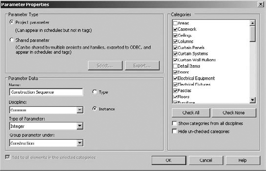
By using project parameters, you're able to create and assign an instance parameter value to everything in your project that you'd want to assign a construction sequence, as shown in Figure 11.3.
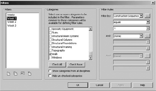
Once you've created this instance parameter, you'll be able to create view filters and filter rules that override the default condition of an object based on your parameter, as shown in Figure 11.4. Each Construction Week value is being given its own rule.
Combined with Visibility and Graphic Overrides, you're able to create a filter that modifies the graphics based on a parameter, as shown in Figure 11.5.

The result is being able to modify the graphics of a view to illustrate some metadata about the objects in a far more flexible and predictable way than mere phasing, as shown in Figure 11.6. The other benefit is that this technique is not limited to views of geometry. View filters can be applied to any view, including schedules, which will allow you to group and filter schedules based on your unique project parameter.
Now that you understand a better way to create sequencing in Revit using parameters and filters, we'll discuss how phasing is used.

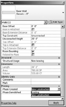
At a high level, only three types of elements can be associated with a phase in Revit: geometry, rooms, and views. Geometry is anything that you would use to build your design, like host components such as walls, floors, ceilings, and so on, as well as family components such as doors, windows, furniture, lighting, and so on. Once an element is placed in the project, the phase may be changed, as shown in Figure 11.7.
Rooms are also given phase properties, but there is an important difference: the phase of a building geometry may be changed after placement. The phase of a room may not, as shown in Figure 11.8. If you want to change the phase of a room, you'll need to delete and re-create it in the proper phase. You'll also find it faster to press Ctrl+X to cut the rooms from one view and then press Ctrl+V to paste them into a view of the desired phase.

The phase of an element when initially placed is often confusing to a new user, but it's quite simple: the phase of the view that you're placing the element into determines its phase, as shown in Figure 11.9. Again, this is not as critical for geometry, since the phase of a building element can be changed after placement. But there are occasions when you're placing a lot of elements that you intend to be in a particular phase, and you'll want to create a view with that phase as active. Then you can place the elements in that view and not worry about having to change them later.
However, a view's phase is critical when you're placing rooms since you can't modify the phase of a room after placement. So be sure to verify the phase of the view before placing rooms.

Let's get into the details of phase settings. Once you understand what each of the dialog boxes do (as well as what they don't do), the rest of phasing becomes clear.
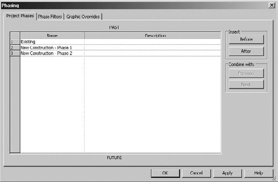
On the Manage tab, click the Phases button, which will open the Phases dialog box, as shown in Figure 11.10. You'll notice that there are three tabs. The first tab is for your project phases.
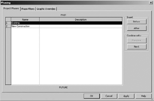
Right away, this is where people get confused, because they think that they need a phase for every different view that they'll be creating. And in the most common of phased projects, you'll have views to illustrate Existing, Demolition, and Proposed conditions. But since this dialog box only shows Existing and New Construction, people will in error create a new phase for Demolition.
If your project is a simple, three-phase kind of project (like a tenant upfit showing three phases), this extra phase isn't necessary. Just trust us! Basically, the Project Phase tab is for determining when the geometry is being created (not demolished). When would you want to create more phases? When you need to create geometry in more than these two phases.
For example, think of a staged construction project that will happen in two new phases. In this scenario, you need to move an entire office floor to one side of the building—all the staff, furniture, and so on. While everyone is working in half the building, you begin to design a phase that demolishes the other half and begins to reconfigure the proposed floor layout. This might be "New Construction – Phase 1."
Once that phase is complete and everything is cleaned up, you move everyone into the new space, and start the same process on the other half of the building. This phase might be "New Construction – Phase 2." Do you notice that we're still not creating a Demolition phase? Again, that's because the Project phases allow you to set when geometry is being created—not demolished.
Go ahead and create the two phases as just described (see Figure 11.11). We'll use this in a sample exercise in a moment.
Once you've created these additional Project phases, pick any project geometry and look at its instance parameters. You'll notice that it can be assigned to any one of these three phases, as shown in Figure 11.12.
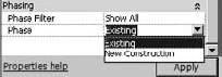
The next tab in your phasing dialog box is Phase Filters (Figure 11.13). There's seven predefined phases shown. All these phases can be deleted except for the Show All option.


Don't be concerned if the filter names seem a bit cryptic at first. What's really important is the four graphic conditions that can be overridden: New, Existing, Demolished, and Temporary. Concentrate on these views for the moment, and the filter names will begin to make sense.
Select any of the drop-downs, as shown in Figure 11.14. You'll notice that the phase filter can override the graphics in one of three ways:
The object can be shown by its category settings or not overridden. It will display in the project just like it does by default.
The object can be overridden. That means that you can define a graphic override for that object. We'll get into the Graphic Overrides in a moment.
The object can simply not be displayed.
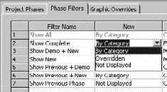
Once you understand how each of the phase filters displays objects, it all begins to make sense. For example, the Show Complete phase filter shows New and Existing elements by Category. But Existing and Temporary elements are not displayed at all. If you want to show the project when in the finished condition, when the dust has settled and everything is complete, this setting makes sense.
So to recap, things can be shown, not shown, or shown differently. Easy!
If there's any remaining confusion, it probably involves the naming convention of Show Previous + Demo. A better name might be Show Existing + Demolition but Existing is a bit misleading because this setting is showing the previous phase, which is not necessarily existing elements. It might be Temporary elements that need to be demolished. Therefore, Show Previous makes more sense.
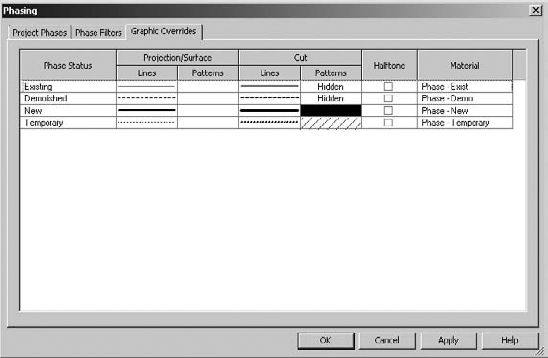
The Graphic Overrides tab is the final tab in the Phasing dialog box (Figure 11.15). This dialog box relates back to the "Overridden" assignment of the previous tab.

This dialog box allows you to override geometry in a few areas; the Line and Pattern characteristics of Projection/Surface and when Cut. You also have an option to just halftone the element. And finally, you can assign a unique Material setting when rendering. While this is helpful for illustrating actual rendering phase information, it can also be useful for rendering everything to a matte material, something we discuss in Chapter 15.
Now, if there's anything confusing about this dialog box, it's the lack of the ability to create a graphic override for "Future" elements. Such a feature would be helpful for showing future context in a phased construction, when you're trying to visualize the next condition. But as it is, phasing can show you where you are and where you're coming from, but not where you're going.
Why there's no Future phase in Revit is confusing to us; we hope to see this addressed in a future version.
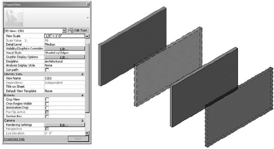
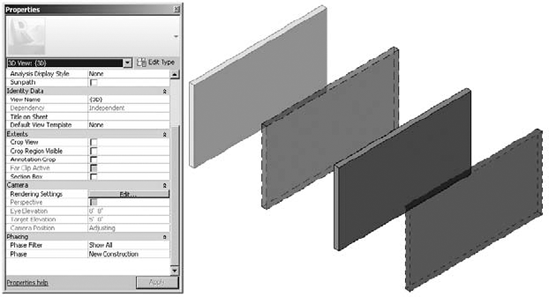
Here's a simple exercise to illustrate each of the phases in a single view. First, open a new project using a default template. Next, draw four walls in parallel and then open a 3D view (Figure 11.16).

By default, all of these walls have been created in the New Construction phase because the phase of the view is New Construction.
Now, selecting each of the walls, associate them with each of the following phase settings:
Wall 1: Phase Created: Existing / Phase Demolished: None
Wall 2: Phase Created: Existing / Phase Demolished: New Construction
Wall 3: Phase Created: New Construction / Phase Demolished: New Construction
Wall 4: Phase Created: New Construction / Phase Demolished: New Construction
Figure 11.17 shows what you'll have when you're finished.
Right away you'll notice that the Existing (not Demolished) and the Proposed (not Demolished) look similar, except for the edge color. This isn't enough. So let's change the graphic properties of this wall so it's graphically more distinct.
Go to the Manage panel and select Phases; then click the Graphic Overrides tab (Figure 11.18).
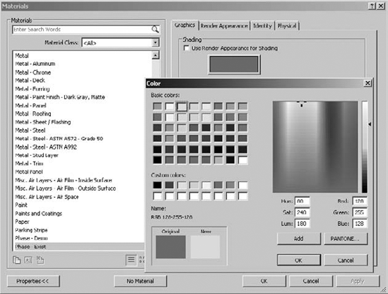
Next, select the option to open the Material setting for the Phase-Exist material (Figure 11.19).

This is the setting we want to change. Select the Shading option, and you'll be able to assign a different shading value. We're selecting the lime greenish color along the top row (Figure 11.20).
When you finish changing these settings, you'll have the result shown in Figure 11.21.

Now you can really graphically tell the phases apart. We think this particular setting should be part of the default Revit template. That way, new users would be able to distinguish the phase of an object far more clearly than in the default template.
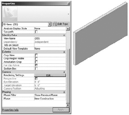
Now that we've talked about the phase properties of geometry, we'll cover the phase properties of views. Starting with the view from the previous example, select the View Properties. Selecting the space of the view, and then notice that the Properties dialog box automatically changes to reflect the properties of the view (Figure 11.22).
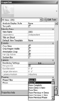
Applying each of these filters will help you understand the implications of how this will affect the properties of what will be shown in a view and how it will be shown.
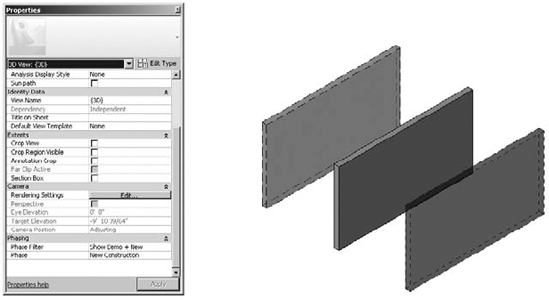
First, let's start by changing the phase to New Construction and set the phase filter to Show All (Figure 11.23). This will show all the elements and override their graphic based on their construction phase and whether they're demolished. And it gives us a sense of all the elements as they exist in time.
And although this is great for 3D views, where every phase has a distinct color, it's also wonderful for working in a plan, elevation, or section. Simply shade the view while working and you'll be able to clearly distinguish between objects in different phases, as shown in Figure 11.24.

Now let's start moving through each of the sequences. But here's the important part. Rather than sequentially moving through the various phase filters from top to bottom, let's move through a sequence that makes sequential sense.
Let's begin by keeping the phase filter to Show All, but setting the phase back to Existing (Figure 11.25). This will only show the object created in the Existing phase—and their graphics are not overridden.

Keep in mind that it's impossible to see anything that's proposed from this present Existing phase. That's because there's no way to see beyond the present phase. We think you should be able to do this, but Revit just doesn't offer that functionality yet.
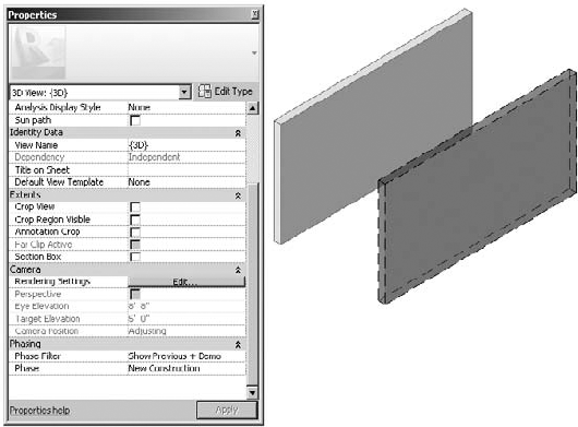
Now you need to set the phase to New Construction and select the Show Previous + Demo option (Figure 11.26). This shows both existing walls (the walls from the previous phase). And one of the walls is clearly being demolished. What's important to remember is that the graphic overrides that are being applied are relative to what you'd be seeing through the lens of the New Construction phase.
Now let's select the Show Previous Phase option in the phase filter, as shown in Figure 11.27. Maybe a better name would be Show Existing To Remain because the demolished elements are no longer shown.
Now we'll move forward another moment in time and set the phase filter to Show Previous + New. This will show only the remaining elements (not any of the demolished content) from the present and previous view (Figure 11.28).

This brings up another interesting point. Why not show the Existing To Remain as well as the Proposed and Proposed Temporary elements? Although you could also create a new phase filter, for this example, we'll change the settings of the Show Previous + New Graphic override settings (Figure 11.29).
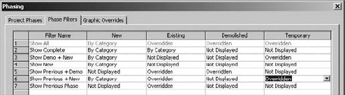
Figure 11.30 shows the result.

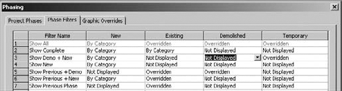
The next order of sequence will be to set the view to Show Demo + New, which would show demolished elements from the present and previous phase as well as any New elements from the present phase (see Figure 11.31).
But this brings up another interesting point. If you want to show only the objects in the present phase (as well as demolition), then you'll want to modify the phase filters in the Phase Settings, as shown in Figure 11.32. We don't know how common it is to show demolition from a previous phase without showing the existing from the same phase. That's why we're just changing an existing setting rather than creating a new phase filter.
The result would be only the New and Temporary elements being shown in this view (Figure 11.33).
The next sequence, Show New, will only show the New elements in the present phase (Figure 11.34).
Now comes the final setting, Show Complete (see Figure 11.35). This only shows the existing elements that remain from the previous phase (after demolition) and the new elements that are being proposed (minus the temporary construction that has also been demolished).

You can find the example file used in this section, called c11_Phases.rvt, in the Chapter 11 folder.
It's easy to think of groups kind of like blocks (if you have an AutoCAD background) or cells (if you have a MicroStation background). But groups are much more than this. Yes, they're great at maintaining repetition within your Revit project. But there are some major differences:
Creating groups is quite easy. And whether it's a 2D or 3D group, the insertion point for the group is easily defined and modified. The same can't be said of simple 2D blocks.
Updating groups is a breeze. It's easy and intuitive to modify a group after it's been created. Practically anyone on your team can do it, which means that design workflow will not bottleneck in your project team.
Copying groups throughout your project is also a breeze. Groups can be copied across different levels, rotated, and even mirrored (although mirroring isn't such a good idea, but more on that later).
There are a few good practices that you'll want to keep in mind when using groups. But they're so straightforward that you'll wonder how you've ever worked without them.
You can create two kinds of groups in Revit. One is just for geometry, and they're called model groups. The other is just for view-specific content like text, tags, dimensions, and so on, and they're called detail groups. You can create one kind of group or the other explicitly. But if you try to create a group with both model and detail elements, Revit is smart enough to create a detail group that's associated with the model group.
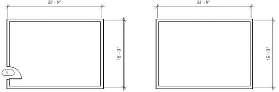
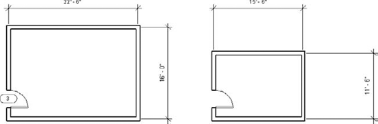
To demonstrate this, open a new project and start with drawing four walls, as shown in Figure 11.36. Don't forget to dimension the length and width conditions.

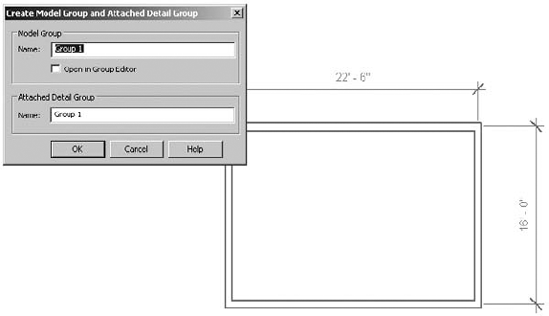
Now select the Create Group function under the Modify | Multiselect tab. Go ahead and keep the default name Group 1 for both Model Group and Attached Detail Group (Figure 11.37).
Now select the group and copy it to the side of your original group. You'll notice that only the geometry is copied, which is fine (Figure 11.38).
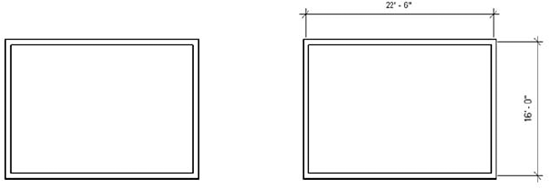
Associating the detail group is really simple. Just select the group and then select the Attached Detail Groups option, and you'll see the dialog box shown in Figure 11.39.

The results are fairly straightforward (Figure 11.40). Both groups are now identical with geometry and dimensions.

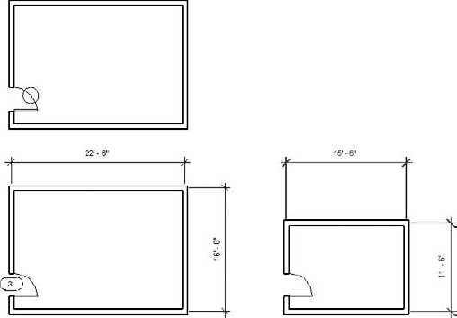
Now that you've created two identical groups, you'll add a door to one of the walls that belong to the group, as shown in Figure 11.41. But don't add it to the group—just place it in one of the walls.
Now you can select the group to the left and select Edit Group. You'll enter a special editing environment, as shown in Figure 11.42. Everything in the view becomes a sepia tone and you're able to add, remove, and attach other elements to your group.

Now add the door to the group by selecting the Add function. You'll notice that you can't add the door numbers. This is fine, because you'll add them later when numbering. Now finish the group and you'll notice that both groups have a door in the same location (Figure 11.43).

The process is essentially the same for modifying groups: enter Group mode, make the changes and/or additions, and then finish the group. Be careful when you're duplicating and swapping one group for another one, which is common during design iteration.
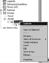
First, duplicate the group. The easiest way to do this is to right-click the group name that you want to duplicate in the Project Browser, as shown in Figure 11.44.
Now you can select any of your groups and swap it for this new group. Go ahead and exchange Group 1 for Group 2.
Now enter Group Edit mode for this second group, and edit it as shown in Figure 11.45; then finish the group.
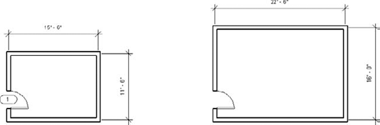
This brings up an important point of discussion. Groups have insertion points that need to be considered before you exchange one group for another. When you create a group in Revit, the insertion point is initially at the geometric center of all the stuff in the group, which is fine if you're trying to find it.
But keep in mind that as you edit the group, the insertion Apoint doesn't move until you deliberately move it. This can be seen in Figure 11.46, as editing the geometry for Group 2 retains the same insertion point that was active when the group was created.

Moving the insertion point is an easy matter of dragging (and if necessary, rotating) the Insertion Point icon to a common location before swapping one group for another (Figure 11.47).
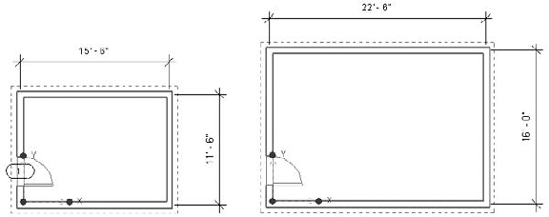
Once you've done this, swapping groups occurs at the same relative location. Figure 11.48 illustrates Group 1 being swapped for Group 2, and vice versa. But common insertion points are being maintained.
Of course there will be occasions where everything in a group works great. And it works throughout the project, except for that one particular condition. This is really frustrating. And in the past, you had to create new groups for each slight exception, which might have been conceptually consistent, but often led to an exponentially growing list of group variants.
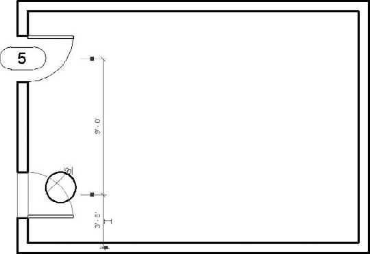
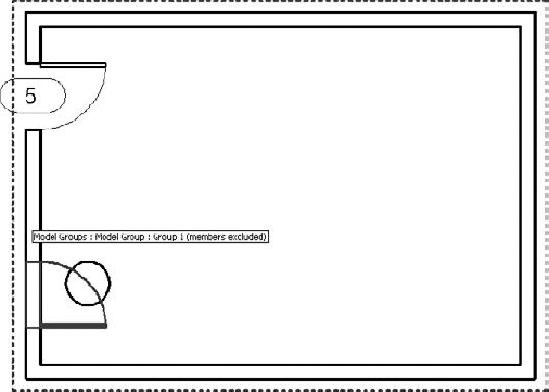
This is now deftly handled by excluding elements from groups. The rest of the groups are intact, and scheduling is aware of excluded elements. Figure 11.49 shows an example. We've copied the group above the first one. But in this condition, there's a column right in the middle of the door.
First, select the door and select Create Similar to place a new door where you want it to go. This door will not be part of the group (you can't place elements as exceptions). In this case, the new door has been placed above the grouped door, and its swing direction has been flipped (Figure 11.50).

Now you can exclude the door that conflicts with the column as an exception to the rest of all the other groups. This can be a bit confusing at first, because you don't enter Group Edit mode to exclude members from groups. Simply hover over the group and tab through until the door is highlighted. Then select the door, as shown in Figure 11.51.
Once this is done, you'll notice an icon to the upper left of the door (Figure 11.52).
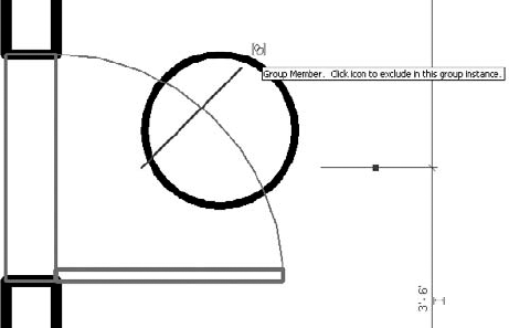
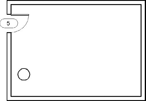
Selecting this icon will allow you to exclude the door as an exception to the group, and the wall will heal itself as if the door is not there (Figure 11.53).
Hovering your mouse over the group will reveal any hidden elements in the group (Figure 11.54). Just tab through to select the hidden door to include the component back into the group.
Even though we consider Revit to be the only whole building BIM (WBB) application in the world (by integrating the building, content, documentation, and multiuser workflow into one database), there are times when you'll want to share the data across many files.
And just like you wouldn't want your family components locked up inside a project file, there are good reasons to keep commonly used groups outside your project. You might even want to keep them in a folder just like your custom content. This can be accomplished by saving groups outside your projects.
Saving groups is a simple matter of right-clicking the group name in your Project Browser and selecting Save Group (Figure 11.55).
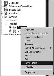
You'll then be prompted to save the group as an RVT file (not an RVG file as in the past). You can open this file like any other RVT file and then reload the group into the project in order to update all the instances.
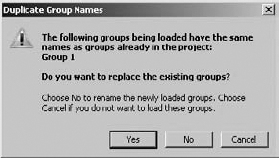
Be aware that when you load the group in a project, if the group name already exists, you'll be given a warning. You can overwrite the existing group (by selecting Yes) or load with the option to rename the group that's being loaded (by selecting No). Or you can cancel the operation altogether (Figure 11.56).
What's really great is that when you reload the group Revit even remembers to exclude previously excluded elements from the group that's been modified in another session of Revit. Figure 11.57 shows a desk and chair have been added to the group. The group has been reloaded, overwriting the original group, but the exclusion remains intact.
Because groups are also RVT files, they can be linked into the project environment as well. While you can't edit a link in place (as with a group), there's some excellent reasons you might want to start a group as a link and then bind the link at a later time, which will convert it to a group. Groups and links can also exist within design options (more on design options in a moment).
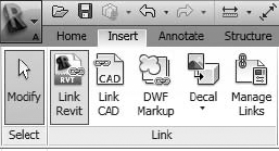
Simply select Link Revit from the Insert tab (Figure 11.58).
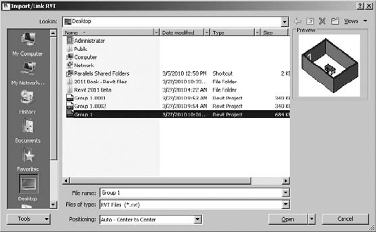
Then browse to your group and click Open, as shown in Figure 11.59.
After the link has been placed, you can copy it throughout your project. Keep in mind that all the functionality between groups and nongrouped elements will not behave the same as links and the rest of your project. For example, in Figure 11.60, the upper-right collection of walls and furniture is a link, not a group. And as a result, walls are not cleaning up between links and groups in the same way as they are between groups and groups or other walls.
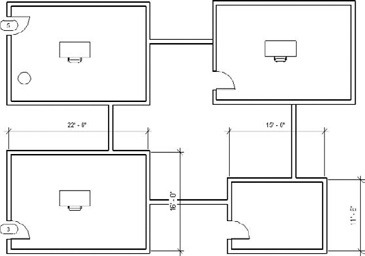
But this graphic restriction may not be a concern during programming and predesign, when links allow for a lot of rapid flexibility.
After you've resolved your design using links, you can bind them into the project environment (Figure 11.61).

But rather than "explode" the link into separate and unrelated elements, Revit converts the link to a group. Once this happens, the previous graphic issue is resolved as walls easily join across groups, as shown in Figure 11.62.
Groups are great for creating and maintaining design iteration within a single project. And they're also great for maintaining consistency across multiple projects, since groups can be saved and loaded across multiple files. They can even be linked as separate RVT files and then converted to groups at a later time.
But like everything in Revit (and in life), there are some important exceptions that you want to be aware of. Nearly every time there's been a problem with groups we've noticed that it's the result of doing one of the following five things. Not that doing any of these things will kill your project—they may be completely technically feasible. But they may put your project into a world of hurt that you'll wish you could have avoided:
- Avoid putting datum in your group.
You should avoid putting datum (levels and grids) inside your group. First, you can't manage the extents of the datum unless you're in Group Edit mode, which can create conflicts elsewhere in your project. Of course you will have the option to not include the datum when you bind your link. Again, this doesn't necessarily create a technical hurdle. But it can create a lot of confusion. We've seen situations where duplicate levels are deleted, only to find out that those levels were hosting content in the project.
- Don't nest groups.
You should take care to avoid nesting groups. Although nesting can save time in some situations when the design is preliminary and your team is trying to distribute content and design ideas quickly, you'll likely find a point of diminishing returns as the design evolves. You can't get to all the features and functionality of Revit when you're in Group Edit mode. And if you're nested deep into groups and trying to modify project properties, you'll get quickly frustrated digging in, out, and across nested groups to go back and forth between your group and project.
- Group hosted elements and their hosts together.
You want to keep your hosted elements and hosts together. For example, try not to group doors and windows without their host walls. Technically, nothing keeps you from creating a group from windows without their host. But if any of your windows become unhosted and then deleted, this will delete other windows that are properly hosted. This also goes to the heart of what needs to be hosted in a Revit project. Another example is that elements such as plumbing fixtures that don't need to cut their host shouldn't be hosted. Instead, they should be face-based (or assigned the option Moves With Nearby).
- Don't use attached relationships in groups.
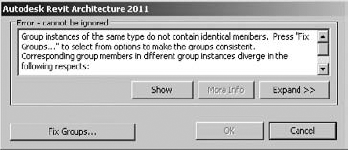
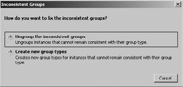
Avoid attached relationships within groups. In other words, give walls explicit heights rather than Attaching Top/Bottom to levels or other hosts (like floors and roofs). If you manipulate the datum or attached host and the relationship creates inconsistent conditions, you'll get a warning asking you to fix the groups (Figure 11.63).
Fixing the group really doesn't fix the group. It actually explodes it or creates a new group (Figure 11.64).
- Don't mirror groups.
Finally, and maybe most importantly: don't mirror groups. Instead, it's better to create left and right versions. Does mirroring work in concept? Yes. Does it work in the real world? Not really. Sorry.
Think about it. You'd love to be able to mirror that precious prototype coffee shop, right? Well, Revit doesn't disallow mirroring of content as a parameter (which still wouldn't solve the problem, but that's another matter). Mirror the coffee shop and now the baristas are foaming milk on the right rather than the left. This might look great in a rendering, but it doesn't make sense for the company that manufactures espresso machines.
And now the display cases have power supplies on the wrong side. The cash register has keys on the wrong side. The desk in the managers' office now has drawers on the left and filing cabinets on the right. And to make matters worse, the sink in the bathroom now has hot water coming from the wrong faucet. Again, it makes all the conceptual sense in the world to be able to mirror a building...and a group. But the implementation of trying to make this work can cost a lot of time and money trying to repair. And that's just a coffee shop. If you think it's a good idea to mirror a hospital room or a surgical theater or some other mission-critical building or civil construct, well...someone could die. Or you will have to work very, very late.
If you'd like to download the file that has been created during the examples, you can find it in the Chapter 11 folder; it's called c11_Groups.rvt.
Design options are great when you work within the rules of how design options work. It's kind of like the rules with mirroring groups. What you think might make sense conceptually doesn't always work in the practice.
Design options are great for iteration within the walls of a building or a single Revit project. Interior renovations can go off without a problem. Iteration of spaces or functions within well-defined boundaries is also not a problem.
But one of the first and most important rules to remember is that an object that is being hosted can't be in a design option unless the host is also in the design option (Figure 11.65). That means if you want to show a door in two possible locations as an option in your design, you'll have to create two walls to host those two doors in your two options.

Second, design options are not for "whole building" iteration. If you're not sure about which direction your big design idea is headed, don't put both buildings in the same file and think you're going to save yourself any time. You'll be better off starting another file (and if necessary, starting another file). Even if you're trying to resolve just a big part of a bigger building, put that big part of the building in a separate file and link the results. You can even put each of the links in their own design option. For example, if you have a couple of different ideas for your curtain wall, put that part of the design in a separate file and link them all into your main project file, assigning each of the links to a different design option.
With those two suggestions out of the way, we'll show you how to use design options as intended.
Again, let's start simple, establish the principle, and then add complexity later. Create four simple walls with a wall down the middle of the space both as shown in Figure 11.66.

We're going to configure this simple space into a design option that divides the space vertically in one option and horizontally in the other:
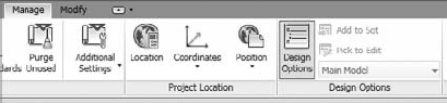
Select your Manage tab in order to initiate design options. Select the Design Options tab (Figure 11.67).
Create a new option set (which will automatically create one design option) and then create another option as shown in Figure 11.68. Click Close to dismiss the dialog box.
Now that you've started design options, everything in the project (which, admittedly isn't a lot) is now in the Main Model. Let's start adding elements to one of the two options.
In a process that might at first to appear to be a bit confusing, select the center vertical wall and add it to Option Set 1/Option 1 (Figure 11.69).
You'll do this by selecting the wall, which you notice will immediately initiate the Modify | Walls tab. But you can get around this limitation by simply and easily reselecting the Manage tab (that was just visible a moment ago before you selected the middle wall). Now select the Add To Set option and add the wall to the first option but not the second one, as shown in Figure 11.70.


Just as a side note, you'll need to do this every time you select elements in the Main Model and you need to add to a design option. But you'll get used to this convoluted and time-consuming process over time. You could create a keyboard shortcut or menu item to the Quick Access toolbar. But of course this would defeat the purpose of using the new user interface.
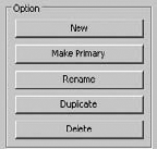
You can also add elements to a specific design option by selecting the option from the Design Options panel (Figure 11.71).

Another, faster option is to use the Active Design Option selector at the bottom of the screen (Figure 11.72).

This will allow you to enter a special mode where you can add elements from outside the option, or create them from within the option. Everything that is not inside this option will turn light gray, indicating that it is not inside the presently editable option. Now you can add another wall as shown (Figure 11.73).
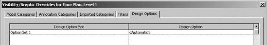
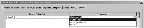
You notice that whenever you switch between Option 1 and Option 2, the view automatically changes to show the option that you've selected. This is because initiating design options automatically creates another tab in the Visibility/Graphic Overrides dialog box. By default, the Design Options tab shows Automatic (Figure 11.74). This means that the primary design option (in this case, Option Set 1) will be shown in the view.
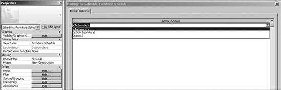
This tab is available for any view, even for schedules, as shown in Figure 11.75. Selecting the Visibility Graphics settings in the View Properties of a schedule filters the schedule according to the desired design option.
Of course, if you want to specify or lock a view to a particular design option, simply specify this in the Visibility/Graphic Overrides dialog box (Figure 11.76).
This can be particularly useful for views that are being placed on sheets. For working views, it's fine to leave the View Properties set to Automatic, so the view switches to actively show the desired design option.
As your project grows and begins to resolve more detail, it may be necessary to delete an option set, accept the primary design option, or delete a single design option. While some of these options might at create somewhat similar outcomes, there are important differences.
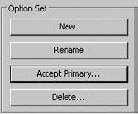
First, deleting an option deletes the option set and all of its associated options. You delete an option set by selecting it in the Design Options dialog box and clicking the Delete button (Figure 11.77).
You'll see the following warning indicating that you're about to delete all the geometry associated with the option set (Figure 11.78). Click Yes.

Additionally, any views that are associated with the option set will be deleted by default, but you're given the option to uncheck views that you want to retain, as shown in Figure 11.79.

Yes, this is a lot of warnings, but for good reason! All your related geometry, plans, elevations, sections, schedules, 3D views, and so on are about to be deleted. You do have the option to keep the views, but they'll only show what's left in the Main Model. And the Main Model may or may not technically exist. That's because if you only have one option set in your project, then design options will no longer exist. There's no longer a distinction between the Main Model and anything else.
Second, accepting the primary design option ultimately removes the option set, but it also retains the geometry associated with the primary option, as shown in Figure 11.80.

You do this by selecting the desired option set and then clicking the Accept Primary button in the Design Options dialog box. Accepting the primary option also deletes any of the other options associated with the option set. And finally, the design option set is removed and all and all of the geometry associated with the primary option is moved into the Main Model.
Finally, you can delete a single design option within an option set. However, you may not delete a primary option. You'll first have to assign a new primary option. Do this by selecting the desired option and then clicking the Make Primary button, as shown in Figure 11.81. Once this is done you can delete the formerly Primary Option.
Just remember that all of the previous warnings will apply. Deleting a design option will delete all the geometry and associated views.

Now it's time to bring it all together—phasing, groups, and design options. Let's create a tenant upfit in two phases. The first phase will resolve construction on one side of the space, and then we'll turn to the other side of the space to complete the renovation. We'll also rely on groups for collections of components. Finally, we'll create a design option for the second space. Ultimately, you need to visualize the exercise in plan, perspective, and schedule.
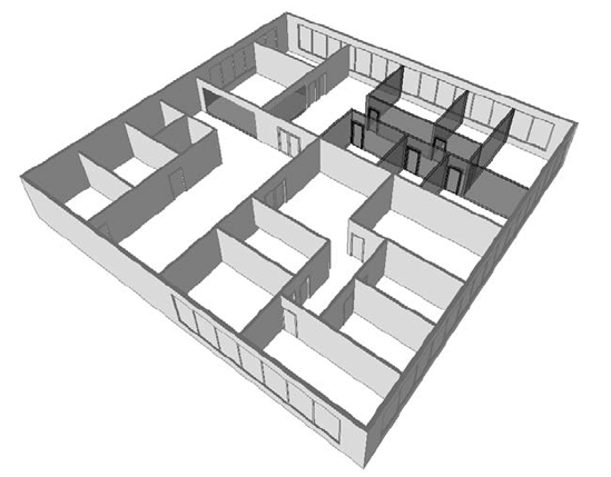
Here's the existing condition of the space from the previous exercise. If you haven't created the file to this point, go ahead and download that file to get started. Before you create your facsimile, remember that this will be the existing condition. So rather than create the existing walls and then change their phase, let's start by duplicating a view and changing the view of that phase so that the walls and other content are already on the existing phase.
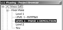
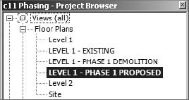
Duplicate Level 1 and rename it to LEVEL 1, EXISTING, as shown here.
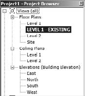
Then click inside the view to activate the view's properties; make sure that the phase is set to Existing.
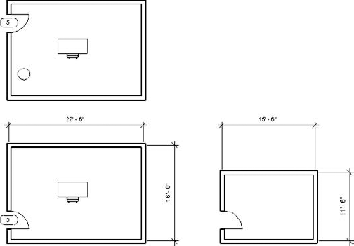
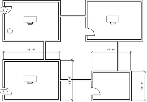
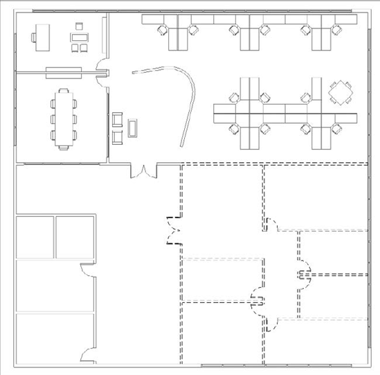
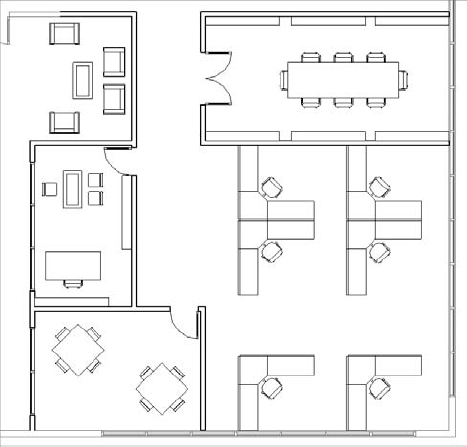
Leave the phase filter to Show All for now. Don't be concerned that the elevation tags have disappeared in the view. View tags are also phase aware, and they're in the New Construction phase. The overall space is 80' x 80'. We've also added some exterior dimensions as a reference. The finished exterior plan is shown here:
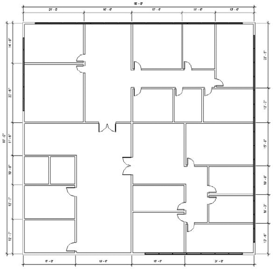
As you can see, the finished existing space is really two areas. In this scenario, the tenant in the lower-left space is expanding and will be taking over the upper space.
The idea is that we're going to demolish the space in stages. We don't want to upset the existing tenants to complete the phased work.
Some of the existing walls will remain. But you don't want to demolish them in this view. That's because the demolition should take place at the start of New Construction. But there's going to be two construction phases (so there will also be two demolition phases). If you haven't created those two phases, do so now, as shown here.

Now let's duplicate Level 1 again and rename as shown here. This will be the view that contains the demolition.
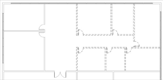
Now go to that view and be sure to change the phase and phase filter, as shown here.

Now demolish the walls as shown here. As a shortcut, you don't have to demolish the doors if you demolish the walls that host them.
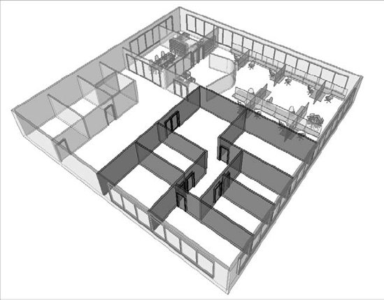
Now let's add the new elements. First, we'll replace a portion of the walls around the upper-left spaces with storefront. Since this is proposed, and the walls exist, it will automatically demolish the openings. The graphic shown here is a perspective of the work thus far. Recall that we've shaded the existing walls so that they'll stand out more from the proposed walls and the demolished walls are in shown in red.
Phase 1: Proposed
First, let's duplicate Level 1 and rename as shown here:
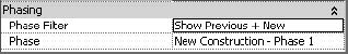
Make sure that the phase and phase filter are set as shown here. This view will only show the existing elements that remain after demolition and the proposed content.
Now we'll start adding furniture to the space. We'll add a reception area and other office furniture. Add desks, tables, shelving, and chairs, as shown here:

Now let's start adding open office furniture. But let's group the assembly before we start copying through the office space.

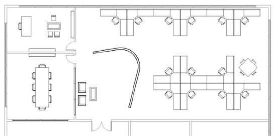
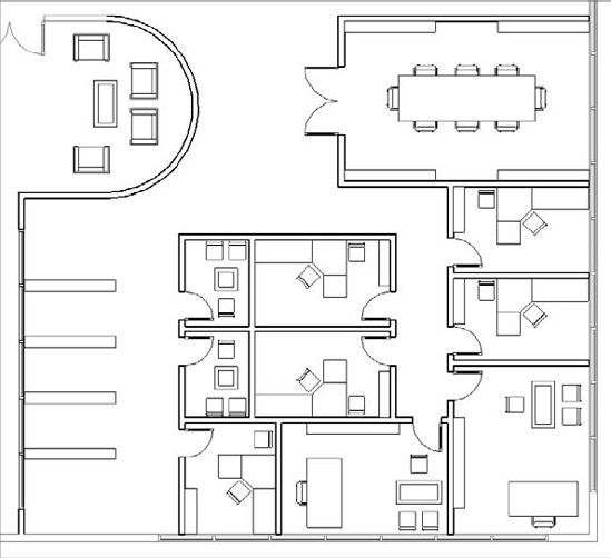
The graphic shown here is the completed space in a plan view:
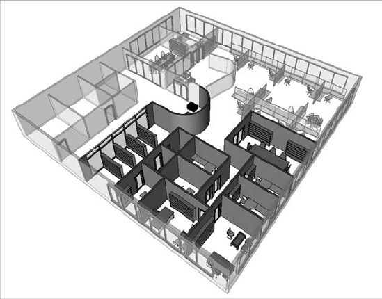
The graphic shown here is the space in a perspective view. Note that the demolished walls are not being shown. To give some graphic clarity and allow you to see through the context of the existing walls, we've temporarily set the transparency value of the existing material (in the phase properties) to 50%.

Let's start by duplicating Level 1. Then rename the view to LEVEL 1, PHASE 2 DEMOLITION and set the phase and phase filters as shown here:
Now demolish the existing walls as shown here. Note that you'll have to split the long wall between Phase 1 Proposed and Phase 2 Proposed in order to allow only a portion of the wall to be demolished.
The graphic shown here is a perspective view showing the proposed demolition for the second phase. Don't be confused by the proposed content from the previous phase showing as existing. This is correct, since that content is now considered existing when seen through the lens of the second phase.
Phase 2: Proposed
Now let's duplicate the view again for the start of proposed work. Duplicate Level 1 and rename it to LEVEL 1, PHASE 2 PROPOSED. Set the phase and phase filter as shown here:

Start working in your new plan view, adding proposed elements as shown. Don't worry about getting the design right—just get the idea right. Here's the plan view:
Just remember, adding elements in the view with the appropriate phase and phase filter settings is the easiest way to avoid confusion. Here's a perspective of the same view:
Now that you're finished with the demolition and proposed work in both phases, take a moment to set up a perspective and then duplicate it three more times. Each of the views will show each phase sequence. Your Project Browser should look similar to this:

Except for the existing perspective, here are all of the tiled views thus far:

Now let's create a schedule for walls that will quantify demolition for each phase. As a side note, we believe it would be helpful to be able to create Multi-Category schedules that would allow both host and component categories to be scheduled at the same time—for example, being able to schedule demolition for both walls and doors in the same demolition schedule. But this is not presently possible. So we'll create the schedules individually.
First, there's no phase filter to show only demolished elements. We'll need to create this filter, as shown here:

You can visually confirm what it will show by applying it to a working view:
Now let's start by creating a schedule for walls that are being demolished by volume. We also need to estimate the cost of disposal for each phase. Create the schedule as shown here:
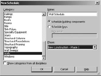
The following graphic shows the schedule fields that you'll need to create. You'll only be able to select the Type and Volume fields from the Available Fields selection.
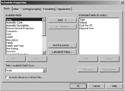
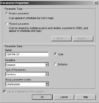
We'll also need to create a project parameter for the cost per unit volume (CF) per wall type. Click Add Parameter and fill out the resulting dialog box as shown here. Choose Type Parameter because we want to be able to add one value per wall type, not per each instance.
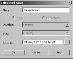
You'll need to add a Calculated Value in order to multiply the demolished units' volume by the cost per units and get the total. We've divided the Volume value by 1 in order to keep the units consistent, as shown here:
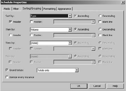
The Sorting/Grouping settings are shown here:
The Formatting settings are shown here:
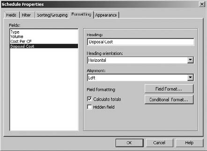
Here's the Formatting for the Disposal Cost Calculated value:

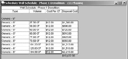
When you're finished, the schedule will appear showing with the following values. Your schedule will not be exactly the same because the amount of demolition will vary between this example project and your project.
For the Phase 2 demolition schedule, don't start over. Duplicate the previously created schedule and just change the phase, as shown here:
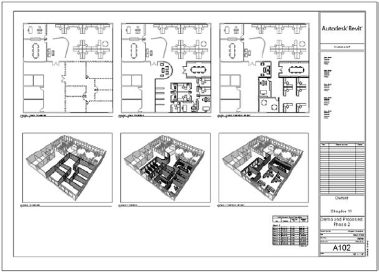
All that's left is to assemble the views on sheets. We'll only need to use two sheets. Each sheet will show a combined Phase 1 Demolition and Proposed views (plans, perspective, and schedules):

Everything looks great, but as to be expected, you need to show another option for Phase 2. This is really easily done!
First, create a new design option set and two options, as shown here. Notice that we've renamed the set for clarity.

Here's a great tip. To isolate what you need to assign to Option 1, set the phase filter to Show New elements. This will turn off any existing conditions from the previous phase.

Now select everything in the view, return to the Manage tab, and click Add To Set. Deselect Option 2, as shown here, and click OK. This will add everything to the Option 1 (primary) design option. Then set the phase filter back to Show Previous + New.

Now duplicate LEVEL 1 - PHASE 2 PROPOSED, and rename it to LEVEL 1 - PHASE 2 PROPOSED - OPTION 2. This will be your working view for the second design option.
Next, set the View Properties to show the second option:

Now make Option 2 active and create another design iteration, as shown here:
Now place this design option on the sheet next to the Phase 2 demolition and first option. You can also duplicate the perspective view of the first option; remember to change its Visibility Graphics to show Option 2, as shown here:
If you'd like to download the file used in this example, you can find it in the Chapter 11 folder; it's called c11_Exercise.rvt.
- Use phasing.
Time is such an important element to the design process and nearly impossible to capture with traditional CAD tools. Don't use phasing for construction sequencing (there's a better way). Embrace phasing for communication, not just illustration.
- Master It
How can you use phasing to communicate your design across a series of key stages? What kind of project is best suited to phasing?
- Know why you shouldn't mirror groups.
Groups are great for creating collections of both host and family component geometry. Just remember to use best practices and you'll avoid a lot of common roadblocks. Everything still schedules, as you'd expect. And creating exceptions in groups allows you to make subtle changes without creating a new group.
- Master It
Why shouldn't you mirror groups?
- Make design options for design iteration.
Like groups, design options work great when you work within the rules. Design options are intended for design iteration that is bounded and well defined—not for putting multiple buildings in one project file. Remember that links, groups, and phasing can exist within design options. Always keep hosted elements with their host when using design options.
- Master It
Suppose you have a multistory tower. How could you show repetitive curtain wall options?