
If you're not designing or documenting a building, you're probably designing or placing the stuff that goes inside it: structural members, doors, furniture, lighting, equipment, and more. And if you think about it, this effort is a significant part of the design process. If the surrounding walls, floor, and roof or ceiling contain the space, it might be said that the content describes the function and utility of a space. In other words, content provides context. In many respects, it gives the space meaning. The rhythm of placement, orientation, and elevation of content can turn a mundane space into an elegant and memorable one.
In Revit, the Family Editor is where you'll model all the content that isn't built as part of the project. And if you're familiar with other 3D modeling applications, the good news is that it will be easy to get started. But the really great news is that if you've never modeled in 3D, you have nothing to lose.
The key isn't just being able to model; you can model in 3D in lots of applications. The Family Editor offers the ability to make content that will flex appropriately as your design changes; you can iterate your design without starting over. Sometimes you'll need to change the height, width, or length. Other times you'll need to modify the material. And in some cases you'll nest geometry into another family in order to create assembled options on the fly.
Creating content in Revit often involves assigning parameters. At first, parameters might seem new and scary. But parameters are just values that you assign to what you're making so that you can quickly and easily change it, and there's no programming involved. This is so much superior to how you're probably used to modeling in 3D in other applications, where changing a model often means storing and then manually recalling endless earlier versions.
So relax, and prepare yourself for getting excited about design. Once you get your mind around creating parametric content in the Family Editor, you'll probably realize you can do anything in Revit.
In this chapter, you'll learn to:
Understand the Family Editor
Choose the right family template
Create and test parameters
Know why formulas are important
Plenty of generic 3D modeling applications allow you to create content that will be used in designing your buildings, and modeling in 3D is certainly a big part of the Family Editor. But the key to the Family Editor isn't that you're modeling "anything" but that you're modeling "something." Something specific. The thing that you're trying to design is meant to be a particular thing and behave in a particular way.
So when you're modeling in the Family Editor, you're not just trying to model how and what something is, you're also trying to predict how it might change. Anticipating change is key to creating great, flexible content that is able to quickly and easily change as your design changes.
For example, take a simple table. If you were to model this in something like SketchUp, what you'd have when you're done is exactly what you've modeled. But think about the design process and how something might need to change: height, length, width, and material. In the real world, each of these parameters is really important. Say, if you have only three options for each of these values, this results in 81 (34) permutations! Who has time to manually create each of these options? But this is what you'd have to do if you were using a generic modeler rather than something like Revit, where these options are simply driven by rules. And just imagine what would happen if you needed to create another set of options! In Revit, creating another option can be done on the fly.
As you probably know, your design is going to change. Being able to anticipate change will help you not only understand how best to approach Revit but also how to keep from becoming a frustrated designer, faced with what seems to be unpredictable whims and demands of your clients, consultants, and contractors.
We'll start by putting the Family Editor in context. Without oversimplifying or complicating matters, think about how you'd organize a design problem: constraints, building, content, documentation, and workflow. Interestingly enough, this parallels how Revit also views the design process: data, host families, component families, views, and worksharing.
- Data
Before you start designing in 3D, you're going to need some context! What are the likely levels in elevation or key structural locations in the plan? Data helps give context to almost all the building and project components. And without data (at least levels), it's impracticable to start designing your project. Fortunately, the default Revit template has two levels, and the default view is level 1.
Keep in mind that everything you create in the Family Editor needs to understand its relationship in the project. And even if it's not relating to geometry, it's relating to the data in the project: a grid or level. Knowing how your family component will respond to data in the project environment is critical.
- Host Families
In Revit, the main building elements are called host or system families. Host and system families are all geometry, but it's geometry that's built within the project environment, not in the Family Editor (although some host families may contain component families). Walls, Floors, Roofs, and Ceilings are the most common host families.
After data, families often need to be hosted by system families (or at least need to maintain a particular relationship). You need to know whether your family will have to maintain some relationship to system families in your project.
- Component Families
Component families are created outside the project environment. They're loaded into the project and then distributed as needed. When you change the Type Properties of a component family, you're changing the properties of all components of the same type. But when you change the Instance Properties of a family component, you're changing only the instances that you've selected.
- Views
The views of your model include schedules, 2D views (plans, elevations, and sections), 3D views (orthographic and perspective), or even drafting views for drawing whatever you like and then associating it with the model.
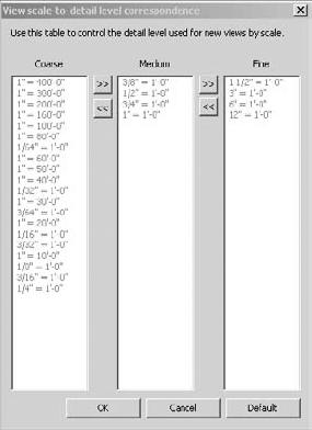
Many views have scale- and detail-level properties. The detail level is particularly important to consider when creating a family component, because you often don't need to show every facet and detail in every view and scale. Fortunately, this view scale-to-detail level relationship is automatically defined in Revit. So, once you place your family component in Revit, it will automatically hide or reveal detail based on the scale of a view in your project (Figure 15.1).
- Worksharing
Finally, worksharing allows all your team members to access the Revit project at the same time in a flexible, nonlinear manner. One moment you're moving a wall, the next moment you're adding a door, and the next you're adding a tag or changing the look of the schedule. Revit is able to handle this kind of nonlinear and unpredictable change quickly and easily.
Note
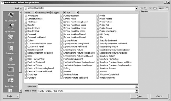
Now that you have a better understanding of where your component families sit in relation to your overall project, we'll discuss some specifics. If you attempt to create a new family (Revit
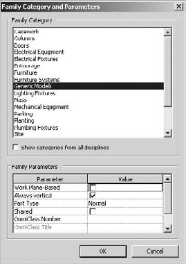
Selecting the right template determines a lot of behavior about the family. In some cases, you can change the category of the template that you've selected from one to another. For example, in Figure 15.3, a Generic Models family template is capable of being turned into another template. This is helpful if you need a family to schedule in a different category than one you might have initially selected. But in many cases, categories cannot be switched, and nonhosted or non-face-based components cannot be changed to hosted or face-based (and vice versa). That's why you need to choose the category carefully.
Some categories are hardwired for specific behavior, and if you change from that category to another, you can't go back. For example, if you start a family in one of the baluster templates, you can switch to another template. But after having done so, you cannot switch back to a baluster family.
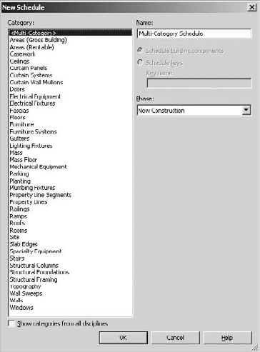
In addition, keep in mind as you start a new component that the category you select ultimately controls how the family component will schedule. So, if you're trying to determine which template to select, it will be helpful to ask yourself or your team members how the family should schedule. Figure 15.4 illustrates all the schedule categories that are available in Revit.
Another important characteristic of the family category is that it will control whether a family will "cut" when intersecting a view plane (plan, section, elevation, and so on). For example, convention dictates that when furniture encounters a cut plane, you should show a projected view.
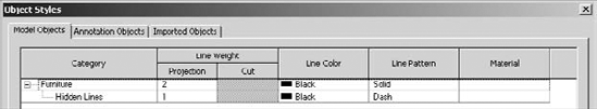
Revit respects this convention by cutting some categories while not cutting others. You can figure out which categories cut or don't cut by going to the Manage tab and clicking Object Styles (Figure 15.5).
As you can see in Figure 15.5, categories such as Casework, Ceilings, and Columns cut, while categories such as Electrical Equipment, Electrical Fixtures, and Furniture do not.
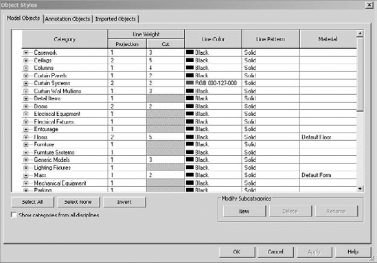
Another important characteristic of the object properties is the default line weights given to objects when they're placed in a project. These line weights effect both projection and cut values. Just remember that it's probably best not to manipulate the Line Weights dialog box (Figure 15.6) unless you know what you're doing. If you intend to increase or decrease the line weight of a category of objects, use the object properties rather than the Line Weights dialog box.

As you start to get into the parameter that can control a family's geometry, material, or other value, keep in mind that it's not always necessary to create components as fully parametric. This is especially true of the first pass. The location and spacing of content is often more important than whether the family can flex geometrically.
Nonparametric families often occur when the component being modeled is specific and highly unique. It may have parameters that control materials or a few other values, but not much more. At this point, little more than selecting the right category and insertion point is necessary. It's often far more efficient to maintain design relationships by modifying the component in the Family Editor and then reloading it into the project'at least until more is known about the design. When more is known, you can open the family and embed more parameters.
Now that we've discussed some of the basic definitions and rules of the Family Editor, we'll talk about the hierarchy of creating a family component. As previously discussed, not all families are created in the Family Editor. Host families, for example, such as walls, floors, and ceilings, are created directly in the project environment. It's possible to create component families in the project environment, but it's important, in most cases, that you not do this.
Creating "in-place" families is often a dead-end process that will rob you of hours of otherwise productive time for a number of reasons. First, an in-place family should be used only in cases where the object that you're making is not likely to be moved, rotated, or copied. Any attempt to move, rotate, or copy an in-place family can often have unintended consequences that are difficult to pinpoint. For example, if you model an in-place family and then create copies in your project, they may all initially look the same, but in fact you're copying new instances. So, modifying one of the instances is going to leave the others untouched, which can be frustrating if you've copied the instances thinking that later changes would ripple through the project.
Second, each copied instance will schedule independently from the other instances as separate line items. This is often not desirable, as you may want to group like elements together in a schedule.
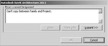
Finally, there's no way to convert an in-place family into a component family. In some cases, you can copy and paste sketch lines or other 2D elements between the project and family environments. But if you try to copy and paste geometry from the project environment to the Family Editor, you'll get the warning shown in Figure 15.7. The only way to proceed is to start again in the Family Editor.
The bottom line is that if you're going to use more than a single, highly unique instance in a project or across projects, it's probably best to create the component in the Family Editor, not as an in-place family.
So, you need to consider the following criteria before you create a family component, particularly since some of the criteria can't easily be changed (if at all). You'll probably have to start over if you choose poorly. We've also tried to order the criteria for creating a family component from most to least restrictive. Most restrictive means you may have to start over. Least restrictive means you may get away with changing a parameter or value after you've already started the family.
Note
The first and most important question you need to ask yourself as you select your template is whether the family is meant to be hosted or nonhosted. If you choose poorly here, you'll likely have to start over. For example, if you start a window as a nonhosted element and then want to make it hosted later, you'll probably be better off starting over.
First, keep in mind that hosted objects are meant to cut their host or create an opening or depression. Obviously a window (with few exceptions) needs to cut the wall that it will go into. Or a fire extinguisher case will often need to create a recess in the wall in which it will be placed. Second, if the component is to be hosted and you're certain that it needs to create an opening in its host, it can only cut one host. For example, a window that is wall hosted may not be hosted by a roof or ceiling.
Want to see a bad example of this? Open the Tub-Rectangular-3D family component in the Family Editor that comes with Revit (Figure 15.8).
What's wrong with this picture? Well, first, not all tubs need walls, so you'll have to make another family that has no host in order to place the tub where there is no wall. This seems a bit redundant, because one tub will do.
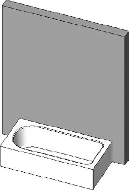
Second, if you delete a host, all the nested elements are deleted as well. This makes some sense when you delete a wall that contains a window. But it will certainly lead to a lot of frustration if you delete a wall that contains bathroom fixtures!
But what if you want the tub to move with the wall? There's a better way. Simply place the element and select the Moves With Nearby Elements option (Figure 15.9). When the host moves, the component will move as well.
We can't stress enough: stay away from creating hosted relationships between objects that do not require hosting (that do not cut or otherwise modify the host). This brings up an interesting point of debate, though. Rather than use hosted elements, why not make elements face-based? There are some interesting advantages:
You don't have to decide on a particular host. Any surface will do: Wall, Ceiling, Top Of Casework, anything that has a face. This is great if the lighting component you're creating needs to cut into a wall, floor, and ceiling!
A face-based element can cut the face of geometry in both the project and family editing environment. So the light fixture that cuts a wall in a project can cut the face of a piece of casework in the Family Editor.
Deleting the host will not delete the component. Is this always desirable? Well, maybe yes and maybe no. But what's important is that you have the option if the component is face-based. You won't have the option if the component is hosted.
This brings up one last point with regard to hosting and face-based elements. Why not simply model the elements, share the parameters, and then nest? This often gives the most flexibility.
Note
After you've chosen whether you're going hosted or nonhosted, you need to choose the correct family category. As mentioned earlier in the chapter, this is also critical. The reason you need to select the category carefully is because some categories can be switched after the fact, but this is not always the case. This is particularly true when the component has behavior that is specific or unique.
For example, lighting fixtures contain elements that allow the light to render once placed in the project environment. Balusters are another example of elements that have specific behaviors built in. If you don't select the appropriate category, you may find yourself starting over.
Note
Now that you've defined the hosting and family category, the rest is pretty flexible. If you choose poorly, you'll probably be able to recover most if not all of your work if something needs to change. But some considerations should come before others, which is why we believe that the insertion point is the next most critical criterion on your list of family creation.
The insertion point determines the location about which the family will geometrically flex'not just in plan view but also in elevation. The reference level in the Family Editor directly corresponds to the datum level in your project. Keep in mind that not only does this relate to the visibility of your component in a view, but it also relates to how the component will schedule. This is important for a couple of reasons. First, when the family expands or contracts geometrically, the insertion point will remain relatively fixed.
But second (and often more importantly), the insertion point is the point of reference when two family components are exchanged. This is critical if the "design" family that you've used as a placeholder is being swapped out for something more specific at a later date. If the insertion points are not concurrent, the location of the new family will not agree with the location of the old one.
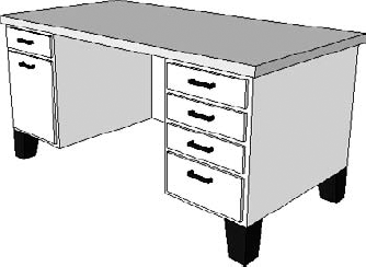
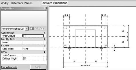
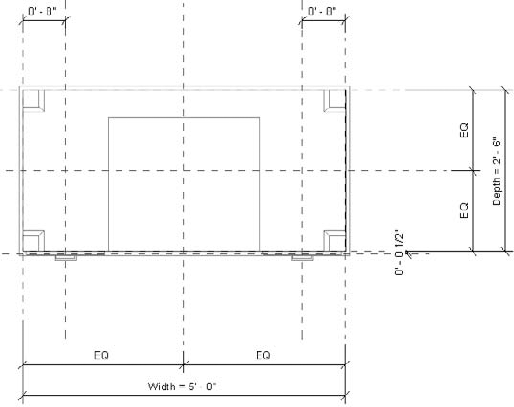
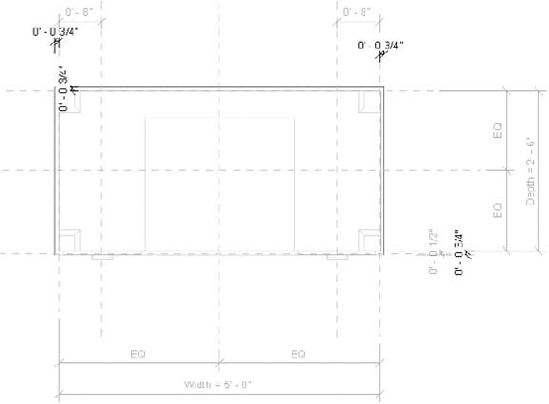
For example, the default Desk.rfa file in the following example has the insertion point located at the center of the object (Figure 15.10). This means the desk will flex about this point. But this is not desirable if the desk, table, or furniture object has a different insertion point that you are about to swap out for this example or if the family needs to flex from a different location.
Keep in mind that changing the insertion point is easy. As you would expect, you don't move the geometry to the insertion point. Rather, you simply select two reference planes and then make sure the Defines Origin option is selected. Based on our experience, we recommend that the insertion point for this particular family would best be located at the face of the desk, as shown in Figure 15.11. This would allow the desk to flex with respect to the seating, so that if the desk is larger or smaller you won't have to spend time relocating all the chairs.
If you're confident that what you're about to model in the Family Editor will need to flex (length, angle, location, and so on) from within the rules of the family (not just within the project), then it's important that you start modeling the geometry by first creating the rules that will allow the geometry to flex.
With little exception, you don't want to give parameters to the geometry itself. You'll want to create the necessary reference planes, lines, and points first. Then associate the parameters to these references and whenever possible test the parameters to make sure the references are flexing properly. Once you're confident the references are flexing, you can build the geometry in context to the references, again testing to make certain that when the references flex, the geometry is flexing as well.
Which reference you use is based on how you want the geometry to flex:
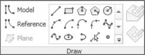
- Reference Points
These have three planes that can be set to host sketch lines or geometry. You can also use a series of points to control a line or even a spline. Other objects such as reference lines or other geometric surfaces can also host reference points. You can select reference points from the dialog box shown in Figure 15.12.
However, reference points are available only in the categories of certain families: Mass, Adaptive Mass, and Curtain Panel Pattern Based.
- Reference Planes
These define a single plane that can be set to host sketch lines or geometry. They're best for controlling linear geometric relationships. Reference planes don't have endpoints. This is important because you don't want to use reference planes for controlling angular or directional relationships.
The linear relationships of length, width, and height are perfectly well suited for controlling the geometric parameters of the desk default
Desk.rfafamily component. All of the geometric options are parallel to one another (Figure 15.13).- Reference Lines
These by definition have endpoints and are great for controlling angular and directional relationships. They can have four points of reference, two along the length of the line (which are perpendicular to each other) and one at each end that is perpendicular to the line.
You can also create curved reference lines, but they only have planes that may be used for hosting at each end. There are no references along the curved line (Figure 15.14).
The great thing about reference lines is that because they contain endpoints, they're able to manage angular relationships.

Here's a simple tutorial for parameterizing reference lines. Don't even try this with reference planes. It would break'because by definition, "planes" don't have endpoints. So when you try to parameterize an angular value between two reference planes, they tend to lose their angular origin. Fortunately, lines have endpoints, so controlling them from an endpoint is far more predictable.
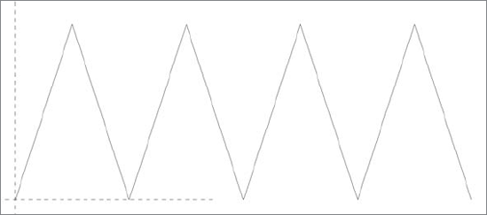
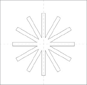
First, open a Generic Model template and draw a series of connected reference lines. If you are deliberate and make them all the same length and angle, it'll save some time. Here's what you should have when you're finished:
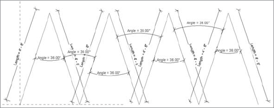
Now take a moment and add length and angle dimensions to each of the lines. Then parameterize all the length parameters together, and then do the same things for the angles. If you've drawn your reference lines carefully (all the same length and angle), you'll be able to parameterize them by selecting the dimensions all at once. If they're different, you'll need to select each length (and each angle) one at a time and associate with the appropriate parameter. When you're finished, it should look like this:
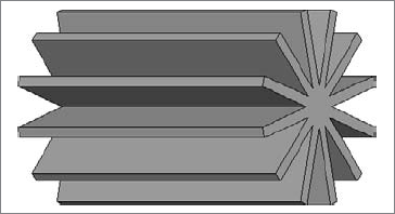
Now comes the interesting part: create a single swept form by picking each of the reference lines together. After you've finished your sweep, you'll realize that when you flex the angular and length parameters, the sweep will remain associated with the reference lines.
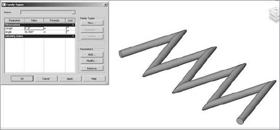
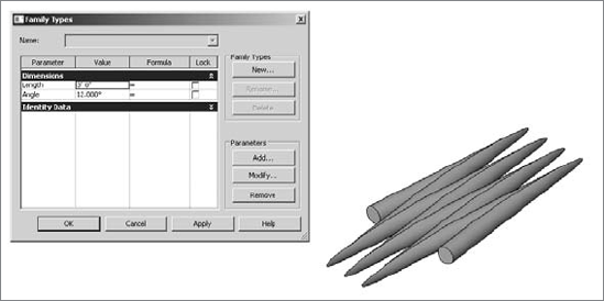

With this technique, you can imagine that modeling accordion panels shouldn't be a problem. You can show the panels as open or closed, driving the individual segment lengths from an "overall" length that is divided among the individual segments.
The time it takes for Revit to generate or regenerate a view depends on how much stuff in the view needs to be displayed. One of the great things about Revit is that it automatically assigns the level of detail based on the scale of the view (Figure 15.15).

When you're building smaller parts of a larger component (or if the elements are not visible in certain orientations), you should assign those elements to only reveal themselves at a certain level of detail (or only certain orientations). This will keep Revit from having to manage more information than necessary. Here's a rule of thumb: once the separate lines that represent something print as a single, merged line, there's little point in having that element display in that view or at that scale. Although this was an entirely intuitive realization when drawing with a pencil (don't draw over the same line twice), unfortunately computers have allowed us to draw beyond a point of diminishing returns.
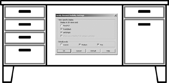
To see how to fix it, open the default Desk.rfa family, which is fairly well built. But if you look closely, you'll notice that orientation and detail level are not being fully specified. All of the drawer faces and hardware are showing up at every view in every section or elevation.
In this Desk.rfa family, everything is showing up in every level of detail. This isn't necessarily a big deal with just a few objects. But multiply this by all the other elements that will make up your plans, reflected ceiling plans, elevations, and sections, and you'll notice that your views don't refresh, rotate, print, and export as fast as you'd expect. When this happens, one of the first things we look for is an object in a view that is being shown at a level of detail that is far too high. In some cases the object only prints as a small, black dot. But when you zoom in you'll notice that it's full of detail.
Controlling the detail parametrically is done through the Family Elements Visibility Settings dialog box (Figure 15.16).
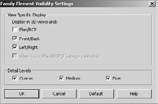
Notice that the box for the Plan/RCP option is unchecked? This is appropriate for the desk, because little more than the surface of the top of the desk needs to show up in plan. The legs, the hardware, and even the faces of the drawers don't need to show up in plan.
But what about the elevations? By turning off the Thin Lines option, you can see that all the geometry is showing up at every level of detail in a view that's set for 1/8' = 1'-0" (Figure 15.17).

In these cases, Zoom To Sheet Size is your friend. Figure 15.18 shows the same desk in elevation when that option is active. It's obvious that we'd never need that level of detail at that scale.
It's pretty obvious that there's far more detail than necessary for this view and the solution is simple. Set the drawer faces to show up at a Medium detail level or finer, and set the hardware to only show up at a Fine detail level. Do this to all your content and performance should noticeably increase (Figure 15.19).
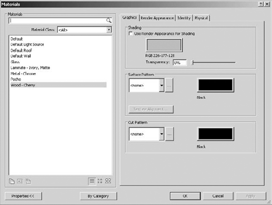
Materials are crucial to a family. But keep this in balance'don't obsess about the material that will display when a family is being rendered. What's more important is the Shading setting and the Transparency value of the material because they communicate much about the intent of your design in the early stages (Figure 15.20).
In addition, material options are often not easily created in Revit. Yes, a family can have a material parameter. But expressing many different parameters for visualization purposes is probably left to the visualization specialist who understands the subtleties of creating an emotive image, not just a "rendering"—and it's unlikely they'll be using Revit to iterate or emotively visualize your design.
As mentioned earlier, dimensions are useful for controlling the geometry parameters of your families. But it's best to keep the dimensions outside of Sketch mode. Let's use the desk as an example. In plan view, you can see all the reference planes and dimensions (Figure 15.21).

Now select the top of the desk and select the Edit Extrusion option. What you'll find are dimensions to the edge of the desktop (Figure 15.22).
These dimensions are "inside" the Sketch mode of the desktop. This is fine in the sense that they'll work. But as a best practice, don't put parameterized dimensions inside Sketch mode. The reason is that when you complete the sketch, the dimensions will be hidden. Then when you're trying to troubleshoot or modify parameters, you won't be able to easily find the values that correspond to in the model view.
So whenever possible, keep all dimensions outside of Sketch mode.
Revit has predefined a number of hardwired family categories. These categories can't be modified or added. As mentioned earlier, they define how elements display, schedule, export, and so on. But within the default object categories, you can create subcategories for model, annotation, and imported objects (Figure 15.23).
Although you can use subcategories to control the visibility of some part of the whole component, keep in mind that the detail level and visibility settings already manage visibility. The subcategories are most important when you're exporting your project, because each category and subcategory is permitted its own CAD layer (Figure 15.24).

So if your project is being exported to CAD in such a way that you'll need to associate objects with granular layer settings, creating and assigning subcategories to elements is necessary. But don't rely on subcategories to manage visibility.
Note
A lot of users new to Revit start to panic when they have to select between a type and an instance parameter. Just keep in mind that you can change these two items after you set them initially. When you reload the family into the project environment, the previous settings will be overwritten.
The key difference is that modifying a type parameter will always modify all the other components of the same time. On the other hand, an instance parameter will only modify the components that you have selected. Figure 15.25 shows the parameters of the default Desk.rfa family.
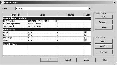
You can tell all these parameters are type parameters because any time you have an instance parameter, the text "(default)" appears after the parameter value. In this case, it's likely important that the dimensions are type parameters. You don't want users to create random or arbitrary Depth, Height, and Width values.
On the other hand, each new option can create a lot of new types. By default, loading a family into your project will also load all the types. If you want to create the potential for many types but be selective about which types are loaded, you can use a type catalog to load only specific types.
Creating complex geometry isn't always as easy as opening the Family Editor and starting to model the shape that you think you're trying to create. Sometimes you need to model one form in order to create another form. And sometimes you need to model a complex, parameterized form in order to parameterize the actual shape that you're trying to create. So that you understand these advanced techniques, we'll first cover the available geometry types that can be created in Revit.
There are five discrete geometry types in the Family Editor: extrusions, blends, revolves, sweeps, and swept blends. Both solid and void forms can be modeled from these shapes (Figure 15.26).
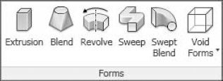
Which one you select is important, but our advice is to use the simplest form that will express what you're trying to model, keeping in mind how the geometry is likely to change.
In other words, an extrusion, blend, sweep, and swept blend can be used to create initially similar forms. It's impossible to tell them apart (Figure 15.27).
But once these forms change, you'll understand that they can iterate into very different shapes (Figure 15.28).
One of the great things in Revit is that the relationship between solid geometry and cutting void is nonlinear. Solids that are joined together may still maintain independent relationships. They're not locked together after they're joined.
Additionally, not all voids must cut all solids. The void may selectively cut one solid but not another solid, even though the two solids are joined together. For example, in Figure 15.29 we've joined the solids from the previous image and overlapped them with a single void. Notice how the void is cutting all of the joined solids.
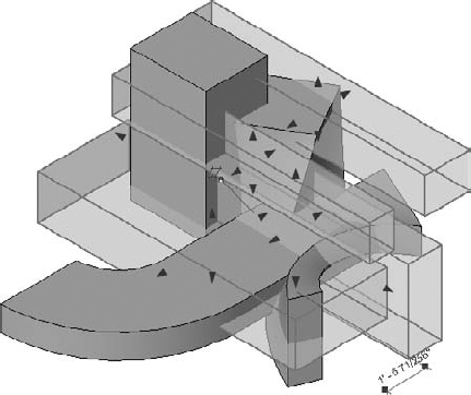
Figure 15.30 shows the results of finishing the sketch.
This is often not desirable because now you'll have to go back and "uncut" three of the four joined solids. So in many cases you'd rather model a void that only selectively cuts. The trick here is not to model the void as a void. If you do, then by default it will cut all the solids that came before it. Rather, model the geometry as a solid (Figure 15.31).
Now you can convert the solid to a void from the Properties dialog box, as shown in Figure 15.32.
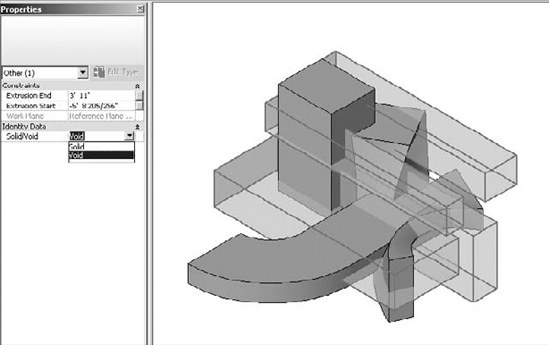
Figure 15.33 shows the results. The void doesn't cut any of the solids. This is desirable when you want to complete the void and still see it, because by default, once a void cuts a solid it becomes invisible, which makes it rather hard to find. This technique still shows the void for editing (Figure 15.33).
Now you can selectively cut only what you want to cut (Figure 15.34).
To review this file, you can download it from the Chapter 15 folder at the book's web page (www.sybex.com/go/masteringrevit2011); it's called Solid Void.rfa.
If you're really 3D savvy, creating complex geometry often involves creating what you need with complex modeling tools in order to reach some final result. The process in Revit is often different and has some wonderful benefits as well.
Think of a sculptural process as being additive or subtractive. Creating sculpture as an additive process means that you're casting the desired shape. Creating sculpture as a subtractive process means starting with more stuff than you need and then carving away until you have the final result.
Many complex geometry applications create complex forms as an additive process. In other words, you create a form and then manipulate that result with other tools; pushing, pulling, and twisting until you've morphed the final shape.
Think of Revit as more of a hybrid process that relies heavily on a subtractive approach that carves away what you don't need. Although this may seem a bit counterintuitive at first (because in many 3D modeling tools, cutting geometry is a linear process that doesn't lend itself well to parametric editing), in Revit the void is a live thing that can be quickly and easily modified.
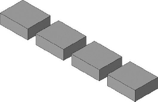
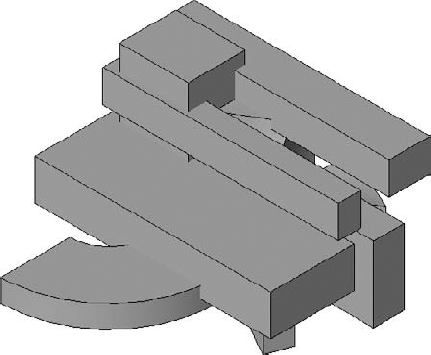
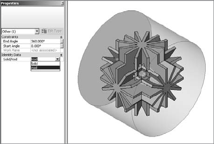
For example, you may not believe that the form shown in Figure 15.35 has been created in Revit. If you're trying to create this form using an additive process, it's quite complicated. But if you create it using a subtractive approach, then it's quite easy, and the results can be surprisingly elegant.
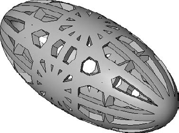
Furthermore, the form consists of only three (copied) extrusions and a single void. But it's easily done and with just a few steps.
Creating that sculptural form is not hard. Don't believe us? Follow these steps:
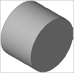
Create the extrusion sketch shown here in a Front/Back elevation. In this case, the overall height is 6'. The width is 0'-4".
When you finish the sketch, set the overall length to 9'-0". This is the resulting shape.
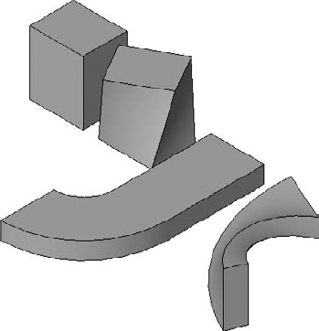
Go to your Left/Right elevation and use Copy/Rotate to move the form 90 degrees so that the copy is vertical. You'll also have to select the Disjoin option.
Go to the Top/Bottom view and use Copy/Rotate to move the original form 90 degrees to that the copy is facing left/right.
Use the Join Geometry tool and join all three forms together. When you're done, the form should look like this:

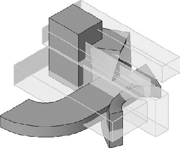
Now it gets really interesting! We'll show you how to cut multiple solids from a single void after you initially modeled the void as a solid. Here's the sketch of the solid revolve in the Front elevation:

When you finish the form, you want to make certain that none of the geometry from the star form is showing outside the revolve that you've created, as shown here:
Change the solid revolve into a void. The void won't cut! This is what you want: the ability to model solids and voids with the flexibility to cut the void when you're ready, not before.
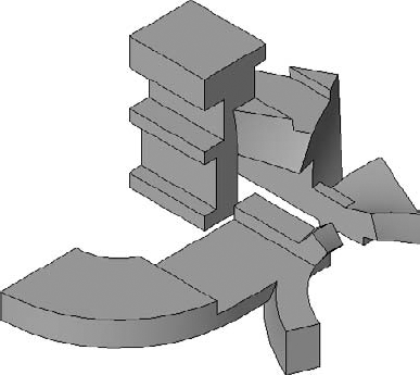
Here's a tip for cutting a lot of geometry with a void without having to select elements one by one. First, select the void and select Cut To Clipboard (or press Ctrl+X). This will remove the void! Don't worry.
Select Paste

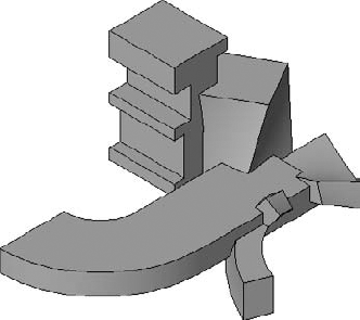
As a result, you should begin to understand that complex form making in Revit is quite often a subtractive process'you create more geometry than necessary and then use a void to carve away what you don't need.

There are some great examples of creating sculptural forms in Chapter 26. Carving geometry is a technique that set designer Bryan Sutton (profiled in that chapter) uses extensively. If you want to explore this file further, just look in the Chapter 15 folder on the book's web page for the file Egg Sculpture.rvt.
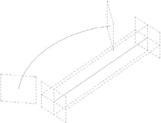
As discussed previously, reference planes, points, and lines are most often used to drive geometric form. If you've been using Revit for any length of time, you've been creating parametric content. But there will be some cases where these three options alone are just not enough. This is particularly difficult with linear or tubular forms, as shown in Figure 15.36.
To learn how to drive geometry with geometry, follow these steps:
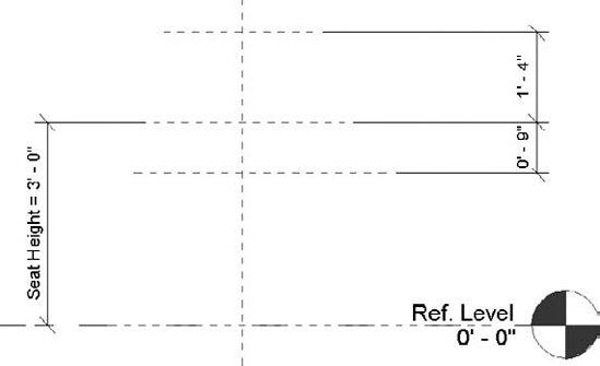
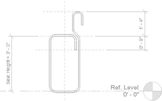
Open a Furniture template, and add reference planes to control the height of the seatback and the seat. Figure 15.37 shows the reference planes and other locked dimensions.
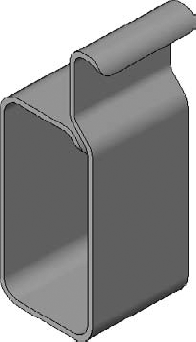
Now you'll model the "negative space" that would define the centerlines of the tubular structure with a solid extrusion. Make the overall form 20" wide. Once you finish the line of the inner sketch, simply offset about 1" or so (Figure 15.38).
Figure 15.39 shows the finished form. Now you have to start adding the voids that will shape the back of the seat and backrest.
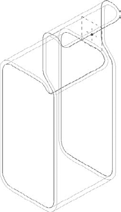
Create the two individual voids in the Front/Back elevation orientation (Figure 15.40).
When you're done, you've completed a path that represents the path of the structural tubing (Figure 15.41).
Select the Solid Sweep tool and pick the edges that make up the centerline of the structural tubing. Then sketch the profile that you want to follow along this path (Figure 15.42).
When you finish the path-based sweeps, you'll have the result shown in Figure 15.43.
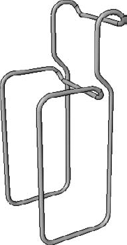
Figure 15.43. Edge-based sweeps with extrusion hidden
Model the extrusions for the leather seat and seat back. We've also added some additional reference lines to control the vertical location of the leather seat rest (Figure 15.44).
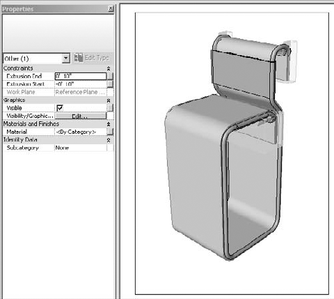
Now the tubular geometry is being controlled by the extrusion. But of course you don't want to see the extrusion in the project environment. This is easily fixed. Just select the extrusion, and in the Properties dialog box, deselect the Visible option under Graphics (Figure 15.45).
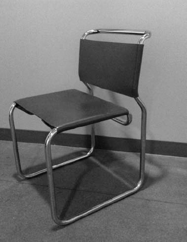


Once loaded into the project, the extrusion will be hidden, and because of the parameters that drive the extrusion, you can create new types (Figure 15.46).
If you want to explore this file further, just look in the Chapter 15 folder on the book's web page for the file Tube Chairs.rvt.
The real challenge in modeling in 3D is being able to predict and elegantly maintain change and iteration. Once you're able to do this, you really start to work effectively.
To get to this point, you need to understand nesting, family types, formulas, and type catalogs, and in the following sections, we'll walk you through an exercise that includes these techniques. Specifically, you'll build a simple shelf. A shelf is something we're all familiar with, and designing a shelf that elegantly changes with your design is a wonderful thing. Once you learn these techniques, you can apply them to many other concepts in Revit when you're creating elegant content.
The shelf family you will create in the following exercises will contain many brackets, so the brackets will be nested. Which bracket is used will depend on Family Type parameters. Then, the number of brackets will be controlled by formulas that add brackets as the shelf increases in length. Finally, you'll use type catalogs to select only the desired permutations.
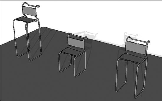
Figure 15.47 shows some possibilities for the final shelf.
You'll start by building one of the two brackets.
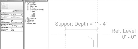
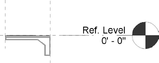
Open a Generic Model template. Starting in the Left Elevation view, create a reference plane to the left of the Center Front/Back reference plane to control the support depth.
Add a dimension from the Center Front/Back Reference plane (which is also the insertion point) to your new reference plane.
Parameterize the Length value as a Type Parameter, calling it Support Depth. When you're done, you should have what looks like Figure 15.48.
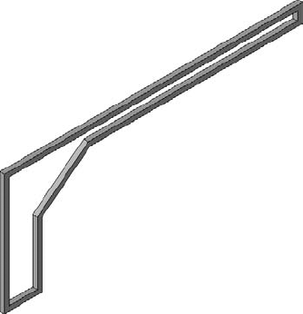
Sketch the extrusion shown in Figure 15.49. You won't need to lock any of the sketch lines. Their proximity to the reference planes will cause them to flex. We'll also change the overall thickness of the bracket to ¼", being careful to distribute half the bracket thickness to either side of the Center Left/Right reference plane.
Save the bracket as
Support 1.rfa. It should look like Figure 15.50.As a general principle, if you have to model an iteration that is similar to an existing example, don't start from scratch. Instead, open the existing example and modify it.
Click Save As, and call this new family
Support 2.rfa.Go back to the Left elevation and edit the previous extrusion. Offset the sketch lines ¼", as shown in Figure 15.51. Generally speaking, try offsetting sketch lines to create openings rather than adding voids. The results are flexible and faster to model.
When you finish the sketch, your new bracket should look like Figure 15.52. Now save the family, and you're ready to nest these two brackets in your shelf family.


To nest these two brackets in your shelf family, follow these steps:
Open a Furniture template (this is a shelf after all) and go ahead and nest both brackets into this template. Don't place them—just load them for later.
Close the bracket families, leaving only the Furniture family open. Finally, go ahead and save this new family, calling it
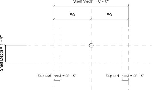
Parametric Shelf.rfa.Lets start in a plan view. As a rule, try to create all your reference planes and associated parameters in as few views as possible. This will save you time later.
Now create the additional reference planes, dimensions, and type parameters as shown. For reference, I've put a temporary circle at the default insertion point. Also note that when the shelf flexes, it will distribute evenly to either side of the Center Left/Right reference plane because of the EQ dimension below the Shelf Width length parameter (Figure 15.53).
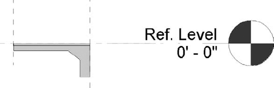
Now let's model the shelf geometry from this same view. Again, there's no need to lock any sketch lines to the reference planes. Also, note the Constraints in Figure 15.54. Extrusion Start is 0" and Extrusion End is negative ½". This means that the shelf is ½" thick. As a result, the top of the shelf will initially be aligned with the level it's placed on in the Revit project.
Return to your plan view and place the Support 1 bracket. Then go to the Right elevation and move the bracket into place, as shown in Figure 15.55, so that it's under the shelf. Just place one bracket. The rest will come later! Also, you don't need to apply Align/Lock to the bracket.
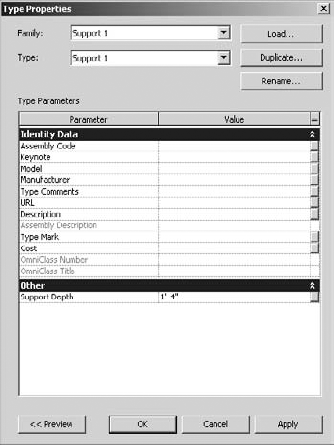
Now we'll associate the Bracket parameter with the parameter that controls the depth of the shelf. Select the bracket and then select Edit Type to bring up the dialog box shown in Figure 15.56. Note that the Support Depth value isn't associated with anything.
Click the square button to the far right of the Support Depth parameter. This will bring up another dialog box. Select the Shelf Depth parameter, as shown in Figure 15.57.

Now when the Shelf Depth length changes, the bracket will grow to match.

Now that you've nested the brackets and tested the parameters, you'll continue by adding Family Type parameters, which will allow you to select between the nested bracket families.
Note
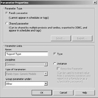
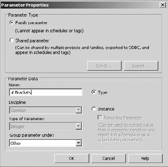
Select the bracket and look toward the top of the view. There's a value called Label. Pull down the menu and select Add Parameter, which will open the dialog box shown in Figure 15.58. In the Name field, enter Support Type.
Select between brackets in the Family Types dialog box. Set the Bracket Support value to Support 2. It's already associated because both brackets are of the same Generic Model category (Figure 15.59).
While you're in this view, select the Edit Type option, associating the Support Depth value of Support 2 with the Shelf Depth of this family (just like you did a moment ago for Support 1).
Now that you've associated Family Type parameters to the brackets, you'll continue by creating a parametric array in order to control the number of brackets on a case-by-case basis once the family is loaded into the project environment.
Return to the Front Elevation. Select the bracket, then select the Array command, and make an array with the following settings (Figure 15.60). Put the second bracket on the right side of the Center Left/Right reference plane.
Now you're going to parameterize the array. Select either of the brackets, and you'll notice they're now in groups. Now select the line that extends above the shelf and extends to either side of the groups. When you select this line, you'll be given an option to parameterize the grouped array (Figure 15.61).
Select Add Parameter, and complete the dialog box as shown in Figure 15.62. By default, the array has two brackets, which is fine for now. You'll parameterize this later.
Go back to the Front elevation and align/lock the brackets to the reference plane that is associated with the support inset. If you'll remember, we modeled the bracket on the Center Left/Right reference plane in its family. This reference plane is now a reference that you can use when the family is nested. As a result, you'll be able to use this reference when aligning and locking to the reference plane in the shelf project (Figure 15.63).


After you've aligned and locked both brackets, their locations should flex when you change the Shelf Width parameter. Go ahead and test this now. In fact, as a best practice, it's a good idea to test the parameters after every few steps.
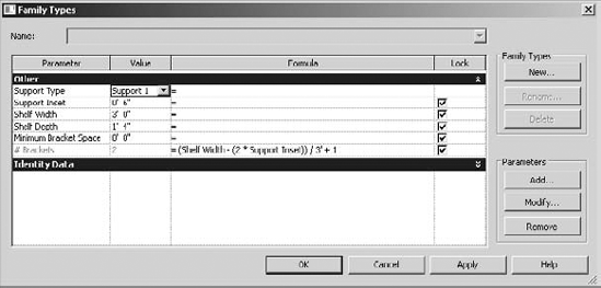
Now let's create a formula that adds brackets as the length of the shelf increases. We'll show how to do this simply at first, and then we'll add some complexity.
Open the Family Types dialog box. Rather than specify the number of brackets (# Brackets), add a formula to the right of this value under the Formula column:
(Shelf Width / 3') + 1
The reason that you add one to the end of the line is that if for some reason the width of the shelf is less than the specified width between brackets (3' in this example), then the number of brackets might result in one. But you're not permitted to have an array of less than two. A value of one would cause the formula to fail. And besides, a shelf with one bracket tends to be a bit unstable. And because we specified the first and last location of the array, this will guarantee a bracket at each end of the shelf.
Now that you've got down the basics, let's make the array more sophisticated.
Remove both the Support Inset values from the overall Shelf Width value:
(Shelf Width - (2 * Support Inset)) / 3' + 1
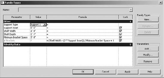
This is better. However, this formula also will lock the relative spacing between the brackets to 3'. If you want to keep the value flexible, you'll create a Length parameter that allows you to reiterate the bracket spacing.
Open the Family Types dialog box, and in the Parameters option select Add and then input the values shown in Figure 15.64.
Click OK, and close the dialog (Figure 15.65).
Reopen the Family Types dialog box, and use the parameter you've just created in place of the fixed 3" value. Give the Minimum Bracket Space parameter a value (or when you apply the formula it will not work). In this case, give it a value of 3'.
Substitute the text in the formula. Remember that spelling and case are important, so copy and paste will help (Figure 15.66).
Flex the family and experiment with different bracket spacing, shelf width, and support inset values.
Finally, it's not possible (or desirable) to set the actual or real bracket spacing. But it may be helpful to know this value as real-time feedback. So now you'll create the formula that will report this value.
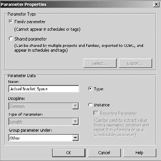
Open the Family Types dialog box, and click Add to create a new Length parameter, as shown in Figure 15.67.
Then add the following to the Actual Bracket Space formula field:
(Shelf Width - (2 * Support Inset)) / (# Brackets - 1)
This will report the real value of the bracket spacing, not just the minimum specified (Figure 15.68).


Now let's associate the material of the shelf with a parameter to control the material.
Note
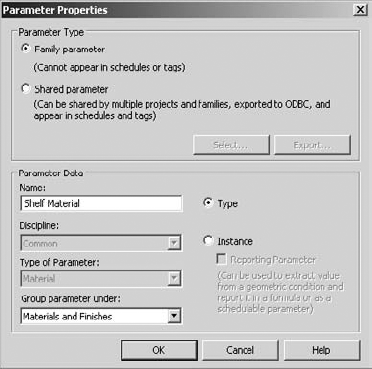
Select the shelf and then click the button to the right of the Material row (Figure 15.69).
Click the Add Parameter button in the Associate Family Parameter dialog box (Figure 15.70).
Add the Material parameter, as shown in Figure 15.71. In this case we've named the parameter "Shelf Material".


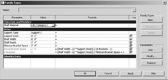
Now you can open the Family Types dialog box and see that the material of the shelf geometry has been parameterized to associate with a material (Figure 15.72). Once this family is loaded into the project environment, you can change the material of a shelf as a type. You'll also be able to specify the bracket, as well as the spacing of the bracket.
Now let's consider all the possible permutations of this shelf. Imagine the following:
How many Type permutations might exist?
Easy! 2 x 2 x 2 x 3 x 3 = 72 Types
That's a lot of types to build and load into a project, especially if you really only want to use just a few of the types in your project. You have a couple of options:
Some of the type parameters may work as instance parameters. That can reduce the number of types significantly. For example, if the material parameters became instance parameters, you could reduce the number of types by half. But still, that's far too many types.
You can create a type catalog. This lets you to store all the types in a text file that allows you to be selective about which iterations are loaded into the project. So instead of dozens and dozens of different types, you can just load the ones that you want. This will keep your file much lighter. Also, if you need to create additional types, it's a simple matter of adding the values to the type catalog.
Type catalogs can be intimidating at first because small errors will cause either the type catalog or the corresponding family to fail, so just go slow and test frequently. You don't want to test the catalog at the end of your process and be faced with untangling spaghetti.
We'll start simple. First, keep in mind that the type catalog needs to be in the same location as the family that it references, and it should have the same name. So in this case the family is called Parametric Shelf.rfa, so the type catalog will be called Parametric Shelf.txt. In addition, spelling counts, and parameter names are case sensitive as well, just like when you're working in the Family Editor.
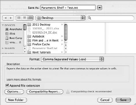
Parameter values can be expressed as length, area, volume, angle, force, linear force, and "other." For this example, we'll be using length (for lengths) and other (for Family Types). We'll use decimals when appropriate. While we could create this in Excel and export as a comma-delimited text file, we'll walk you through creating the type catalog as a text file (which is a little bit harder, but we will explain a lot in the process).
Create a text document in the same location as your Parametric Shelf family. This can be done by right-clicking the desktop of your computer and selecting New
Rename the file to match your shelf family, and open it (Figure 15.74).
Begin by adding the Type Names that match the Family Types. We've already created one type as well (Figure 15.75). Don't worry about matching all the values—we can change them in the type catalog. Just get the names correct for now.
This is the header text that we'll need in our type catalog. Note the comma at the beginning of the header line (by default this is the Type Name). Also note that there is no comma at the end.
Let's start simple and test by specifying only the shelf material in the type catalog:
,Shelf Material##other##
Type 1,Wood
Type 2,Glass
After you save the text file and family, you should test the type catalog. Open a new project, and start to load in the project (see Figure 15.76).
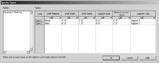
Now let's start to add the other header values and types in the type catalog. Be sure to save and test frequently:
,Shelf Material##other##,Shelf Width##length##feet,Shelf
Depth##length##feet,Support Inset##length##feet,Minimum Bracket
Space##length##feet,Support Type##other##
Type 1,Wood,4,1,0.5,2,Support 1
Type 2,Glass,6,1,0.5,2,Support 1
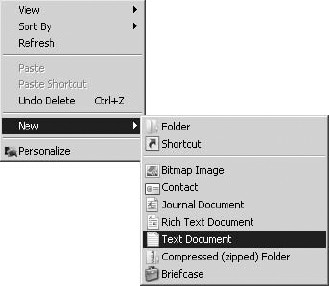
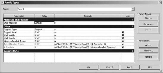
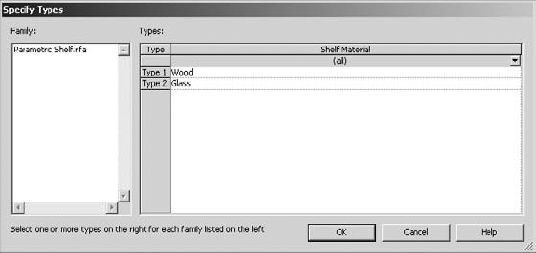
Figure 15.77 shows the result when you attempt to load the family into the project.
Now that you've created the type catalog in a text editor, you'll want to consider editing (or even creating) it in Excel. The important thing is that you'll need to import and export the catalog in a specific way.
For importing the type catalog, be sure you import the file as comma delimited. Open Excel and then select File
Select Comma as the delimiter in the second dialog box (Figure 15.79).
Now that you have your open catalog, you can fit the columns to the proper width and begin to add additional types. We've also added two additional types in this example (Figure 15.80).
It's important to save the file with the appropriate settings. Select File
Finally, be sure to test all the types in your type catalog in an empty project. You can do this by attempting to load all the types. You'll be given a warning if one of the types cannot be loaded (Figure 15.82).

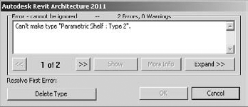
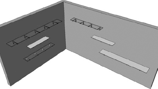
From left to right, Figure 15.83 shows Type 1 through Type 4, respectively. If you want to download the Shelf family and type catalog, look in the Chapter 15 folder on the book's web page for the files Parametric Shelf.rfa and Parametric Shelf.txt.

- Understand the Family Editor.
Before you start modeling a piece of content in the Family Editor, take a moment and think about how you expect that piece of content to "behave" in your project. Don't be afraid to model a first pass quickly. But also be thinking ahead with regard to how it might change. The role of the Family Editor isn't just an environment to model geometry; it also determines how the content that you create will behave in the project environment.
- Master It
Choosing the right template is critical. Some flexibility is allowed by allowing you to convert from one family template to another. But this is not always the case. Why would you want to choose a door template rather than a generic model template?
- Choose the right family template.
Some categories and parameters are more important than others. If you choose poorly, there's no backing up. You may simply have to start over and create the family correctly.
- Master It
Why are you concerned whether a family component should be hosted or not? What would happen if you select a hosted template and then decide it should be nonhosted (or vice versa)?
- Use testing parameters.
Reference planes, points, and lines are the "bones" of your component. Parameterize the bones, and the geometry will follow along. Be sure to test the parameter and reference relationships before you start assigning geometry.
- Master It
Why build, parameterize, and test the references first? Why not just model the geometry?
- Know why formulas are important.
Sometimes parametric behavior will depend on the parameters that directly control it, but often these parameters will be expressed as a relationship to something else.
- Master It
Why are formulas so important? Why not just create the parameters you need and then modify them as needed in the project environment?