
Creating extraordinary stairs and railings in Revit can be fairly challenging at times. Iterating and resolving your design idea is a lot like working in a spreadsheet, and designing in a spreadsheet without some graphical feedback can be fairly frustrating. On top of this, stairs and railings are often quite sculptural in addition to being functional, and there's just so much sculpture you can get to with the in-the-box functionality.
There's a lot that the Stair and Railing tools in Revit can accomplish that even advanced users don't always realize, but often it's the exceptions that trip people up. In this chapter, we'll cover some common scenarios of stairs and railings by using the tools in the usual ways and then also using them a bit creatively.
In this chapter, you'll learn to:
Understand the key components of stairs and railings
Design beautiful custom stairs with default toolset
Create elegant exceptions to the out of the box stairs and railings tool
Implement best practices
Designing and reiterating complex stairs and railings in just about any software application can be difficult. It's likely that you'll need to deeply understand the rules and constraints of the application; in effect, you're learning the language of the application. And in order to be able to communicate fluently in that language, you need to be able to think fluently. You almost have to be able to think beyond the individual words and begin to arrange whole ideas.
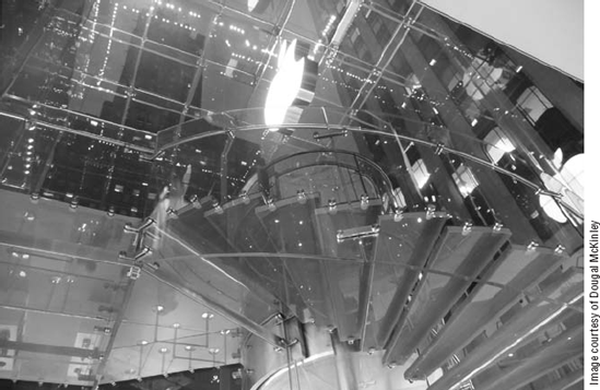
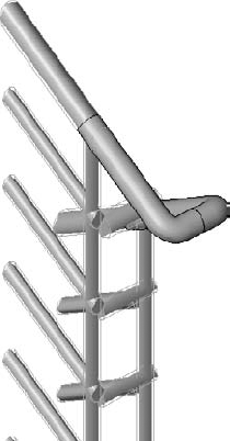
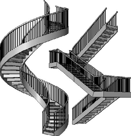
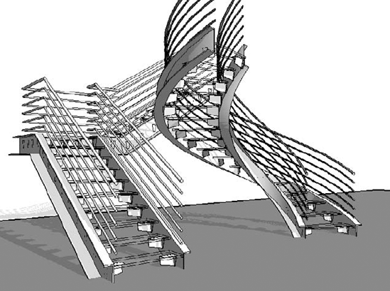
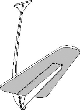
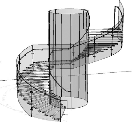
Regardless of how well you know how to use a particular application, you have to contend with imagination and creation of elegant and sometimes complex design issues. Sometimes stairs and railings may be quite straightforward and functional (think of a steel or concrete egress stair) where there's not a lot of room for thinking outside the box. But in many cases, stairs and railings are conceived as feature elements within a space. They'll be touched and experienced up close. They may be extraordinarily complex and sculptural'an almost "inhabited" sculpture (Figure 16.1).
When these two worlds collide—"amazing design idea" meets "perceived software functional limitation"—the result is understandably a lot of frustration for an entire design team, especially when you look back at the kinds of designs that were imagined and realized with simple paper and pencil. Computers were supposed to make this easier, right? Fortunately, you have a few options. Figure 16.2 illustrates the kind of stair that would challenge almost any 3D modeling program.

For example, you can use a generic modeling application such as SketchUp, Bonzai, 3ds Max, Maya, Rhino, and so on to model your stair and railing designs. Of course, stair and railing creation will require greater "fluency" compared with modeling other, more rectilinear objects. But there's a drawback. Even though you'll eventually come to understand the rules for creating and manipulating geometry in a generic modeling application, what still remains difficult is the design idea and managing design iteration. And although many of the generic applications on the market give you the "tools" to design complex form, they seldom give you the "rules" to manage the iteration of your design.
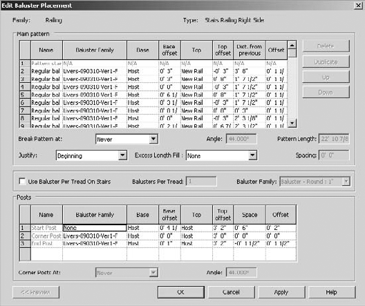
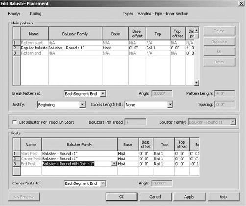
In Revit, the situation is often reversed: you'll frequently have the "rules" to iterate and manage your design. But the tools of geometry creation can be limiting at times. In other words, Revit is purpose-built for designing building elements and relating them to the rules of likely constructed relationships (doors associate with walls, furniture associates with floors, and so on). Revit isn't simply another "generic" modeler. The application is biased toward relationships specific to designing a building and maintaining those relationships as the design changes. But to make things a bit more complicated, there's another layer. Within the general language of Revit, there's a specific language to creating stairs and railings (Figure 16.3). The image below illustrates the baluster placement dialog for a very complex baluster condition.
From a design iteration standpoint, it's important that your building elements understand their relationships to other elements. They will also need to view, schedule, and maintain change appropriately. To accomplish this, you can use the inside-of-the-box stair and railing functionality in some interesting, innovative ways. But in many cases, the inside-of-the-box functionality will simply not suffice:
The functionality you require may not yet even exist. If this is the case, your options are pretty straightforward: you'll use other out-of-the-box functionality to create a reasonable, geometrically accurate representation of what you need. It won't be an "official" stair or railing. The upside is there may be some other desirable by-products when using non—stair and railing functionality. But the downside is that you'll have to be careful where the metadata ends up, particularly with regard to scheduling. We can almost guarantee that you'll have to use some filtering in your schedules.
The functionality that you require may be so indefinable that you might as well stop waiting for an out-of-the-box solution and start looking for elegant hacks. In other words, when the system of rules you're trying to create can't be defined by a system of rules, look elsewhere. When you expect the exceptions will occur more frequently than the rules, you're looking at quickly approaching diminished returns. The unpredictability of attempting to define the overall system isn't worth the effort.
Our approach has always been to try to find the solution that is both technically correct and aligned with the best intentions of the use of BIM (the life cycle of "cradle to cradle"). But at the same time, we believe that you should strive to take implementability into account. We have two simple approaches to determining when to use an in-the-box solution and when to think out of the box:
Is what you're trying to design best defined as spreadsheet or sculpture? If what you're designing can be described within a spreadsheet, then it's likely that you'll be able to use the Stair tool out of the box (like an egress stair). But if what you're trying to design cannot easily be defined within the confines of a spreadsheet (i.e., Stair Tool dialog box), it's likely you'll be working outside the box of the default Stair tool. This is because there are just too many exceptions and peculiarities to make using the default Stair tool worthwhile.
Just because your design might not fit within the confines of the Stair tool, it doesn't mean that you can't maintain a proper balance of project part/whole relationships when using other tools like the Family Editor. Remember that the Family Editor will allow you to maintain many relationships in a project by editing single elements and then reloading to maintain design iteration.
So in conclusion, it's important that whatever your approach, inside or outside of the stair and railing toolbox, your solution should maintain a balance of "efficient predictability." Design efforts are distributed across people and teams, and it's important that your approach is not so unique that anyone else would not be able to understand how to modify your design when it changes (and it will). And with that, let's move on to describing some essential parts of stairs and railings.
Details of what each of the instance and type parameters do and how they affect your railing and stair design have been covered in other books and the Revit user forums. This section is about the parts of the functionality that are important to being able to create interesting stairs and railings.
Note
The critical parts of a railing are the profiles, different kinds of balusters, and how they are placed within the definition of a railing.
- Profiles
You can have as many profiles per railing as you like (Figure 16.4), but you can't have more than one profile per family (RFA) file. And all the profile families need to be a closed loop—no gaps or overlapping lines allowed. Furthermore, all the profiles will be swept parallel to their host.
- Balusters
There are three kinds of balusters:
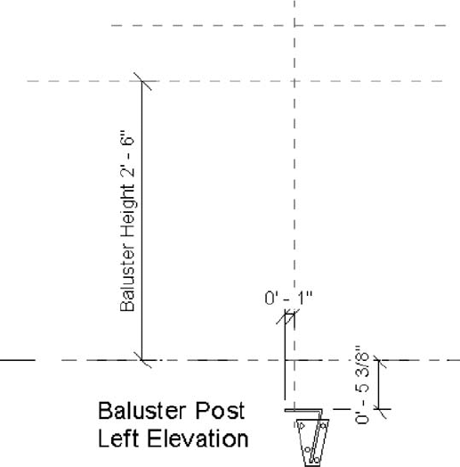
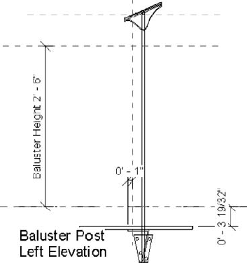
Baluster posts have built-in parameters to control the height of the baluster so that it can grow vertically (Figure 16.5).
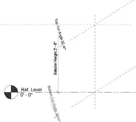
Balusters have parameters that control the vertical length of both the top and bottom of the baluster. But there are also reference planes that will control the angle of the top and bottom of the baluster. This is helpful for maintaining angular relationships to a stringer or handrail (Figure 16.6).
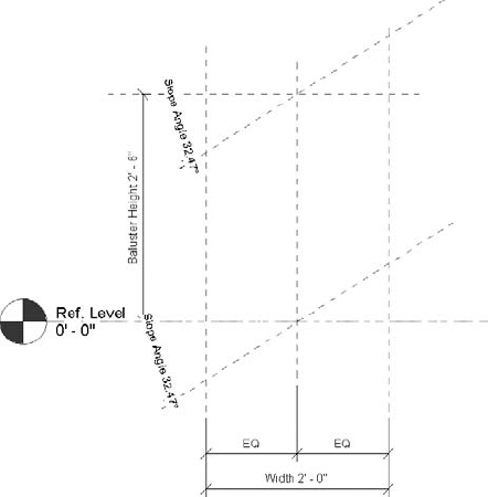
Baluster panels have controls much like the baluster. But there are additional reference planes to control the overall width of a desired panel (Figure 16.7).


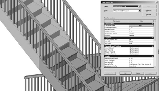
The railing profiles and all the different balusters come together to be controlled from a railing's Type Properties (Figure 16.8). Within this dialog box there are separate dialog boxes for the railing. For this particular example, we'll use the in-the-box Guardrail — Pipe family that's part of your standard Revit template.
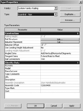
Selecting the Rail Structure option will show you all the profiles that are associated with this railing type (Figure 16.9). As mentioned earlier, you can have multiple profiles associated with a railing, but each profile needs to be a separate family file.

Selecting the Baluster Placement option will show you all the balusters that are associated with this tailing type (Figure 16.10). As you can see, there are options for the main pattern, the posts, and an option for how the balusters will be used on stairs (Figure 16.10).
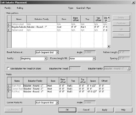
The Main Pattern section of the dialog box is where you would assemble all your baluster types and then space and host them accordingly. You can also decide how you want the pattern to repeat (or not repeat) itself at ends of sketched line segments.
The Posts section is used to specify which baluster is used at start, corner, and end conditions (and the frequency of corner posts).
That's about it with regard to the properties of railings; we've just covered the most important features necessary to create great railings using both in- and out-of-the-box techniques. Now let's discuss the important and fundamental parts of stairs.
The critical parts of stairs are the nosing profile, stringer, tread, and railing. Railings are allowed unique conditions when used with stairs.
- Nosing Structure
This is one closed loop that can be associated with the front and both sides of the tread.
- Stringers
The default stringers can only be rectilinear in form and may only be placed on the left, right, and middle of the stair. There may be multiple middle stringers.
- Treads
Basically you can control the depth and the thickness. The actual shape of the tread in plan is controlled in Sketch mode. Keep in mind that when changing the thickness of the tread, the top of the tread is maintained.
- Balusters/Railings
There is an important override option that allows you to specify the number of balusters per tread when the railing is used with stairs (as well as specify the baluster).
Now that we've covered the key components of stairs, let's start to investigate railings using techniques that are more common to Revit. Once you understand these rules, you'll better understand how and why to "stretch" them to create more complex configurations.
We consider in-the-box techniques to mean using the functionality in interesting and useful ways and leveraging intended functionality. But keep in mind that the metadata may or may not remain associated with the category of element that you're creating. For example, you can use the Railing tool to create railings, but you can also use it to distribute repetitive elements along a path that may not be railings at all. As a result, your schedules will need to be watched carefully so that certain elements are properly counted and undesirable data will be ignored.
Using a 3D pattern to represent geometry is not a new idea in Revit. We use pattern files to represent ceiling tiles, masonry patterns in walls, and other host elements. Using 3D patterns is a great way to go easy on your computer as well. And there are a couple of places where using model patterns is useful for creating specific types of railings.
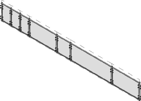
First, indicating wire mesh panels for railings is not that hard, and it'll keep you from dealing with unnecessarily high levels of detail. The technique is also great when the wire mesh panels are curved (Figure 16.11).

The technique is simple and can be accomplished in just a few steps:
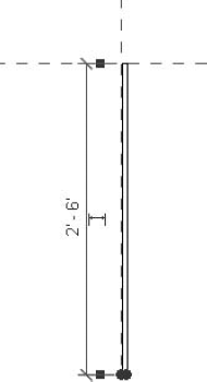
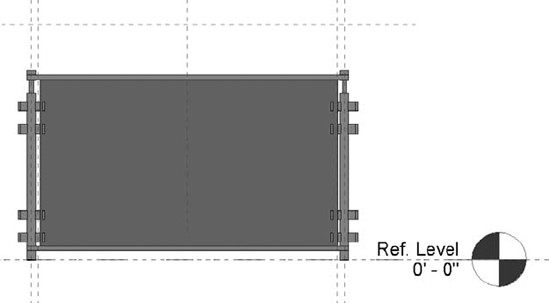
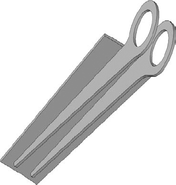
You'll need a piece of geometry to represent the "zone" of the mesh. This can be easily created in the Family Editor as a profile family. In this case, the profile is ½" x 2'-6". Take care of the insertion point (Figure 16.12). This is important to keep the top of the profile properly associated with the top handrail when used with stairs.
Save the family and load into a default project. For this exercise, let's start with a simple railing of Railing — Handrail Rectangular. Duplicate and rename it to Railing — Wire Mesh, and then we'll modify it.
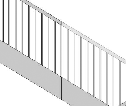
Change the baluster placement from 0'-4" to 4'-0". This will give you plenty of space between the balusters and make room for the wire mesh (Figure 16.13).
Now let's edit the rail structure. Duplicate the existing handrail and change the elevation. Then add another region and associate it with the wire mesh profile that you previously created (Figure 16.14).
Finally, you'll need to create a new model pattern (Figure 16.15) and associate this pattern with the profile of the wire mesh. For this example, use a 2" x 2" crosshatch pattern at 45 degrees. And don't forget to set the Transparency value for shading to 100%.


When you finish, a portion of your railing should look like Figure 16.16.

Now go ahead and create some stairs. When you're finished, swap out the default railing for your newly created wire mesh railing (Figure 16.17).

Keep in mind that this technique is great for indicating fences with vertical or horizontal battens (rather than building them out of actual geometry). This file is also available for download from the book's web page (www.sybex.com/go/masteringrevit2011) in the Chapter 16 folder; look for the Wire Mesh Railing and Stair.rvt file.
Unfortunately, Revit doesn't yet allow components to be quickly and easily distributed along a user-defined path. In some cases you could use "line"-based families, but these don't work in curved conditions. Having a technique that works in both straight and curved conditions is probably the best option. So in the meantime, we think you should consider using the Railing tool to distribute elements along paths.
When using railing functionality to distribute elements along paths, keep in mind these three rules:
You'll likely want to nest your family into a baluster family template (rather than creating it directly as a baluster). This is because the existing parameters in the baluster family will often cause your geometry to fly apart if it needs to move up and down as a single element.
Don't expect your nested element to schedule or tag. If you need the elements to schedule or tag individually, you probably want to place them individually (or use another technique like a line-based family).
Don't share parameters of nested families in an attempt to schedule. It won't schedule'it'll break.
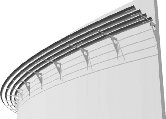
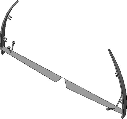
In some cases, you'll want the railing family to have associated profiles, like the shading device in Figure 16.18. The railing profiles are used to create the shading fins, and the balusters are the support elements.
But railings don't have to contain handrail profiles. Follow these steps to delete a railing profile:
Set the Top value of the railing to Host.
Give the baluster a positive Top Offset value.
Delete the railing profile. This hosts the baluster by the host rather than the railing profile. Picking any of the balusters will allow you to edit the sketch. But the profile of the railing won't be seen until you select any one of the elements and edit their associated sketch.
Using railings to quickly and evenly distribute components along a path is great during design and allows for quick iteration. Outdoor elements are particularly appropriate for distributed placement, like a lampposts (Figure 16.19). In this example, a lamppost has been nested into a baluster family.
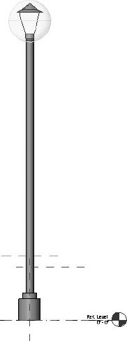
Once this lamppost has been nested, you'll be able to create a custom "railing" with the lamp designated as the "baluster." This will allow you to quickly and easily distribute lampposts along a sketch at very specific intervals that can be modified as a parameter. So for example, if the lamppost was originally distributed on 60' centers, you could very quickly redefine it to occur on 40' intervals (Figure 16.20).
You can use this for any repetitive elements that must be placed on center and evenly distributed along a path. Other uses might include pipe bollards and outdoor planting.

Even a design pass at light rail tracks (including railcars) can be distributed along paths (Figure 16.21). In this case, the rail sleepers are balusters and profiles are used to create the rails and the rail bed. The monorails are easy too. The vertical supports and railcars are balusters, and the suspended track is the rail profile. This file can be downloaded from the Chapter 16 folder; look for the Monorail and Railway Railing.rvt file.

Railings outside of the box are meant to be railing-like, geometrically speaking, but they're not created with the Railing tool. Usually this occurs when the railing is a small, unique, or highly repetitive element.
Generally speaking, maintaining order in Revit projects is often about managing repetitive relationships. These repetitive elements may be managed by creating family components, groups, and even separate Revit files. For railings, there is an obvious choice: create the railing, then create a group of the finished railing and then copy that group throughout your finished project.
Unfortunately, it's often faster to manage and update hundreds of components than it is to update hundreds of groups. The railing may also be prefabricated and installed onsite as a single component, perhaps filed under the Revit category of Specialty Equipment. If you decide to use the category of Specialty Equipment, keep in mind that the category won't cut; you'll always see a projected elevation. So, choose a category (like Generic Model) if you need to see the family cut in section.
What kind of highly repetitive railing conditions are we referring to? Sport stadiums, theaters, hotel balconies, apartment buildings, and so on all have railing conditions that are highly repetitive. Railings modeled as a singular component in the Family Editor are perfect for these kinds of situations where only a few family components can cover hundreds of conditions (Figure 16.22).

Custom handrail joins are known to frustrate Revit users. But again, if modeled in the Family Editor and associated with the railing, it's a challenge that can often be easily overcome. What's important is that you'll need some context to model your custom condition. So go ahead and model the context of what you need as a starting point:
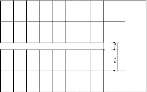
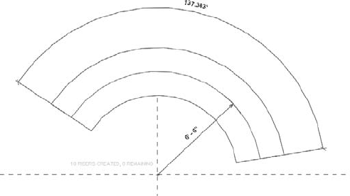
Open a default template and sketch a stair with dimensions shown so that there's really no reason to have a railing between the two runs, but the railing should still be continuous (Figure 16.23). Note that there is only 6" separating each run.
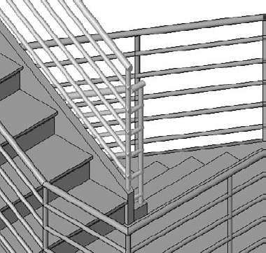
Associate the Handrail — Pipe railing with the stairs and the problem is obvious: how to properly model the join between the railings (Figure 16.24)?
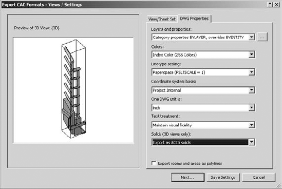
In order to model the join between handrails, it'll be helpful to have some context. Activate a section box around the desired portion of the handrail. Then export this 3D section (Figure 16.25).
Since the handrail join will be part of your baluster, go ahead and duplicate the default round baluster family and name it
Baluster - Round with Join.rfa. Now import this 3D context into your duplicate baluster family. Also, before you start to model the connections it may helpful to create some reference planes (Figure 16.26).If modeling in a nonstandard 3D view is a challenge, try to model what you're creating in a standard 3D view and then rotate your component into place. You'll still be able to edit it afterward. In this case we've modeled half the join and then mirrored the other half (Figure 16.27) in context with the portion of the exported handrail.
Once you're done modeling the connection, you may either delete the exported context or deselect its visibility settings in the Instance Properties of the imported file.
Back in the project environment, you'll want to delete the portions of the handrail sketch that are shown in Figure 16.28 as highlighted in blue. Keep in mind that the lower portion of the railing will be completed as a separate, hosted sketch. You won't need to model the railing connecting the upper and lower runs. Finally, the lower, hosted railing run will be the default Type Baluster — Round, not the custom baluster that we are making.
Duplicate the remaining portion of the inner handrail and rename to Handrail — Pipe — Inner Section. This will differentiate it from the default Handrail — Pipe. Now you can edit the value of the end post to the baluster family that we've just created (Figure 16.29).
Through a system of careful measurements (as well as a bit of trial and error), you'll want to elevate, rotate, and finally nudge the handrail join portion of the baluster family until it's in the correct position with regard to the upper and lower handrail runs (keeping in mind that the lower run is a separate sketch). Just remember to reload the baluster family into the stair project to make sure that your adjustments are correct.


After a few moments, you'll end up with a custom connection, as shown in Figure 16.30. The great thing about this technique is that it works with multistory stair conditions. You can download the completed project in the Chapter 16 folder at the book's web page; the file is named c16 Custom Handrail Join Project.rvt.

Although the three-run stair has to do with stairs as well as railings, we'll go ahead and cover it here. You can't have overlapping sketches when using the Railing or Stair tool, so you're obviously going to have to create two separate sketches. This is where most people run into problems: they divide the sketch at one of the landings.
We've found that a better technique involves breaking the stair and railing in the middle of the second run, not at the landing. Here's how:
Open a new project using the default template. Then open your South Elevation and create a new Level 3, as shown in Figure 16.31.
Return to Level 1 to start your stair sketch. You'll notice that the moment the sketch starts, you're expected to create 18 risers to complete half of the three-run stair'which means that each run will be 12 risers (36 total risers divided by three runs). So sketch your first stair with 12 risers, then a landing and another 6 risers (Figure 16.32).
Now mirror the stair at the end of the second run. Change the direction of the second run so that the landings meet correctly.
Modify the Instance Properties of the stair to start at Level 2 and finish at Level 3, as shown in Figure 16.33. You'll also notice that there's an "extra" tread overlapping the landing. Not to worry'we'll fix that in a moment.
Go to the default 3D view and you'll notice that the second run doesn't meet the first run properly (Figure 16.34). That's because the stair you just mirrored starts with a riser (which you don't need).
Go to the stair properties of the mirrored stair, and duplicate the stair type. We're going to change the Type Properties of the second run.
Change the Extend Below Base value to —1'-6" and deselect the Begin With Riser option (since we already have a riser, from the end of the first run of stairs).
Click OK. You'll be given a warning that the actual and desired number of risers are different. Ignore the warning. Now return to Level 2 and edit the sketch of the second stair. You'll notice that you need another tread to complete the stair.
While in Sketch mode, simply press and drag the run line of the lower run to add an additional tread. Then move the entire sketch over 11" so that the treads between the end of the first stair and the beginning of the second stair don't overlap. Finish the sketch. This will complete the connection between the first and second stair (Figure 16.35).
Duplicate the Type Properties of the upper railings. Then edit the Type Properties of the lower railings so that the Space value of End Post is 0. Set the Start Post value of the upper railing to None. Set the Justify value for the Baluster Placement of the lower railing to End and the same value for the upper railing to Beginning. You'll get the result shown in Figure 16.36.


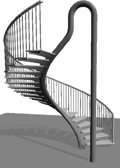
You can use this same process to create a spiral stair that is continuous and would otherwise overlap in Sketch mode (Figure 16.37). You can download the stairs in this example in the Chapter 16 folder on the book's web page; it's named Three Run Stair.rvt.
The most challenging of railings often require exceptions and the ability to manually locate balusters or panels that are not part of the overall railing definition. If you were to try to define each of these exceptions as a different railing type, your project would have an overflow of railing types. This can be pretty easily accomplished, but not with the Railing tool.
By using the Curtain Wall tool, you'll be able to create railings by modeling the balusters and panels inside the Curtain Panel family template (Figure 16.38). The other nice thing about this technique is that this "railing" will contain space since it's really a wall. That makes this perfect for mezzanine conditions that require room or space calculations'certainly more efficient than creating redundant room separation lines!
Start by creating a single panel in the Curtain Panel template. The family may contain not only the panel for the railing, but also the balusters. Once you load this panel into your project, you can create Curtain Walls with predefined panel widths (Figure 16.39).
But since curtain panels allow you to unpin predefined grids (as well as create other grid locations) you'll be able to quickly and easily make exceptions to the rules that you previously defined (Figure 16.40).

When you're creating railings as curtain walls, be sure to filter your schedules accordingly. If you want to download this example project, it's in the Chapter 16 folder and is named Curtain Wall Railing.rvt.
These in- and out-of-the-box techniques should give you some great ideas for making custom railings faster and more interesting than you could ever have imagined.
Using in-the-box techniques means you're using the built-in functionality of the Stair tool to create conditions that may not have been originally intended by the factory. Sometimes this is done to overcome a limitation in functionality. But it most cases you'll be using the functionality to create conditions that are common in complex stair conditions.
As for the out-of-the-box techniques, sometimes there's just no way to anticipate every unique and sculptural design condition. In these cases, we'll show you techniques that aren't exactly using the Stair tool as designed. But the results will geometrically resemble stairs (and their railings).
Note
You shouldn't overlook the nosing profile as a device for creating interesting shapes that complete the tread, because the shape of the nosing is not limited to traditional nosing profiles. Any shape that needs to extend beyond the face of the tread is OK. Just remember that you're limited to a single profile per tread and stair run (Figure 16.41). You'll also want to pay particular attention to the insertion point of the nosing profile because the intersection of the reference planes coincides with the top of the tread and the face of the riser.
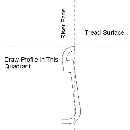
Figure 16.42 shows an example from a real stair that was designed to have each tread fabricated from a single plate and then rolled to form the face of the riser above it. Then each of these treads can be welded behind the lip of the tread above it. It's a fairly elegant idea that can be accomplished by using a custom nosing profile to create the appearance of a continuous tread (Figure 16.42). Look closely and you can see where the actual tread ends and where the nosing profile begins. But don't be distracted by the lines since they can be hidden (if necessary) when you're creating the final details.
Make sure that if you're using a custom profile to represent both the nosing and the riser that you set Riser Type to None. If you don't, the profile won't be assigned correctly; it will overlap the default riser. Figure 16.43 shows the final stairs using the custom profile. As for the custom railing conditions, we'll get to that later in this chapter. If you want to investigate this stair further, it's in the Chapter 16 folder and is called Henrys Stepp.rvt.

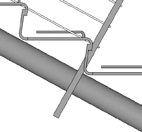
Next, let's move on to default stringers in Revit. These are good for creating a number of standard residential (wooden) or steel (commercial) conditions. What's important is that the default stringers in Revit can only be rectilinear and may be positioned to either side of the stair (left and right) and the middle. If you want a custom shape, you're out of luck if you're using default stringer. So don't! When you want to create a custom stringer profile (left, right, middle, or otherwise), simply use the Railing tool (Figure 16.44). The stair will host this railing containing the custom stringer profile (or just the custom profile, with no handrail).
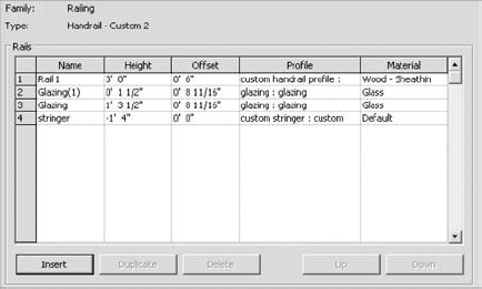
Notice in Figure 16.44 that the last profile is not really part of the traditional portion of the railing. Instead, this profile is used to indicate a custom stringer profile (Figure 16.45). But it's been assigned to the railing in order to maintain a particular relationship to their stairs.

In Figure 16.46, we've isolated the railing from its stairs in order to illustrate the finished railing: the handrail, two glazed and continuous panels, and the custom stringers.

This railing with a custom stringer profile is perfect for a multitude of stair conditions, straight or curved or even a combination (Figure 16.47). This technique finishes off the stair nicely and exposes the structure in interesting ways.

Although the stringer usually occurs to the left or right of the treads, this is certainly not always the case. In some situations you'll want to create a middle stringer using a custom profile. Just remember that this will be a railing that will be hosted by the stair and may not even contain a handrail, just the profile for the stringer (Figure 16.48). In this case, the railing is still being hosted by the stairs'it's just that there's just not any railing geometry above the tread.

Straightforward tread shapes can be pretty boring at times, so let's move on to custom tread conditions. In situations where you need to be a bit more inventive, you're going to create a custom baluster. This technique can either create a custom support element for the default treads or it can indicate the actual tread.
But instead of the baluster being vertical, it's going to be horizontal. This horizontal baluster will be used in conjunction with the default tread. This baluster may even completely envelop the tread.
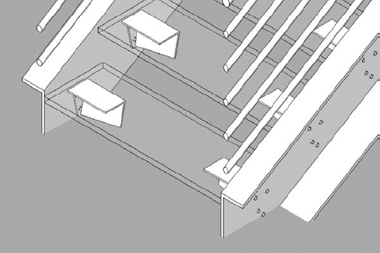
First, we need to discuss a few rules for creating an interesting tread support for the default tread (Figure 16.49):
Not every baluster needs a railing. If your baluster support isn't going to be a part of the "real" railing, just create another "railing" that is hosted by the stairs. Sketching another path for your custom railing that only contains the tread support baluster can accomplish this in a few steps. Another technique is to copy an existing railing, then paste it to the exact same location and change the type to your custom supporting baluster.
The Baluster Family category needs to be used for the component that will act as the tread support. Otherwise, it can't be associated to the railing.
If you have a complex support element, it may be helpful to model the desired support element as a generic family. When you're finished, nest this generic element into the baluster family. You may want to do this because the baluster templates have hard-wired reference planes and parameters (which is fine if you're making a baluster that needs to geometrically flex). But in this case, we've found that these reference planes and parameters may cause your baluster to fail when you load it in the project as a result of these parameters flexing. By modeling the geometry elsewhere and nesting it, you avoid this hassle since it moves as a single component.
Designating the level of detail is crucial. Assigning Coarse, Medium, or Fine as well as Orientation leads to much faster graphics regeneration, view panning, and model rotation. So if you're nesting one component into another family, the detail that you're assigning at the deepest level will be respected through nesting (Figure 16.50).
Once the component is complete, you can nest it into a baluster template, as shown in Figure 16.51. If necessary, it's also possible to parameterize the dimensions in the nested configuration.
The completed stairs are shown in two different configurations in Figure 16.52. Many configurations are possible once you correctly define a single stair type. If you'd like to investigate this stair more closely, go the Chapter 16 folder at the book's web age and download c16_Angled_Support_Stair.rvt.
Note that a custom baluster support might be modeled to contain the real balusters that are intended to support railings. This can simplify and shorten modeling time. In the example shown in Figure 16.53, the baluster support geometry also contains the railing elements on both the right and left side. If you want to examine this stair more closely, it's in the Chapter 16 folder and is called Support Tread.rvt.
The previous support baluster can be brought together with a custom profile for the center stringer, handrails, and glazed panels (Figure 16.54). You can download this example from the Chapter 16 folder; it's called Center Baluster Support.rvt.
Once you've begun to experiment with creating balusters as tread supports for stairs, you'll notice you have options for making more complete and finished conditions.

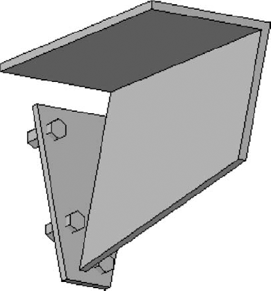
Start and end posts are useful and can help complete the structure of your custom railing and baluster system, particularly if you want to properly anchor and connect your custom stair and railing. The example in Figure 16.55 uses only start and end posts to anchor the custom railings and stair structure. It builds on the previous example of using a baluster as a support element for a tread.
To finish this stair, we need to create start and end posts that anchor the stair. As with the previous handrail join exercise, you'll want to model the bulk of the custom stair with the custom railing. Then you'll export the stair parts for importing into the baluster template (or generic model template that will be nested into the baluster template).
Figure 16.56 shows the results after the start and end posts are modeled.
When it all comes together, the results can be elegant and interesting (Figure 16.57). All of this is available through the default Stair tool. You can download this stair from the Chapter 16 folder; it's called Tube Stair.rvt.


Now let's go one step further. There's no reason that the baluster support element needs to exactly conform to the shape of the tread. And there's no reason that the support element can't contain the actual baluster that is intended to support the handrail.
Take a look at the support element in Figure 16.58. Not only does it contain the support element, but the support element has been modeled to exceed the shape of the tread that will be modeled by the Stair tool.
Keep in mind that we've modeled the support element as a generic model and then nested it into a baluster post template (Figure 16.59). Again, this keeps the baluster together so it's not affected by the built-in reference planes and parameters.
Once this custom baluster post is loaded into the project, simply associate it with the stair and its railings. Remember to select the One Baluster Per Tread option. When finished, the default tread is simply an inlay to the more complete tread support (Figure 16.60). In more complex conditions, it may be desirable to envelop the entire tread with the support geometry. This will allow you to create complex tread shapes that are not dependent on the default tread and use the functionality of the stair and Railing tools to properly locate, rotate, and elevate each of your custom treads. If you want to examine this stair further, check out the file Curved Tread Support.rvt in the Chapter 16 folder.
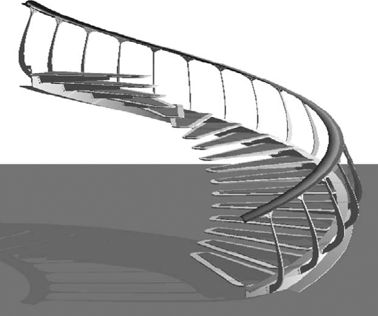
Figure 16.61 shows an example using this technique. The tread support elements have been modeled using blends in order to sweep under the metal plate while changing direction from vertical to angle. This will accommodate the angled pipe rail that will support the stair.

Treads come together in a particularly interesting stair and railing configuration. There is obviously a more conventional outer railing for this stair. But the inner railing doesn't have any elements that occur at hand height. The entire inner railing exists to support the baluster supports (that in turn support the default treads). The end post is being used to anchor the entire structure through the second level. You can find this example, Highlights.rvt, in the Chapter 16 folder. Figure 16.62 shows the finished stair. Note that the large structural element is actually a baluster that's been designated as the end post.
As we approach out-of-the-box techniques, the goal is to create stairs that may not fully adhere to strict interpretation of BIM in that the metadata may not correspond to the geometry. But this is usually the only option to complete a design where there's no in-the-box technique. At least you'll be confident that your project will be properly coordinated from a geometric and documentation point of view.
Just be a bit more careful when you use these techniques. The metadata—the information part of BIM—isn't being coordinated properly. So you'll want to take particular care with regard to tagging and scheduling.
Let's start with the stair from the previous section (Figure 16.63).

While the railings on the left side of the image seems pretty straightforward, the curved railing on the left may seem a bit challenging, the three balusters inside the curved element are perpendicular to the run of the stair, and the cable starts and stops before completing the run (which is the default condition). However, this is actually accomplished in a few easy steps.
This example nests geometry modeled in the generic family template and then nests that geometry into a baluster post template. The baluster is then assigned as the start post to create the entire railing. The nice thing about using the start post is that whenever you create the stair, the "railings" are automatically added, even if you create a multistory stair condition.
Once again, there are a few steps to follow, which by now should be rather familiar.
First, model what you can with the out-of-the-box tools. Even if you can only model the treads, this will help give you context to the rest of the system; then export the treads from a 3D view and import it into a generic model family. In this case, everything that can be modeled as the stair is shown in Figure 16.64.

After exporting this stair in 3D and importing it into the Family Editor, you can model your design in context with exactly how it will be used. Figure 16.65 is the resulting form that will be used assigned to the stair's railing as a start post.
This is a valuable technique for creating complex and difficult-to-predict railings for stairs. The important part of this technique is to use the out-of-the-box Stair tool to model whatever is easily possible for context. Once again, here are the steps:
Export the stair in 3D.
Import the exported file into a generic model family.
Model your complex railing design in context with the imported 3D (keeping in mind that reference planes are helpful).
Nest the finished family into a baluster post family.
Associate this baluster family as the start post for the railing.
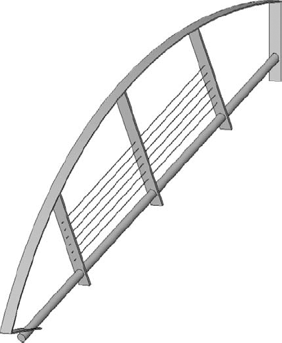
Here's another example of using this technique to overcome and otherwise complex condition that simply could not be created using the default Stair and Railing tools. The stair in Figure 16.66 is modeled with the default tools: Stair, Baluster, and Railing. This creates all that is necessary for modeling the wire cable net that will be used to complete the stair.

Once this geometry is exported, it's ready to be used as context for modeling the cable net that will be assigned as the start post for the stair (Figure 16.67). If you want to study this stair and railing further, check out the file Cable Stair.rvt in the Chapter 16 folder.
Now we'll talk about other challenging configurations. In many cases, it's not the parts that make up the entire stair that is the challenge. Often it is the overall configuration that vexes people (like creating the three-run stair we previously discussed).
A solid spiral wall to be used as a railing or a support element can easily be created in the Family Editor and then associated with the stair as a start post. Of course, this geometry could also be created as an in-place element. But then you'd lose the advantage of being able to quickly and easily relocate the stair in your project (or create a multistory condition).
In Figure 16.68 you can see the default tread with a baluster being used as a support element. What's interesting about this configuration is that rather than being configured as a circular stair, the path is made of two concentric arcs.

Rather than create this as an in-place family under the stair, we'll model the swept blend as a baluster post in order to associate it with the beginning of the custom baluster. In order to make sure that we have the path exactly right, we'll copy the path of the custom railing that's associated to the support baluster (Figure 16.69).

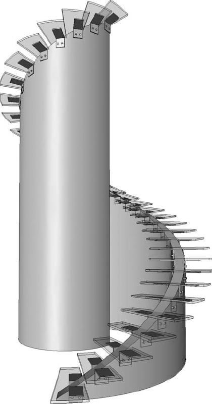
Now you can use this path as you create each of the blended sweeps (creating only one swept blend per path). In this case the blends are being modeled so that there's a 3" gap between the undersides of the default treads. The final swept blend in shown in Figure 16.70.
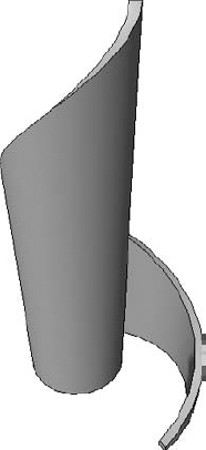
Figure 16.71 shows what you get when it all comes together. The swept blend has been created in a baluster template. This baluster is then loaded into the project environment and associated with the railing that contains the overall support baluster (Figure 16.71). This is also useful if you have to create walls that need to follow either side of a stair. If the condition exists only once, you may opt to create this in-place.
But if it occurs more than once or might be rotated and relocated (as well as occur on many levels), we recommend that you create this as part of the stair and railing definition. Then it'll be easier to maintain relationships throughout the project. To investigate this stair, download the Concentric Stair.rvt file from the Chapter 16 folder.
Another condition that results in a lot of confusion is creating a circular run that ends aligned from where it begins. This is also quite easy to accomplish once you understand the proper steps.
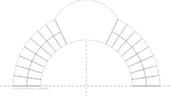
First, as you start to create the circular run, you'll notice the number of required treads. In the case of the default stairs and default template, 18 risers are required. Start by creating half that number, or 9 (Figure 16.72).
Once you've created the first half of the stairs, rotate and mirror the nine risers (Figure 16.73).

Now here's the tricky part: sketch the remaining boundaries manually. In other words, don't elect to finish the run and think that Revit will automatically complete the boundary for you (which works with more conventional configurations; see Figure 16.74).
Now you're ready to finish the stair sketch with the confidence that the end of your stair is aligned with where it begins (Figure 16.75). To study this stair, download the Curved and Aligned Stair.rvt file from the Chapter 16 folder.

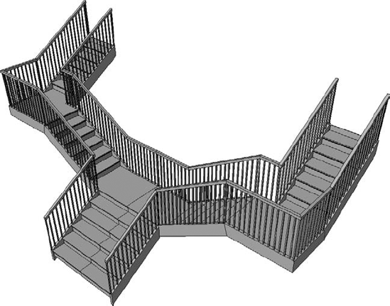
Another type of stair that creates a lot of confusion is a stair with split runs. In other words, it may start as one run but then it splits (typically at the landing) and becomes two separate runs. The challenge is that many users will create the first stair as a complete run. Then they will create a shorter run from the landing to the second level. If only it were easier... Well, it is!
Simply create half the stair and then mirror the results. Although this might create a line along your first run, the line can be hidden, and in the long run, the stair will be easier to modify and update. So let's get started:
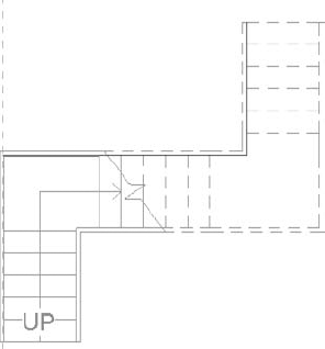
The entire stair is going to be 3'-0" wide, but the first run is going to be 6'-0" wide. The shape of the sketch is shown in Figure 16.76.
Once you finish the stair, edit the railing as shown in Figure 16.77. This will get rid of the railing through the middle of the landing and between the first run.
Now finish the stair and mirror the results. That was easy enough! But now you have to get rid of the default stringer that associated with the stairs (Figure 16.78).
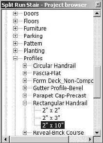
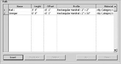
Edit the properties of the stairs and remove both the left and right stringers. Then create a profile of the same dimensions and associate it with the railing. But rather than create a new profile, make things easy on yourself by duplicating the Rectangular Handrail profile that you already have in your project. Be sure to also modify the Type Properties of the handrail profile (Figure 16.79).
Now associate this profile with the handrail that is associated with the stairs, as shown in Figure 16.80.


The custom stringer profile now exists as part of the railing definition. Now you have a split run stair that can be easily modified if the design changes (Figure 16.81). This stair can be downloaded from the Chapter 16 folder; look for Split Run Stair.rvt.
Now let's put it all together. When it comes to feature stairs, few stairs are as immediately recognizable as the glass stairs and walkways that have been designed for Apple by Bohlin Cywinski Jackson (Figure 16.82). Although these stairs seem incredibly challenging, there's very little about the Apple stairs that can't be modeled out of the box!
Even though the stairs are very sculptural, there are quite a few repetitive relationships that are easily identified and defined. Of course, what doesn't strictly conform to the rules of the Stair tool will have to be modeled elsewhere. First, let's model the treads and landing. We're assuming some dimensions since we don't have the actual drawings or measurements to work from: 2" thick, 6'-0" wide, and a 4'-0" interior radius (Figure 16.83).


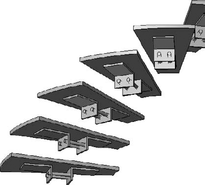
A small support "pin" is used to support the treads. One pin per tread supports the inner portion of the tread, but two pins per tread support the outer portion (so right away we'll have to create two separate handrail types for the stair). Figure 16.84 shows the pin family.
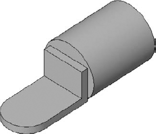
With this in mind, we're able to place the pin as a baluster after modeling it as a generic model and then nesting it into a baluster family template (not a baluster post), which will allow it to conform to the elevation of the landing. Since the pin is so small, it is also given a "fine" level of detail assignment so it doesn't show up unless the view is set to Fine.
As just mentioned, two handrail types are needed, since they will host different baluster definitions. The inner handrail has one pin support per tread, whereas the outer handrail has two pin supports per tread (Figure 16.85).

As for the start and end posts, two families are needed: one for the start configuration and another for the end. They include the horizontal extension beyond the end of the railing sketch. Once you've added these posts, the stair really starts to come together (Figure 16.86).

This concludes the portion of the stair that can be modeled out of the box. Export this 3D context for the remainder of the stair, which will be modeled as a generic family and then nested into a baluster post and assigned as a start post. There's a third railing in this stair (which contains no railing profile). This "invisible" railing is hosted by the stair and creates the remaining elements, as shown in Figure 16.87.
Two swept blends form the upper and lower glazed and curved panels, and a regular sweep forms the panels at the landing. At the same time, a single extrusion forms the center, glazed cylinder. When all this geometry is modeled, a single void (in plan) is extruded vertically and creates all the discrete panel separations at one time.
The panel supports and the actual balusters that will support the railing are modeled elsewhere and then nested into this family. This approach will allow the object to be quickly updated from a single location. Keep in mind that the handrails in the project will be used to host the baluster "pins" (one or two per tread); the actual handrail supports will be nested into this family. Each panel has a single baluster element (Figure 16.88).

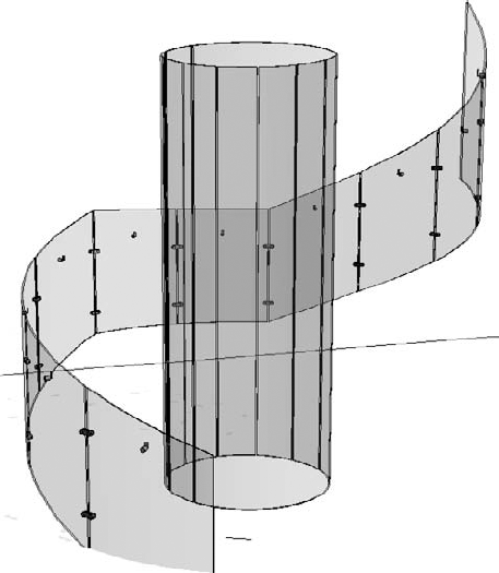
Now you're ready to associate this baluster post with a center railing (which contains no handrail). A couple of details are shown in Figure 16.89.

Figure 16.90 shows the finished stair. Yes, there's a lot more to the stair than this: the platform, elevator, landing, and so on. At the end of the day, there's nothing to keep you from modeling the entire stair in the Family Editor and then placing it in the project as a generic model. In some cases, this is exactly the kind of modeling control that complex and sculptural stairs need. Are they stairs? No, they're probably more like inhabitable sculpture. And trying to design sculpture in a spreadsheet is harder than just modeling what you want in the Family Editor. But what about "parameters," you ask? Well, sometimes defining the parameters takes more time than making the change manually in one place and then reloading the results into your project. If you're interested in downloading this stair, it's in the Chapter 16 folder; look for Apple Stair.rvt.

Here are some best practices to consider with regard to creating complex stairs and railings:
Don't forget to nest your family components whenever possible and appropriate. This will keep the component together when associated with some other template that contains hardwired parameters and reference planes. It'll also save you and your team a lot of time during design changes and iteration.
Don't struggle with creating the stairs in this chapter. If you get stuck, you can download the sample stairs from this chapter and use them for a starting point when creating your custom stair. Just remember it's usually easier to build and test a custom stair or railing in a sample project first. Then copy and paste or use Transfer Project Standards to get the custom stair or railing from the test project to your actual project. Download sample files for this document at the book's web page. You'll probably want to copy your custom stairs and railings in an easy-to-access project that contains row upon row of finished and polished examples (since they can't be kept as family components).
The level of detail and visibility is crucial if you care about graphic refresh times and printing. As you model the components of your custom stairs and railings, assign appropriate orientation and level of detail (Coarse, Medium, or Fine). You'll notice a difference when you pan and rotate your model.
Take care to filter schedules. Using a curtain wall as a railing may have certain advantages, but you also want to make sure that your schedules are accurate.
Overall, be careful when reaching into your bag of tips and tricks! You need to weigh the cost of implementing a new process against the cost of doing what's familiar. Make sure that you're maintaining a balance between predictability and efficiency. There are frequently two extremes that you need to avoid:
The first error involves doing what is highly predictable but not very efficient. In other words, most people will grasp the solution that you intend to implement; they'll fully understand the technology and technique. But they'll also quickly realize that managing design changes and iteration will be highly manual and time-consuming. And the rest of the team will doubt your leadership and understanding of the technology and processes.
The second extreme is that you'll manage to create a highly efficient uber-solution, but one that is not very predictable to the project team (much less a recently introduced outsider). In other words, it'll almost be too efficient. Only you or perhaps a few team members will understand what you've created. Everyone else on the team will resist making any changes to your creation out of fear that they'll break it.
So, what's important with creating interesting and innovative stairs and railings is that you manage to strike a balance between these two extremes. Just remember these four simple characteristics:
Beneficial Not just to you, but to the project team
Efficient Implementation and changes that are fast and predictable
Elegant Understood by the team and by any last-minute new members
Repetitive Can be used on many projects
If you can't remember these guidelines, the handy acronym of BEER should help. When you are not sure which solution is the best one to follow, your team will tend to gravitate to whatever allows them to have a beer at the end of the day.
In other words, whatever allows them to decompress, reenergize, and come back to work the next day refreshed, focused, and enthusiastic will ultimately win out. And keep in mind that this principle isn't just important to stairs and railings or Revit or BIM; it's important to having an interesting life.
- Understand the key components of stairs.
Having a complete understanding of the components of stairs is important. You don't want to set about breaking the rules until you understand how best (and when) those rules can be broken.
- Master It
What are the essential parts of stairs?
- Know when not to use railings.
From model patterns to geometric intricacy, there's a lot that can be created with the Railing tool. When this doesn't work, look to the Curtain Wall tool for "railings" that can contain space and allow "balusters" to be conveniently unlocked.
- Master It
Why would you not use a railing to manage repetitive relationships? What if you need to accurately distribute geometry along a path?
- Know when to use stairs.
Designing in a spreadsheet is hard. Step back and consider what you're trying to accomplish. If you'll look at the components that make up stairs, you'll see some interesting opportunities.
- Master It
How would you create a continuous tread that wasn't monolithic? What would you do if you wanted to create a custom stringer? Are balusters always vertical and used to support handrails? What if your particular stair just can't be modeled in the Stair tool?
- Implement best practices.
There are specific best practices when creating custom stairs and railings. Pay attention to nesting geometry, maintaining the right level of detail, and filtering schedules so the metadata ends up in the right place.
- Master It
Is it possible to create solutions that are too efficient? What's the big deal with detail levels? And finally, what's the most important thing to remember before creating an elegant workaround?