
No set of documents is complete without the annotations to describe the drawings. Even when working in Revit and using a digital, parametric model, you will still need to provide annotated documents. It is necessary to add dimensions, tags, text, and notes to the drawings to properly communicate with owners, contractors, and the rest of the design team.
In this chapter, you'll learn to:
Annotate with text and keynotes
Use tags
Adding Dimensions
Set project and shared parameters
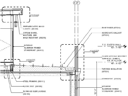
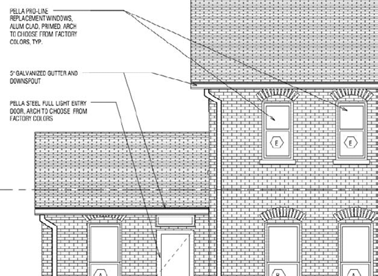
Notes are a critical part of communicating design and construction intent to owners and builders. No drawing set is complete without descriptions of materials and the work (Figure 19.1).
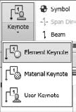
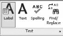
Revit has two ways for you to note your drawings. Both are located on the Annotate tab and highlighted in Figure 19.2. One of these methods is the Text command (shown on the left), and the other is the Keynote command (shown on the right).

The Text command in Revit consists of a field you can enter type into with or without a leader, bullets, or numbers. Text can be used for annotations, sheet notes (such as General Notes), legends, or generally anywhere you need to add a description or a note. Keynotes are predescribed text fields that are linked to elements and materials through a data file. Keynotes can be scheduled and standardized across the project but can't be directly edited within Revit. Both keynotes and text have specific uses across the project. Let's look at both.
Text is quick and easy to add to any view (including 3D views) and, like other drafting elements, is view specific. Text added to one view will not appear in any other location within the model, nor will the actual type that you insert into the text box hold any sort of parametric values.
You can access the Text tool from the Text panel on the Annotate tab (shown earlier in Figure 19.2).
To begin adding text, simply select the Text tool, choose a location to insert the text, and start typing. You'll be presented with the standard Revit crosshair, but it will have a small A in the lower corner
Your finished text box will look like Figure 19.3. You'll also notice that once you're finished with your initial text, you have a few tools available:
- Grips
The round grips on either side of the text box allow you to resize the box.
- Move
There is a move icon that appears in the upper-left corner of the text box. In addition, hovering your mouse anywhere within the highlighted text will also display a move cursor. You can click and drag from within the box or click the move icon on the upper-left corner to relocate it. When you're moving text with the move icon (or the Move command), the text and leader will relocate together. When moving text by dragging, the leader end will remain pinned while you relocate the text box. These methods allow you to move either the text or the text and the leader, depending on your need.
- Rotate
The upper-right corner will show a rotate icon. Clicking this icon will allow you to rotate the text box as you would any object within Revit. Remember that text within Revit will always position itself to be read from the bottom or right side of the screen, drawing, or view.
The Text family behaves like other Revit families, and text families maintain a parametric relationship throughout the project. Making changes to a text family in one location (changing font, font size, color, and so on) changes all the instances of that family throughout the model. To modify a text family, simply select a block of text or choose the Text tool. This will open the Type Selector, shown in Figure 19.4.

Here, the controls are rather limited and deal primarily with Instance parameters for an individual instance of text (alignment, location, and so on), which you can also set on the Ribbon. The Type Selector also allows you to change type or edit the text family. Click the Edit Type button, and it will open the text family's properties. Figure 19.5 shows the properties for Text 3/32" (75 mm) Arial.
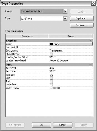
In this dialog box, you have more control over the style of the text. Here you can modify typical text properties, such as font style and size and width factor, and you can add formatting to the font, such as bold, italic, and underline.
At any time within the Text command or when the text box is selected, there are additional tools available on the Ribbon. The Format panel is divided into four sections that allow you to modify the instance of the text you've placed. Figure 19.6 shows the Format panel. Let's look at this panel in some more detail to better understand the toolset:

- Leaders
Note
The leftmost section of this panel allows you to designate the type and style of leader you want to add to your text box. By default, the upper-left A is selected (as in Figure 19.6), which designates that no leader is currently added. The other choices all will add a leader to the text. Reading from left to right, the options are no leader, a single segment leader, a double segment leader, and an arced leader. Leaders can be added at any time when you're placing or editing text and can also be removed at any time. Remember that when you're removing leaders, they will disappear in the order they were added.
- Leader Location
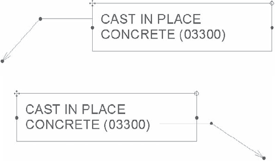
The second portion of this panel dictates leader location. Leaders can be added to the left or to the right and at the top, center, or bottom of the text box. Figure 19.6 shows the default with a left leader springing from the upper left of the text; leaders that spring from the right side typically come from the end of the text box (at the bottom). A double-segmented leader springing from the left and right will look like Figure 19.7.
- Format
The third portion of the text box controls the format of the text. These features—justification, bold, italicized, and underline—can also be modified using the Properties dialog box shown previously in Figure 19.4.
- Bullets
The rightmost portion of the Format panel allows you to add a bulleted or numbered list to the text box. By default, this style of formatting is not added, but by selecting the text box or the text within the box, you can add bullets, number, or letters to the text. Figure 19.8 shows the bulleting and numbering options.

Keynotes are written annotations that relate text to specific elements or materials in the model using an external file. You can control the formatting of the font style, size, and justification in the same manner you can format standard text, but keynotes and textnotes behave more like a typical Revit family. Using keynotes, you can insert different family types of text into the model, just as you would door or window families. These inserted families contain text that is not directly editable but instead is tied to an external TXT file. Inserting a keynote allows you to choose a value from the file and apply it to a material or element. Because keynotes and textnotes act as families in Revit, they can also be scheduled where standard text cannot. Although the Revit command is called Keynote, Revit can produce keynotes, textnotes, or a combination of both. Before we discuss how to add those note types, we'll cover the differences between a keynote and a textnote.
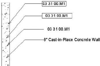
A keynote is a short numeric reference followed by a two-letter suffix. The keynote references a list or schedule located on the same sheet the note is placed that has a longer definition of the note. As an example, a keynote on a detail might read "033000.AA" with a leader pointing to an element in the drawing. The associated list on the side of the sheet would read "CAST IN PLACE CONCRETE." Figure 19.9 shows an example of a keynote legend.

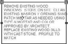
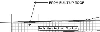
In contrast to keynotes, textnotes are the full, written description directly within the detail or view without the numeric reference key. Figure 19.10 shows an example of a textnote.
There is no wrong system to use, and Revit supports both ways of annotating sheets. Regardless of the method you use, the keynotes will adhere to the same process for use. Once an element is tagged with a keynote, it will retain that keynote in all other views in the model. If an element that has been tagged with a keynote in one view is then annotated in another view, it will automatically pull up the same keynote value. This can become a very powerful tool you can use to add consistency throughout the model for annotated elements.
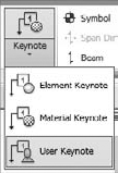
The Keynote command is located on the Annotate tab. When you select the Keynote tool, you have three note type options:
- Element
Use Element notes to keynote elements and assemblies within the model such as walls, doors, floors, or other family instances. This type of note is typically used if you want to annotate an entire assembly (such as a wall). Moving the Element keynote leader arrow off the wall will dynamically change the value of the note based on the element it points to. The keynote value can be preset for different family types within a template in the element's properties. We'll go into how to do that later in this chapter.
- Material
Using the Material note type will allow you to annotate specific materials within any elements. You can add notes for materials like concrete, gypsum board, rigid insulation, metal studs, and the like. Moving the Material keynote leader arrow off the wall will dynamically change the value of the note based on the material it points to. Material notes can also be predefined as part of your template. Material notes can be used in conjunction with Element notes.
- User
This option allows you to select any model-based component in Revit and define a custom keynote for it. Notes defined this way differ from those defined as Element or Material because they're not unique to the particular object selected. Once you move the keynote leader arrowhead, the note will not dynamically change. User-defined notes are static in that sense. They can be used in conjunction with Element and Material notes on any object but cannot be predefined.
You can use all of these note types in conjunction with one another. Using an Element note to add a keynote to a wall doesn't mean you cannot also use a Material note to call out the individual materials in the wall assembly.
A core concept of the Keynote tool is how the notes react with in the model. Keynoting an object in Revit lets you associate a text or numeric value with a family's keynote parameter. This value is consistent for every instance of that element within the model or project. For example, all walls have a type parameter called Keynote that lets you set the keynote value. If you keynote a wall, anywhere within the model, the keynote value in the type parameter will reflect that note. Consequently, any other wall of that type will be prepopulated with that keynote value. Changes to this keynote value will dynamically update the type parameter value and update any keynotes placed within the model tagged to this wall.
It's important to think of a keynote as a family type because keynotes will act more like a Revit family than they will like text. Keynotes behave similar to other Revit families in that you cannot edit the keynote directly within the model. All keynotes within the model are tied to an external TXT file. This TXT file is the only location where the value of the keynotes can be edited. This file can be modified at any point to add or remove notes and the edits can happen while the project is actively open. Figure 19.11 shows a sample portion of the file.
This external file is designed to keep the annotations consistent by storing them in one repository. Every time you add or change a note value and reload the TXT file back into the Revit model, all of the notes of that type dynamically update.
You can edit this TXT file or add one to the project at any time. You can have multiple keynote files for various projects, but you can have only one TXT file per project at a time. Revit does not allow for multiple keynote files to be linked to the model simultaneously.
Because the keynote file is a separate TXT file, remember that when transferring files to other offices or clients you'll need to include the TXT file as well as the RVT file if you are going to share information. If you don't send the TXT file, others will be able to see all of your notes but won't be able to change or edit any of them.
There are three Keynote text files in Revit that come with Revit by default. You can find all of them in C:Documents and SettingsAll UsersApplication DataAutodeskRAC 2011Imperial Library; they are called RevitKeynotesImperial.txt, RevitKeynotesImperial_2004.txt, and RevitKeynotesMetric.txt.
Edit any of these files in Notepad or Excel, and follow the format already established within the file. Let's look at this format of this file so you can understand how to customize the keynotes.
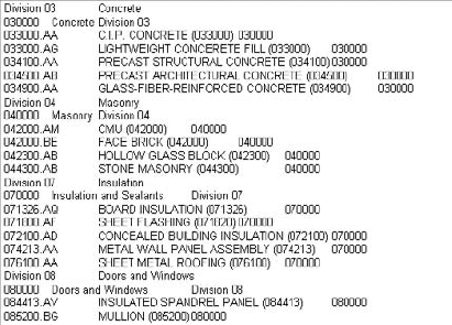
The first few rows of the file (Figure 19.12) designate the grouping of the notes. In this example, they consist of a label (Division 03) followed by a tab and then a description (Concrete).
Directly below this header is a secondary, or minor, grouping. This secondary grouping follows the same format as the primary group and provides better control over how the keynotes are displayed within Revit. This line follows the same format as the first: Label (033000), then a tab, then a description (Concrete), then another tab, then another description (Division 03). In this line, the description needs to match, identically, the label in the line above. This designates the second line as a subset to the first line. You can add as many or as few subgroups as you'd like. In our case, we have subcategories for each division, but that's not necessary.
Below the grouping are the contents of that group. These lines are articulated in the following format:
Label, Tab, Description (note body), Tab, Grouping
In the previous example in Figure 19.12, this reads as follows:
033000.AA [tab] C.I.P. CONCRETE (033000) [tab] 033000
where the [tab] is an actual tab, not the text.
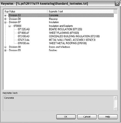
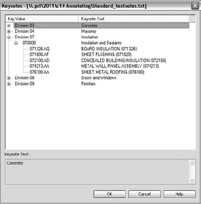
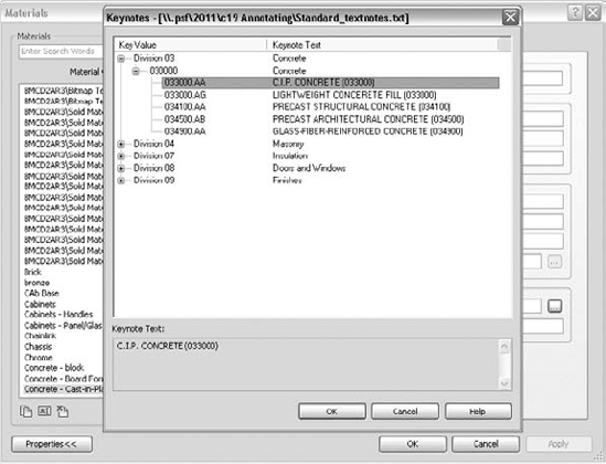
To get an idea of how this will all look once loaded into Revit, Figure 19.13 shows you the Keynote dialog box with Division 7 expanded.
Using the keynote file approach lets you add, remove, or edit notes and groups of notes. This might seem frustrating to have to open and load a separate TXT file every time you want to add or remove notes from the keynote list. However, remember that this also maintains consistency and a level of control over the master list that isn't available with simple text. Although it might be slow at stages to get all the project notes into the TXT file, it also means that your time to check and verify the notes is dramatically reduced.
Should managing keynotes directly in a TXT file not be a workflow you would like to maintain, there are some tools available online to help you accomplish this using a better graphic interface. Emc2 has a great tool (www.emc2architects.com/revit_tools.html) that will manage your keynote list, create headings and subheadings, and format the TXT file in a way that Revit can read. Tools like this are great for speeding up the editing process for keynotes and maintaining proper formatting of the TXT file.
Now that the Keynote TXT file is established and you've begun populating it with annotations, you need to link it to the Revit model. Loading this file into the Revit project is simple and needs to happen only once during the project. Additionally, loading this keynote file is a project setting, not a user one, so once the file is linked, all the users will have access to the keynotes.
To access the keynote settings and load the keynote text file, choose the Tag fly-out from the Text panel on the Annotate tab (Figure 19.14) and choose Keynoting Settings.

This command will open the Keynoting Settings dialog box (Figure 19.15). Here, you can define the project's keynote file as well as adjust some other settings. To load the keynote file, click the Browse button and navigate to the TXT file you've created.

The following are some of the other variables you can set in the Keynoting Settings dialog box:
- Path Type
Path Type defines how Revit looks for your text file using one of three methods:
- Absolute
The Absolute option follows the UNC naming conventions and navigates across your network or workstation for a specified location.
- Relative
This option locates the text file relative to the Revit project file. If you move the Revit file and the text file and maintain the same folder structure, Revit knows where to look for the keynote file.
- At Library Locations
This option lets you put the text file in the default library location defined in the File Locations tab of the Options dialog box (Application button

- Numbering Method
Numbering Method defines how the keynotes are numbered:
- By Keynote
This option allows you to number keynotes as they come from the associated text file.
- By Sheet
With this option enabled, Revit numbers the keynotes sequentially on a per-sheet basis.
To add keynotes to a Revit model, choose one of the three keynote types from the Annotate tab; then in your view, select the object you want to annotate and insert a keynote. Keynotes insert in an arrowhead, segment, note sequence. The arrowhead location will also define the element or material if you are using one of those note types. If the object doesn't have a note already defined, you'll be prompted to pick a note from the keynote list. Figure 19.16 shows a sample of this list.
Before inserting a keynote, we'll cover the three types of notes and explain how each might be used.
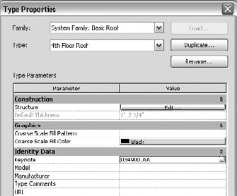
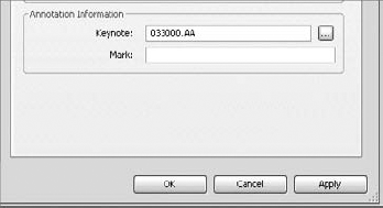
Element notes will annotate an assembly (walls, floors, roofs, and so on) or a component or family (doors, windows, furniture, and so on) within the model. Once keynoted, the assembly or component will capture the keynote value within the object's Type properties. In Figure 19.17 you can see the Keynote value is filled in for the Roof type, Basic Roof.
Alternatively, you can set this value through the object properties. By clicking the button next to the keynote value

When using an Element note to tag an assembly within Revit, simply click anywhere on the assembly. A tagged roof condition looks like Figure 19.19.
Material notes define the materials within a model. Whereas the Element notes can be used to define an assembly, Material notes can be used to define the materials within that assembly. For example, you can use an Element note to annotate a gypsum board wall assembly and a Material note to designate the layers of gypsum board and the metal stud in between.
To tag materials using the Material Keynote, select the Material Keynote button and hover your mouse over the materials comprising an assembly. As you hover over the various materials, you'll notice that predefined materials will show the note value and undefined materials will give you a question mark. Tagging the same roof assembly, you can specify all the materials that make up the roof element (Figure 19.20).

The Material Keynote tool is the second tool located on the Keynote fly-out on the Annotate tab (Figure 19.21). You'll notice that once you begin using any of the keynote tools, the last tool used will take the default icon location in the Text panel. In Figure 19.21, you'll see that this is currently set to the User keynote.

Like Element notes, Material notes can also be predefined. To predefine these note types, choose the Material button from the Manage tab (Figure 19.22).

Selecting the Materials button opens the Materials dialog box. To predefine a material's keynote, select it from the list on the left and choose the Identity tab (Figure 19.23).
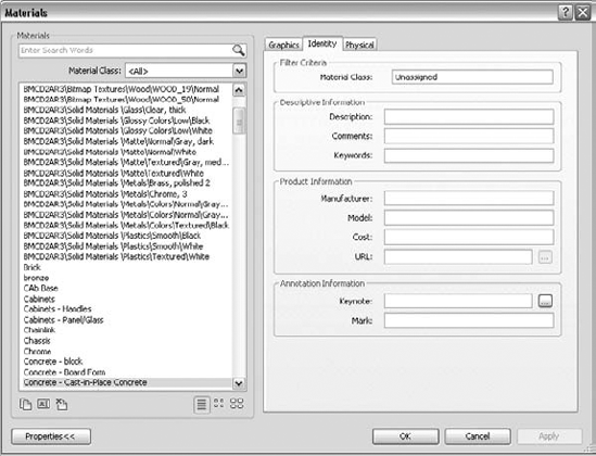
At the bottom of this tab is the Keynote field. Selecting in this field will allow you to click the same
Defining the note will enter a value into the Keynote field, as shown in Figure 19.25. As with Element notes, you can predefine a number of keynote values as part of your project template.
User Keynote is the third tool on the Keynote fly-out (Figure 19.26). User notes are different from Element and Material notes because they are view specific and cannot be predefined. Although they are still tied to the same TXT file and will update in the same manner as other notes, they are not tied to any geometry in Revit. User notes are meant to be used for all the instances when you don't have a modeled element or material but you still need to define a note. Some examples of things you wouldn't necessarily model would be sealant, backer rod, or flashing.
User keynotes are used primarily in drafting views. To use any keynote, a given view must have at least one model element or component visible within it. In the case of a drafting view, you will need to insert a 2D component (such as wood blocking or a steel stud) because keynotes cannot be used to note linework. Because User notes are not locked to specific model geometry, once they are inserted they can easily be copied or moved around within the view and pointed to any element. In this way, if you have sealant or flashing shown as linework, you can add a User note to the view, and then adjust the note leader and the note value to call out the sealant properly. You can change the value of a user keynote at any time simply by double-clicking the note value; this modification will not affect any other notes within the project.
Depending on your choice of keynote and your workflow, you might want to create a legend on each sheet for your notes. You might want only the keynotes that are on a given sheet to appear in the legend. Or you might want to have one legend for the entire project that will show all keynotes used in the project.
These lists usually reside on the side of the drawing near the title block information and can take one of two forms. The first type is all-inclusive and shows every note within the project. This style has the benefit of consistency between sheets in the set. The same note will always be in the same location in the list. The other type of keynote list includes only the notes that show up on a particular sheet. This has the advantage of supplying a list of notes customized for each sheet without extraneous information. Creating either list manually has traditionally been challenging. One of the benefits of Revit is the ability to automate either list, thus removing much of the chance for error in the process. Let's review how to create both types of lists.
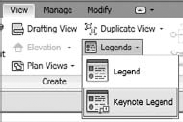
Creating a keynote legend in Revit is simple: choose the Legend button on the View tab and select Keynote Legend from the drop-down list (Figure 19.27). Once you click the Legend button, go ahead and name the keynote legend, and then click OK.
You'll be presented with what looks like a typical schedule dialog box called Keynote Legend Properties. There are only two fields available in a keynote legend, and by default, they are both loaded into the Scheduled Fields side of the Fields tab (Figure 19.28). Those fields are as follows:
- Key Value
This field contains the numeric value of the keynote.
- Keynote Text
This field contains the text value for the keynote.
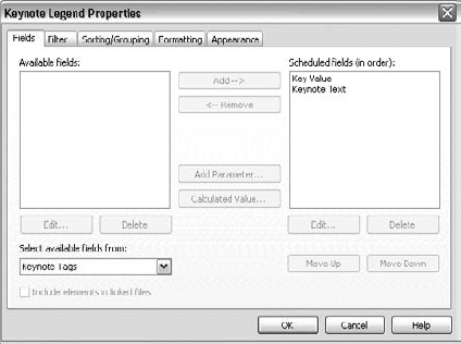
A keynote legend works like any other schedule as far as formatting and appearance goes. By default, the sorting and grouping are already established because the key value is used to sort. The one special item of note is located on the Filter tab. At the bottom of this tab is a feature unique to this type of schedule: a Filter By Sheet checkbox (Figure 19.29). Selecting this box gives you the ability to filter the list specifically for each sheet set; leaving the box deselected will supply a full list of the keynotes over the entire project.

Figure 19.29. The Filter By Sheet checkbox is located at the bottom of the Filter tab in the Keynote Legend Properties dialog box.
As with any legend, these can be placed on sheets again and again within the project. You're not limited to only one instance of the legend on a sheet as you are with other view types. Additionally, if you choose the Keynote legend that filters by sheet, it will dynamically modify the note list based on individual sheet contents. As views are added or removed from a sheet or notes are added to the project, the keynote legends updates accordingly.
Keynote legends are considered to be another type of legend view and will appear under the Legends node of the Project Browser.
Revit comes with a default Keynote family that allows you to produce both keynotes and textnotes using the default keynote TXT file. The family name is Keynote Tag.rfa. This family has four family types that let you change note styles within the project. You can see the four note styles in Figure 19.30.
The four default styles are
Keynote Number
Keynote Number — Boxed — Large
Keynote Number — Boxed — Small
Keynote Text
Each of these notes pulls information from the text file we discussed earlier in this chapter and reports it at the end of the leader.
Tags are text labels for elements such as doors, walls, windows, rooms, and several other objects that architects typically need to reference in a set of drawings. These tags typically refer to other schedules or information in other portions of the drawing set and are unique to the view they are inserted within. In Revit, tags are intelligent, bidirectional symbols that report information stored in an object's properties. You can enter a value directly into the family properties or right into the tag itself.
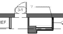
Once you've tagged an element and given the tag a value, the element will retain that value until you remove it. The value lives with the elements within Revit; it is not a property of the tag. This allows you to delete or remove tags without any fear of losing the data entered into the tag. It also means that once an element is tagged with information in one view, that same element will report that same information in any other view that it is tagged in without you having to have the information entered twice. To explain this a bit better, take the example of a door tag.
You've placed a door tag in a view. The tag initially had a "?" as a value, meaning that the door number was blank. You've entered a door number of 3-1. In another view, you can now tag the same door and have it automatically display a value of 3-1. You can also delete any, or even all, of the door tags for that door and have new tags you place also report the door number of 3-1.

In Revit 2011, you can also tag elements which are in linked models. While you cannot edit the properties of these elements (e.g. you cannot change the wall type or door number) you can add tags to any of the linked elements as you can if the same elements were part of your project file.
Tags are versatile elements in Revit. A tag can display a door number, but it can just as easily display any other properties of the door, such as fire rating, cost, or material type.
Tags can be automatically inserted when another element, such as a door or room, is placed within the model (by checking the Tag On Placement option in the Options Bar), or they can be inserted later in the project. The options to place a tag are all located on the Tag panel of the Annotate tab (Figure 19.31).
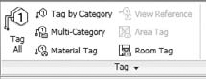
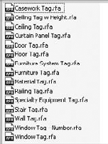
When you're adding tags, it's not necessary to find or choose the right tag—Revit will do that for you. Tag types are specific to the elements to which they are being tagged. For example, you can use a door tag to tag a door, but you can't use a door tag to tag a wall or other element within Revit. Figure 19.32 shows you some of the tags that are available; there is a tag for each type of object within Revit. You can customize each of the tag family types so you can graphically differentiate your door tags from wall tags, room tags, area tags, and so on.
When inserting the tag, you'll have several options regarding tag placement available in the Options Bar (Figure 19.33).
- Orientation
This first option allows you to orientate the tag horizontally or vertically. Tags, like text, will always read from either the bottom or right side of the sheet or view.
- The Tags Button
Clicking this button opens the Tags dialog box, where you can load various tags.
- Leader
The final three options deal with the tag leader. You can check the Leader check box on (or off) to have a leader show (or not show). While attached leaders are the default for Revit tags, the Attach End drop-down can be changed to not associate the end of the leader with the element you've selected. Using the Unattached End option allows the leader to float free of the object. The final option of this set for leaders is the default leader length. By default, the value is set to ½". When you're placing tags like wall tags that have leaders perpendicular to the wall they are tagging, it is a good idea to set a default length you are comfortable with. You can adjust the tag location after inserting them, but sometimes it's easier to set a good default value in leader length.
Note
On the Annotate tab, you'll find there are several methods you can use to insert tags into Revit. Each of these tools allows you to tag elements within a view in different ways. Each has different uses and can be used in conjunction or separately to help document your project.
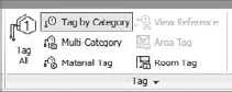
- Tag By Category
The Tag By Category button is possibly one of the most frequently used Tag commands. As we mentioned before, several tags are available in Revit, allowing you to tag a host of elements in the model. Click the Tag By Category button (shown in Figure 19.34) when you want to tag one element at a time, regardless of its category.
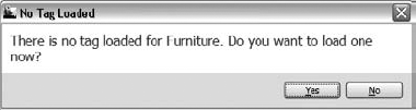
Using this tag command will allow you to select a door, a window, a wall—whatever single element you want to apply a tag to in the model. As you hover over elements, Revit will show the tag that corresponds to that element, allowing you to place it. Should the element you are trying to tag not have the associated tag loaded in the Revit file, Revit will prompt you to load it (Figure 19.35). You'll be presented with a dialog box asking you to load a tag, which you can do either from Revit's default stock or your own office library.
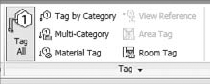
- Tag All
The Tag All command (Figure 19.36) will do exactly that'tag all the elements within a given view.
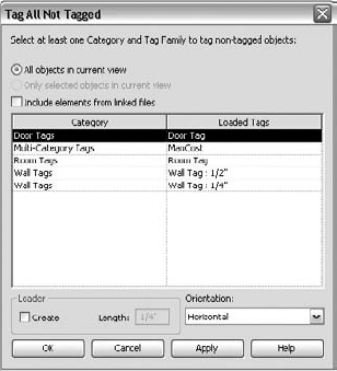
Tagging all the elements, however, doesn't mean that you have to tag everything within a view. That would be messy since everything within your view gets a tag. Revit will tag elements by the groups that you select. So, for example, you can tag all the doors. Or you can tag all doors, walls, and rooms—or any combination of any list of elements. When you select the Tag All command, Revit will present you with the Tag All Not Tagged dialog box (Figure 19.37). This dialog box displays a list of the elements in the view for which you have already loaded tags. Here, you can specify which elements can get tagged, what tag will be used, and if that tag will have a leader assigned to it. Use the Control key on the keyboard to select more than one element from the list. When you've selected the categories you would like tagged, click OK.
Tagging all the elements within a view can be a wondrous time saver—but only if you're OK with Revit choosing the location for each of the tags. In some cases, like rooms, Revit will place the tags in the middle of the rooms. For most spaces, that will work just fine. For other tag types, such as walls or doors, you might have to adjust tag locations to make sure everything reads properly.
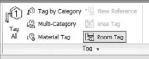
- Room Tag and Area Tag
These two tag types work in much the same way. They will tag the room elements or area elements, depending on the type of view you happen to be in. In the case of Figure 19.38, we are in a plan view that has no areas, so only the Room tag is active. To tag rooms or areas, simply select the tag type you want and select the room or area object. By default, when you place rooms or areas initially, Revit will automatically tag them for you.
- Material Tag
The Material Tag (Figure 19.39) is an interesting tag type that can best be described as a hybrid between text and a keynote.
This tag is actually a text box and leader, much like the Text command, and like Text, it will allow you to type a value into the text box. Like a keynote, the material that you tag will remember its note and the next time you tag an element, it will produce that same text. Change the text in one location and it will change it everywhere. To make this a bit clearer, let's use an example. From the book's companion website (
www.sybex.com/go/masteringrevit2011) download theJenkins.rvtfile for Chapter 19.Open one of the floor plans. In our example, we've chosen Level 3.
Choose the Material tag from the Annotate tab. Hovering over one of the existing, exterior walls, you'll see a question mark, as shown in Figure 19.40.
Place the tag and type EXISTING MASONRY WALL in the text box. Then click to insert a new tag.
As you hover over some of the interior walls, you'll notice that Revit will present you with the question mark, indicating materials that are not yet defined. Hover over the exterior wall, however, and you'll notice that the tag value automatically fills itself in (Figure 19.41).
Using these tag types can be a good alternative to using the Revit keynote system. This allows you some versatility over the note—you can type the text when adding the note—while also ensuring consistency across the project. This tag type only works with materials and can't be used on detail components or any linework.
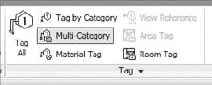
- Multi-Category Tag
The Multi-Category tag is a new tag type in Revit. This tag allows you to use the same tag style in a project to tag elements of different categories (Figure 19.42).


This tag type can be useful in a number of ways. Let's say you want to tag several elements in a floor plan and call out their manufacturer and unit cost. Historically, you would have to create a few different tags to tag Furniture, Systems Furniture, Casework, and any other category you had wanted to tag. Now, a single tag type can do this for you. Let's step through making a Multi-Category tag.
From the book's companion website (www.sybex.com/go/masteringrevit2011), download the Jenkins.rvt file for Chapter 19.
Open one of the floor plans. In our example, we've chosen Level 3.
Click the Application button and choose New
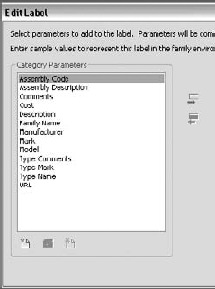
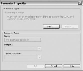
In the Family Editor, place a label. Once the label is located on the screen, the Edit Label dialog box opens. Here you'll see a long list of the family categories that are common across multiple family types—Assembly Code, Cost, Family Name, and Model, among others. The full list is shown in the Edit Label dialog box in Figure 19.43. To make our simple tag, select Manufacturer and Cost.
Finish the family and load it into the project.
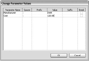
Now, select an element in the floor plan. In our example, we've chosen the dining room table. When the tag is placed, you will see the familiar question mark, indicating this element has no predefined value for either Manufacturer or Cost. Place the tag and double-click the question mark.
The Change Parameter Value dialog box (Figure 19.44) opens. Enter a value for both Manufacturer and Cost, and then click OK.
As you hover your mouse over other elements in this view, you'll notice the same behavior as with other tags. Elements that have predefined values will show the tag filled in while other elements without values will have question marks. Add a few more tags and you can begin to see some of the versatility of the Multi-Category tag.
Note
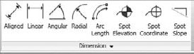
Dimensions are used to convey the distance or angle between elements or parts of elements. In Revit, a dimension is a bidirectional annotation that essentially tags distance or size. This means that you can edit the distance directly within the dimension string to move elements to a specific distance apart; likewise, the dimension updates automatically as the distance between elements changes. Dimensions are annotations, making them view-specific elements that appear only in the view where they're drawn. The Dimes ion tools are located on the Annotate tab.
Like all annotations in Revit, dimensions adjust to the scale of the drawing. They will always appear at the proper scale in the view. If you change the view scale, the dimensions automatically resize.
By default, a linear string of dimensions only dimensions parallel entities. Nonparallel elements by their very nature have a dynamic dimensional relationship. Dimensions in Revit always read from the bottom or from the right following the standard architectural sheet layout conventions. To place a dimension, choose any dimension tool and begin selecting entities in a sequence. You can keep selecting multiple entities in a given direction creating a dimension string across your drawing.

Note
Once the dimensions are placed, you can relocate them at any point either an individual dimension or for an entire string. Select the dimension and grab the blue square grip. By selecting and holding on this element you can move the witness line to a new host element without having to recreate the entire dimension string.
Every element in Revit has a list of parameters that has been assigned to it by default. Some of these parameters, such as Assembly Code and Mark, can be consistent throughout all the elements in Revit. Others, such as Length, Height, or Volume, are specific to element groups that could contain those kinds of parameters. The list of default parameters is available to describe most of what you need, but periodically you will want to add parameters to elements. These new elements, like the default ones, can be tagged and scheduled.
Depending on how you'd like to use a custom parameter, you can add them to your elements in Revit in a few ways:
If all you want to do is schedule the new parameter, you have a couple of options:
Add the parameter directly within the schedule itself. This will add a new parameter to your element family. Adding your parameter using this method adds it only to the element family in the schedule. For example, say you want to schedule the STC (Sound Transmission Class) of a wall. You could add this property directly within the wall schedule and the new parameter would only be available to objects in the Wall category.
Your second option if you only want to schedule parameters is to add the parameter directly into the project itself. Using this method, you can still schedule the new parameter, but you will have the option to add it to multiple categories. So, if you want to add a parameter for Unit Cost, you can add that to both your door and window categories at the same time.
If you want to be able to both schedule and tag your parameter, you will need to create what is called a shared parameter. This parameter is created as part of a separate file that is shared between the tag family and the element family you've created. An example use of this kind of tag might be for door hardware security. You can create a tag that will allow you to designate whether or not a door has a card reader to gain entrance to a room.
In the following sections, we will discuss how to create both of these parameter types as well as the pros and cons of each.
You can create custom project parameters at any time in the project cycle. Depending on how you create the parameters, you can assign them to one or more element categories within the model. You can also assign them to elements that have already been created or to element categories for elements that you have yet to create.
We'll step you through how to make a custom parameter that will be schedulable but not taggable. For this example, pretend you are working on an existing building and reworking a space. Much of what is on-site will need to be demolished, but you would like to reuse all the elements that are salvageable. As you are documenting the existing conditions, you will want to schedule the elements you'd like to keep. To do this, you'll make a parameter called Reuse.
To add a new project parameter, click the Project Parameters button on the Manage tab. This will display the Project Parameters dialog box (Figure 19.45). Click the Add button.
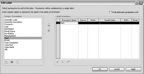
In the next dialog box, Parameter Properties, you will be asked to define a list of properties for the new parameter. Let's step through what these selections will be. Figure 19.46 shows a view of the completed dialog box.
Project Parameter or Shared Parameter is the first choice you'll need to make. We'll get to shared parameters later, so for now, leave it at the default of Project Parameter.
Name is used for describing the parameter. For this example, name the parameter Reuse.
The Discipline drop-down menu will give you three choices: Common, Structural, and Electrical. Leave the default selection, Common, for your parameter.
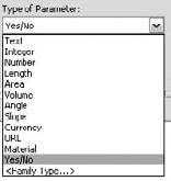
Type Of Parameter dictates what kind of parameter you have. As you can see from Figure 19.47, there are a variety of parameter types. It's important to understand some of these options and, more specifically, their differences. If you start creating formulas with your parameters, you'll quickly understand how imperative it is to use the proper type. For instance, you cannot multiply Angle x Volume. Text cannot be added to a formula. Integers do not have decimal values. Many of these values are easy to understand if you apply a bit of logic. For our example, use the Yes/No type.
Type Or Instance Parameter controls the uniqueness of the parameter itself. Probably the best way to explain the difference between these two options is to describe a couple of use cases:
Type parameters are used for parameters that will be consistent across a type. This type is defined as a subset of a family. Let's take a door family, for instance. In the door family, you will want to define types that are 36" (926 mm), 34" (876 mm), 32" (826 mm), and 30" (726 mm) doors. To do so, you'd use a type parameter. When you insert the door, you can choose between these predefined types in the Type Selector drop-down.
Instance parameters are used in cases where you might have too much variety or uniqueness of an element property to want to define a series of types. A good use for an instance parameter is to specify the length of a countertop. When you insert the countertop into your model, you'll be able to drag the length of the counter to fit your needs rather than have to choose a predefined length from the Type Selector.
Both parameter types can be mixed within a given family. In this example, use an instance parameter because you want to designate on an element-by-element basis whether something is reusable.
Group Parameter Under is an organization tool. When you open your Element Properties, depending on how many parameters you add, you can acquire a long list. This tool allows you to group new parameters into any given category.
Category is where you define all the category types that our Reuse parameter will be associated with. There are 58 categories in Revit to which you can assign this parameter. For our example, choose Doors, Windows, and Furniture. Categories are flexible. If you decide you need to change categories after you create your parameter, you can easily come back and modify your selection.
Once you're finished, click OK. This will take you back to the original dialog box where you can choose to add another parameter or, in our case, just click OK to exit the Parameter Properties dialog box completely.


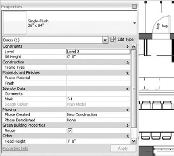
Back in the model, you can now select a door (because it is one of the categories you chose) and see that you have added a Reuse parameter to it in the form of a checkbox (Figure 19.48).
Now that you've created a custom parameter in the project, it's even easier to create one while in a schedule. You can create a custom parameter while creating a schedule or after the fact by simply modifying one. To create a parameter, simply click the Add Parameter button in the Schedule Properties dialog box (Figure 19.49). This will open the same dialog box as clicking the Project Parameter button, with the exception that the Categories selections will be grayed out because you can only create parameters in schedules for the element being scheduled.

When you want to schedule and tag a custom parameter, you will need to use shared parameters. In the earlier example, you learned that shared parameters are useful for creating a tag for the STC rating on a wall, scheduling which doors have security systems as part of the door hardware set, or specifying which equipment in a lab will require special gases (oxygen, argon, others). None of these parameters exist by default in any of the Revit families, but they are all values that you might want to tag or schedule, depending on the type of project you are working on.
These same parameters do not exist in any of the tags as well, so in order to tag these parameters, you need to create the parameter type in both the tag and in the element family.
Don't worry—it's not as complicated as it all sounds, but you will need to follow some steps fairly closely. Once you have added a shared parameter to your project, you cannot modify it. If you want to change it, you'll need to delete it and re-add the parameter. So, it behooves you to make your choices thoughtfully.
Let's look at the workflow behind creating a shared parameter. You'll do this with an example of creating a custom wall parameter called STC so you can tag the sound transmission class of the wall types. To get started, navigate to the book's companion website (www.sybex.com/go/masteringrevit2011) and download the Jenkins.rvt file in the Chapter 19 folder.
The first thing we need to do is create a new, shared parameter file. This file will be what talks and translates the values of the shared parameter between the tag, family, and project.
To create a shared parameter, click the Shared Parameter button on the Manage tab. This will open the Edit Shared Parameters dialog box (Figure 19.50).
Now, click the Create button to open the Save As dialog box. Name your shared parameter file. For our example, we've named it STC; however, if you plan to make more than one shared parameter, you might want to name it something more universal. All of the shared parameters for a given project will ultimately live in the same file. Choose File
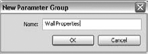
Now you need to give the shared parameter a group. This group is a hierarchical collection. So, for the wall's STC, you will want to create a group called Wall Properties (Figure 19.51). This grouping allows you to easily sort different parameters within project categories. Name the group, and click OK.
Once you have a group, you'll see the Parameter buttons are now active. Click the New button, and let's create a shared parameter. Name the parameter STC. Leave the Discipline setting at Common. For Type Of Parameter, choose Integer. Since STC ratings are whole numbers, you can use the Integer type and eliminate any decimal places you'd have if you used Number as the type (Figure 19.52). Once you've entered the settings, click OK.
You should see the new STC parameter in the Edit Shared Parameters dialog box. Click OK to exit this dialog box.


You've now created a shared parameter. The next step is to assign it to a category.
The shared parameter is now defined, but we don't have it associated with any categories yet.
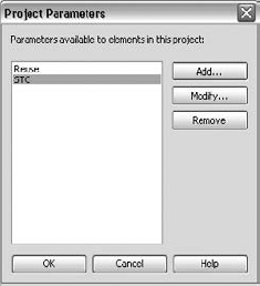
Click the Project Parameters button on the Manage tab to open the Project Parameters dialog box. You'll see the Reuse parameter you created earlier (Figure 19.53). You want to add a new parameter, so click Add.
The Project Parameters dialog box opens. This time, select the Shared Parameter radio button, and then click Select. In the resulting dialog box, browse to the STC file you just created. Select the file and click OK. You'll see that many of the fields are now grayed out. This is because you have already preselected this information. For a category type, select Walls (Figure 19.54).
Click OK to exit the dialog box. You'll see the new shared parameter (STC) next to your previous project parameter (Reuse) in the Project Parameters dialog box (Figure 19.55).
Now that the STC parameter is part of the project, you can begin assigning values to it. Open Level 3 and select one of the walls. By scrolling down in the Properties Palette, you'll notice that the STC parameter is now at the bottom (Figure 19.56). Enter a value of 45 and click Apply or mouse out of the pallet.


So far, you've created a shared parameter and added it to the Walls category, and you're able to add values to it. These are all features you could have leveraged with a project parameter. The benefit of using a shared parameter is being able to tag it. The final step in this process is creating a tag and tagging the STC parameter in the wall.
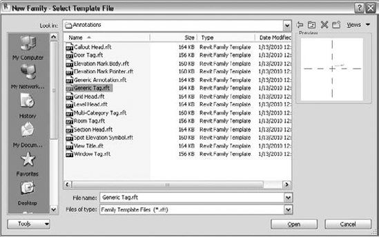
The first thing you'll need is a new tag. Since you're tagging a wall, there isn't a default wall tag type, so you'll need to make a generic tag and apply it to a wall condition. Click the Application button and select New
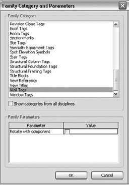
Next, you'll assign the correct category to the tag. By default, a generic tag is just that: generic. You want it to report information from the Doors category, so at the top of the Home tab, click the Family Category And Parameters button (it has a small file folder in the lower-right corner), shown in Figure 19.58.
With the Family Category And Parameters dialog box open, choose Wall Tags from the bottom of the list (Figure 19.59), and click OK.
With the proper category selected, you need to add a label for your tag. Click the Label button on the Text panel of the Home tab (Figure 19.60).
For our first label, you want to add a mark (Figure 19.61). This will call out the wall type from the Wall schedule in your documents and help you associate the proper wall with the STC rating. Select the Mark parameter and place it above the green grid in the family.
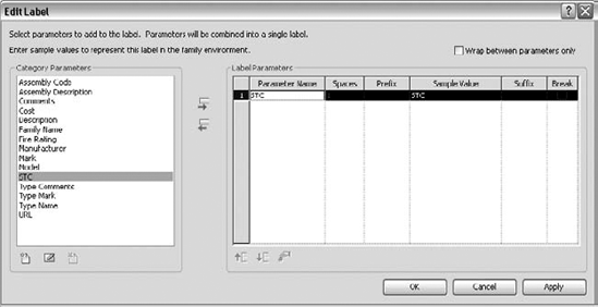
With the Mark parameter placed, let's add the STC parameter. Choose the Label tool again, and this time, click the Add Parameter button at the bottom of the Category Parameter column

You'll now see the STC parameter in the list. Select it and drag it to the right side of the dialog box (Figure 19.63). Click OK to close the dialog box and place this label under the green dashed line and under the mark.
With all the labels added, you can brush up the tag with a bit of linework to help differentiate the tag from the rest of the drawing. For our example, we've created a simple, divided box, shown in Figure 19.64. Once this is done, you're ready to load it into the project by clicking the Load Into Project button.
Back in the project, you're ready to tag the wall. Choose Tag By Category from the Annotate tab, and select the wall you have already given a value of 45 to for the STC. You'll see the wall type and STC rating populate within the tag (Figure 19.65).


And that's it. Once you've stepped through this workflow a few times, it will quickly become old hat, and you'll be able to add custom parameters to projects and tag them without a second thought. One thing to keep in mind, however, while you're doing all of this is that once you have added a shared parameter to your project, you will not be able to change any of the properties of the parameter itself. If you set the parameter to Integer and really wanted Number, you'll need to go back, delete the parameter, and start over. Also remember when working with a team, shared parameters work much like keynotes with their external TXT files. If you are sharing the project file with the idea that it will be edited by another team, be sure to include the shared parameter file.
- Annotate with text and keynotes.
Although a picture is worth a thousand words, you will still need notes in order to make drawings understandable and be able to call out key elements in each view. Understand how to create and modify text and keynotes for a complete set of documents.
- Master It
To properly utilize the keynoting feature, you'll need to understand what each of the three keynote types do and how they're used. List each and explain how they can be used in a project.
- Use tags.
Tags are text labels for elements such as doors, walls, windows, rooms, and several other objects that architects typically need to reference in a set of drawings. These tags typically refer back to other schedules or information in other portions of the drawing set and are unique to the view in which they are inserted .
- Master It
Inserting tags quickly can be a good way to make documentation time more efficient. How can you quickly tag a number of elements in the model at the same time?
- Adding Dimensions
Dimensioning is a critical part of the project documentation allowing you to communicate the distance elements are from one another.
- Master It
Adding dimensions is a necessary part in any project. However, in a project workflow, you will typically want to change the location of a dimension's witness line without having to recreate the entire dimension. How do you move a witness line without remaking the entire dimension?
- Set project and shared parameters.
Revit lets users add as many custom parameters to an element as are needed to document the project. These parameters can be both tagged and scheduled, depending on how they are made.
- Master It
You need to add a custom parameter for your project to track the percentage of recycled content in materials. What's the best way to go about doing this?