3.2. THE LINES IN THE SAND 41
Additional three-dimensional models can be run to examine the effects of the length of the
beam. Such analyses verify the dependence of both the tip deflection and normal wall stress on
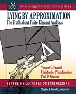
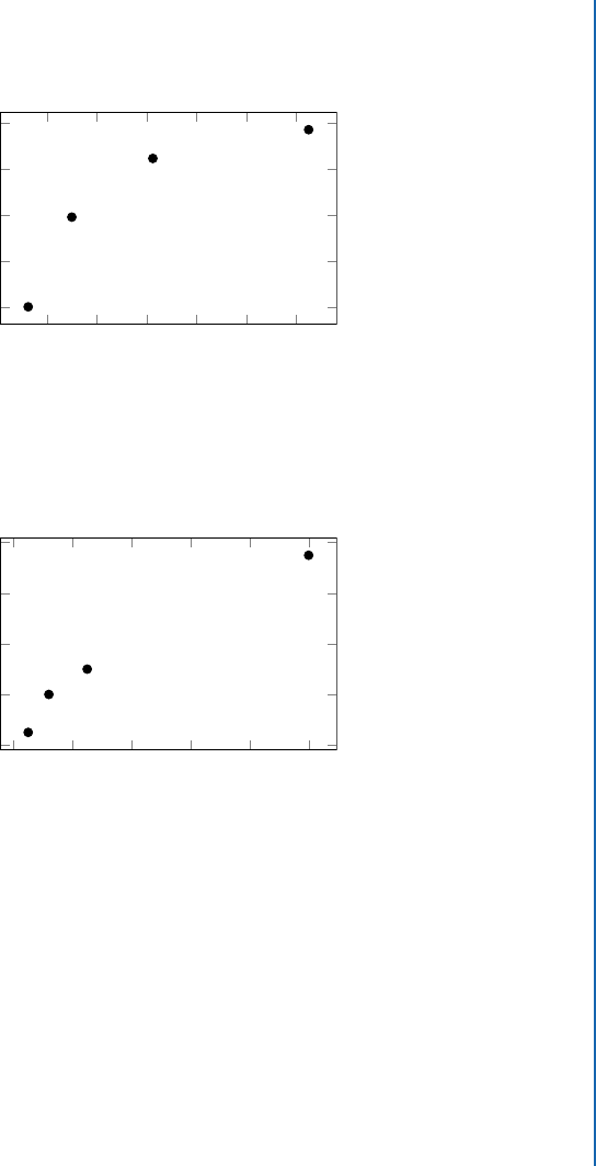
the beam’s span-to-depth ratio, as evidenced by results in Figs. 3.9 and 3.10.
2 4 6 8 10 12
80
60
40
20
0
4QBOUPEFQUI SBUJP
1FSDFOU &SSPS
Figure 3.9: e tip deflections in short beams predicted by Euler-Bernoulli beam theory become
progressively inaccurate for relatively short beams.
0 5 10 15 20 25
80
60
40
20
0
4QBOUPEFQUI SBUJP
1FSDFOU &SSPS
Figure 3.10: e normal stress at the fixed end predicted using Euler-Bernoulli beam theory in short
cantilever beams can underestimate the actual normal stress substantially.
3.2.3 A THICK-WALLED PRESSURE VESSEL
e simple formulae outlined in Chapter 2 represent nearly all states of uniform or linearly vary-
ing stress. Radial and hoop stresses in pressure vessels become uniform through the thickness
as the radius-to-thickness ratio becomes large. Because these formulae are simple and because
the variation of both radial and hoop stress becomes nonlinear for thick vessels, analysts may be
tempted to push the limits of the simple formulae. Here we point out that, as with the other
simple formulae, the deviation from the uniform stress state occurs gradually. When the radius-

42 3. WHERE WE BEGIN TO GO WRONG
to-thickness ratio falls below 10, errors arising from predicting stresses with thin-walled formulae
become appreciable and thick-walled formulae become increasingly necessary.
SimCafe Tutorial 4: Hoop Stress in a ick-Walled Pressure Vessel
e purpose of this tutorial is to illustrate how thin-wall pressure vessel theory grad-
ually loses applicability as the radius-to-thickness ratio decreases. As before, this happens
gradually as the vessel walls become thicker. is tutorial is meant to highlight where it is
relatively straightforward to apply three-dimensional or axisymmetric FEA and resolve a
solution correctly for thick-walled vessels.
Follow the directions at https://confluence.cornell.edu/display/
SIMULATION/Pressure+Vessel to complete the tutorial.
Example 3.3: A Hydraulic Test Stand
Consider a hydraulic pressure vessel used to apply loads to experimental fixtures in an
undergraduate statics and strength of materials laboratory, as shown in Fig. 3.11.
BYJBM
BYJBM
b
a
p
Figure 3.11: Hydraulic test stands are typically moderately thick-walled pressure vessels.
Consider that the pressure vessel is verging on the limits of the thin-wall theory. e
outer diameter is 4 in with an inner diameter of 3 in and a 0.5 in wall thickness, giving an
I

3.2. THE LINES IN THE SAND 43
Example 3.3: A Hydraulic Test Stand (continued)
average radius-to-thickness ratio of 3.5. Exploiting symmetry, an axisymmetric analysis of
half the vessel is created. e vessel is internally loaded with a constant pressure of 1000 psi.
e axisymmetric deformed mesh and internal stresses indicate a stress riser in the bottom
of the tank where membrane and bending stresses coincide, as shown in Fig. 3.12.
Figure 3.12: Pressure vessel hoop stress maximum occurs in the bottom of a thick-walled vessel.
Far from the discontinuity of the vessel corner, the hoop and radial stress variations in the
axial direction in the cylinder wall vanish, as shown in Fig. 3.13.
Figure 3.13: Pressure vessel hoop stresses are no longer uniform through the wall of a thick-
walled vessel.
I

44 3. WHERE WE BEGIN TO GO WRONG
Example 3.3: A Hydraulic Test Stand (continued)
Paths through the domain may be defined in many commercial finite element software
packages. Here, the variation of hoop stress through the wall thickness is not negligible. e
results shown in Fig. 3.14 show the maximum value on the inner diameter predicted correctly
by thick-wall theory.
Figure 3.14: Radial variation of hoop stress in the uniform section of the cylinder wall shows a
peak value at the inner wall that is underestimated by thin-wall theory.
When we vary the vessel thickness, the gradual degradation of the predictions using thin-
walled formulae become evident, as shown in Fig. 3.15.
0 10 20 30 40
40
20
0
"WFSBHF SBEJVTUPUIJDLOFTT SBUJP
1FSDFOU &SSPS
Figure 3.15: Hoop stresses in thick-walled pressure vessels are underestimated by relations based on
thin-walled pressure vessel theory.
..................Content has been hidden....................
You can't read the all page of ebook, please click here login for view all page.