34 3. WHERE WE BEGIN TO GO WRONG
3.2.1 A STEPPED AXIAL ROD
SimCafe Tutorial 2: Stress Concentration in a Stepped Axial Shaft
When geometries exhibit discontinuities along a loading path, stress concentrations
generally arise. Stress flow is analogous to fluid flow and steep gradients that result in navi-
gating sharp discontinuities result in enhanced stress intensity. What may not be evident is
that a discontinuity in geometry requires modeling the geometry in multiple dimensions in
order to capture how the stress flows through the domain. us, one-dimensional simplifi-
cations are not capable of capturing these important effects.
e purpose of this tutorial is to showcase perhaps the simplest stress concentration
and point out that it can be resolved in two- or three-dimensions. Simple one-dimensional el-
ements (i. e., simple axial bar elements) that capture constant stress within an element are in-
sufficient to capture stress concentrations, even when many elements are used. In other words,
the requisite theory is absent, so mesh refinement is of no utility in converging on the solu-
tion. When the element formulation does not contain the necessary physics, h-convergence,
or using more elements, captures no more of the solution than does a coarser discretization.
is tutorial is meant to highlight where it is relatively straightforward to apply FEA and
resolve a solution correctly that belies analytical treatment with uniaxial formulae (such as
axial
D P =A).
Follow the directions at https://confluence.cornell.edu/display/
SIMULATION/Stepped+Shaft to complete the tutorial.
Example 3.1: A Stepped Axial Rod
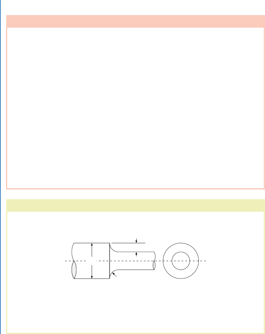
Consider a stepped shaft under uniform axial load, P , as shown in Fig. 3.1.
D
r
h
Figure 3.1: Geometrical description of a shaft with a discontinuous step.
Stress concentrations arise due to coupling of the stress response in multiple direc-
tions. In the axisymmetric geometry pictured in Fig. 3.1, simplified two-dimensional theory
of elasticity can be employed to derive approximate theoretical expressions for the observed
I

3.2. THE LINES IN THE SAND 35
Example 3.1: A Stepped Axial Rod (continued)
stress risers, by fitting such models to experimental data [Solverson, 1953]. Many stress con-
centration factors fit in this manner are collected in Young and Budynas [2002]. For a stepped
shaft with circular fillets:
h D 3 in
r D 1 in
D D 8 in
h=r D 3
2h=D D 3=4 D 0:75;
a simple fit formula for the axial stress concentration is accurate to within 5% and given by:
K D C
1
C C
2
2h
D
C C
3
2h
D
2
C C
4
2h
D
3
C
1
D 1:225 C 0:831
p
h=r 0:010.h=r/ D 2:634
C
2
D 1:831 0:318
p
h=r 0:049.h=r/ D 2:529
C
3
D 2:236 0:5220
p
h=r C 0:176.h=r/ D 1:8599
C
4
D 0:63 C 0:009
p
h=r 0:117.h=r/ D 0:9654
) K D 1:377;
and
max
D K
nom
D K
P
A
min
D K
4P
.D 2h/
2
D 1376 psi:
e response of a circular stepped shaft in tension is axisymmetric. An axisymmet-
ric analysis undertaken in ANSYS predicts the stress concentration to within the order of
accuracy of the simple formula fit, as shown in Figs. 3.2 and 3.3.
I

36 3. WHERE WE BEGIN TO GO WRONG
Example 3.1: A Stepped Axial Rod (continued)
Figure 3.2: e finite element method predicts the axial stress concentration in a stepped shaft.
Figure 3.3: e local axial stress concentration is shown in the vicinity of the step fillet.
Because these effects arise from coupling of stress in different directions, one-dimensional theories
are incapable of modeling stress concentrations in the vicinity of geometric discontinuities such as
re-entrant corners or fillets. Users must be careful to remember that in such cases two- or three-
..................Content has been hidden....................
You can't read the all page of ebook, please click here login for view all page.