
28 2. LET’S GET STARTED
w
B
w
3
2w
3
w
w
C
w
3
2w
3
w
w
D
w
3
2w
3
w
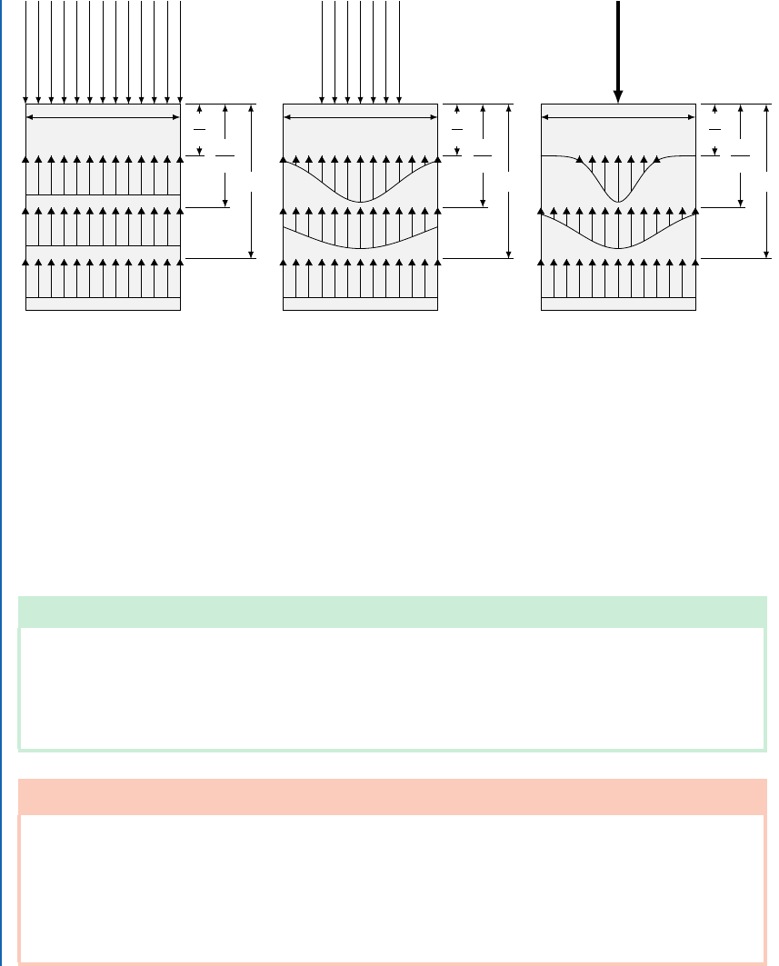
Figure 2.14: Statically-equivalent sets of applied loads distributed differently over a boundary or part
thereof do not alter the internal stresses and their distribution several characteristic dimensions (here,
measured in terms of the width, w) away from the applied loads. Here, a compression specimen is
subjected to equivalent loads (P ) over different portions of its ends: (a) full end, (b) half end, and (c)
point load. Approximately one specimen width into the bar, the state of stress is a uniform constant
stress corresponding to P =A.
2.6 COMBINED LOADING
Note To e Instructor
While students may recognize these idealized loading cases and their respective simple formulae,
we often observe that how to linearly superpose these stress components under conditions of even simple
combined loading still eludes students even after exposure to the finite element method. Here we consider a
simple illustration for which finite element analysis is both straightforward and useful in framing students’
hand calculations as benchmarks for simulation results.
SimCafe Tutorial 1: Combined Loading in an Idealized Signpost
e purpose of this case study is to illustrate how combined loading is handled in a
straightforward manner using the finite element method. It presents a case study wherein
students can perform parametric studies varying the degrees to which the combined load-
ings are dominated by either axial, bending, torsional, or transverse shear response. It also
showcases how internal stresses from combined loads are superposed in a linear analysis.
I

2.6. COMBINED LOADING 29
SimCafe Tutorial 1: Combined Loading in an Idealized Signpost (continued)
Follow the directions at https://confluence.cornell.edu/display/
SIMULATION/Signpost to complete the tutorial.
Example 2.2: Combined Loading in an Idealized Signpost
e cantilevered signpost shown in Fig. 2.15 has dimensions x
1
D 6 ft, z
1
D 4 ft, b
2
D
13 ft, h
1
D 28 ft, and h
2
D 8 ft. e system is subjected to the external loads w
z
D 900 lbf=ft,
w
0
D 700 lbf=ft, F
y
D 8000 lbf, and F
z
D net weight of the signpost. e signpost is made of
steel, and it is assumed that the signpost will remain in its elastic range. is means that when
the external load is removed, the material will return to its original shape without suffering
permanent deformation.
4JHOQPTU $SPTT 4FDUJPO
d
i
d
o
x
y
z
'JYFE 4VQQPSU
4UFFM 1PTU
F
z1
h
1
h
2
b
2
z
1
x
1
F
y1
w
z
w
x
=
z
h
1
+h
2
w
0
Figure 2.15: Geometrical description of the signpost illustrating dimensions and loads.
e post diameters d
o
and d
i
must be designed so that the total combined normal stresses and
combined shear stresses do not exceed allowable values. Assume allowable stresses of 25 ksi
and 16 ksi for normal and shear stress, respectively, which already account for an appropriate
factor of safety. is example is adapted from Papadopoulos et al. [2013] with permission
and with credit due to Genock Portela.
..................Content has been hidden....................
You can't read the all page of ebook, please click here login for view all page.