


Using z/Pro as a Cloud infrastructure for Oracle
|
Attention: The following command conventions are used in this chapter:
•z/VM commands are prefixed with ==>
•Linux commands that are running as root are prefixed with #
|
This chapter describes implementing a zCloud architecture for a development logical partition (LPAR) that supports Oracle on Linux on System z.
By using Cloud architecture, application developers can create their servers as needed with the expiration of servers that are set to a defined date.
This chapter includes the following topics:
12.1 zPRO introduction
The administration and use of a z/VM system can be a highly technical and specialized process. The administrator requires certain skills, most notably of which is knowing how to navigate a 3270 terminal interface. Users that are new to the platform or unfamiliar with the intricacies of z/VM might see that as a deterrent to getting started.
zPro from Velocity Software makes the administration of z/VM significantly easier by providing a web-based front end to most of the tasks that are done regularly. zPro enables cloud computing through which a user can create any number of virtual machines to fit their business requirements. If an external security manager (ESM) is available, such as, the Resource Access Control Facility (RACF) Security Server for z/VM, the web-based interface also extends to it.
Users of zPro can be restricted to perform only certain tasks that are relevant to their responsibilities. Functions, such as, creating virtual machines, allocating disk space, changing memory sizes, administering the Shared File System (SFS), or even RACF can be tailored to the needs of the specific user.
12.2 Cloud implementation overview
This section provides an overview of a Cloud implementation.
12.2.1 Requirements
Managing a large z/VM system is a specialized skill. It involves understanding the concepts and facilities that z/VM provides and how to configure and use them to construct the environment that is needed for your organization. The z/VM Systems Management Application Programming Interface (SMAPI) simplifies the management of z/VM with a standardized, platform-independent programming interface that can reduce the required skills in this environment.
SMAPI must be configured so that it can be used. Because the intent is to use zPro with the SMAPI, these configuration changes include those that are required for zPro.
The following overall steps are required:
1. Directory Maintenance (Dirmaint) changes
2. SMAPI configuration
The zPRO software also is needed for Cloud implementation.
12.2.2 Dirmaint configuration
Because SMAPI works with Dirmaint, changes are needed to the Dirmaint configuration.
Complete the following steps to make the necessary changes:
1. Log on to Dirmaint.
2. Press Enter twice to stop the application.
The AUTHFOR CONTROL file is used to tell Dirmaint, which users (or virtual machines) are authorized to issue commands.
3. Edit the file by using the following command:
==> xedit authfor control e
The entries that are shown in Figure 12-1 must be added to the file for the SMAPI and zPro servers.
|
ALL VSMGUARD * 140A ADGHOPSM
ALL VSMGUARD * 150A ADGHOPSM
ALL VSMWORK1 * 140A ADGHOPSM
ALL VSMWORK1 * 150A ADGHOPSM
ALL VSMWORK2 * 140A ADGHOPSM
ALL VSMWORK2 * 150A ADGHOPSM
ALL VSMWORK3 * 140A ADGHOPSM
ALL VSMWORK3 * 150A ADGHOPSM
ALL ZPRO01 * 140A ADGHOPSM
ALL ZPRO01 * 150A ADGHOPSM
ALL ZPRO02 * 140A ADGHOPSM
ALL ZPRO02 * 150A ADGHOPSM
ALL ZPRO03 * 140A ADGHOPSM
ALL ZPRO03 * 150A ADGHOPSM
|
Figure 12-1 AUTHFOR CONTROL file
4. Create a file that is called CONFIGSM DATADVH D (as shown on Figure 12-2) by using the following command:
==> xedit configsm datadvh d
|
/* SMAPI config */
ALLOW_ASUSER_NOPASS_FROM= VSMGUARD *
ALLOW_ASUSER_NOPASS_FROM= VSMWORK1 *
ALLOW_ASUSER_NOPASS_FROM= VSMWORK2 *
ALLOW_ASUSER_NOPASS_FROM= VSMWORK3
ALLOW_ASUSER_NOPASS_FROM= ZPRO01 *
ALLOW_ASUSER_NOPASS_FROM= ZPRO02 *
ALLOW_ASUSER_NOPASS_FROM= ZPRO03 *
ASYNCHRONOUS_UPDATE_NOTIFICATION_EXIT.TCP= DVHXNE EXEC
ASYNCHRONOUS_UPDATE_NOTIFICATION_EXIT.UDP= DVHXNE EXEC
|
Figure 12-2 CONFIGSM DATADVH file
The entries ALLOW_ASUSER_NOPASS_FROM permits the SMAPI server machines and zPRO server machines to issue Dirmaint calls as another user.
The entries ASYNCHRONOUS_UPDATE_NOTIFICATION_EXIT notifies the SMAPI of changes that are made to the directory.
5. Restart Dirmaint by using the following command:
==> dvhbegin
12.2.3 Dirmaint direct access storage device configuration
zPro relies on Dirmaint’s view of the disk subsystem to allocate minidisks. Make sure that the disk volumes that are needed for minidisks are available to Dirmaint and, optionally, that they are placed into groups (disk pools) for more generic placement of minidisks.
Defining disk volumes to Dirmaint and placing those volumes into groups is done in the EXTENT CONTROL file. This file is under the control of Dirmaint. To see the contents of the file, run the following command:
==> dirm send extent control
The EXTENT CONTROL file is transferred from Dirmaint to the reader queue of the virtual machine from where the command is issued.
Modify the REGIONS section by adding disk volumes for minidisk allocation. The start and end fields indicate the part of the volume that is to be used for allocation and are typically START and END so that the entire volume is used. Pay special attention to the device type because it should be the exact device type of the volume to make best use of the space and prevent allocation errors.
The GROUPS section also must be changed by adding regions (volumes) to existing groups, or creating groups from other volumes in the REGIONS section.
When modifications are complete, send the file back to Dirmaint by the following command:
==> dirm file extent control
Then, tell Dirmaint that the file was updated by using the following command:
==> dirm rldextn
The new REGIONS and GROUPS definitions are available for use by Dirmaint and zPro.
12.2.4 SMAPI implementation
If your system is not in an ensemble, the following changes for SMAPI must be made on MAINT to turn off ensembles for SMAPI:
•Access the 193 disk, as shown in the following example:
==> acc 193 f
Ready; T=0.01/0.01 15:20:22
•Access the SMAPI worker server data directory in read/write mode, as shown in the following example:
==> acc vmsys:vsmwork1.data g (forcerw
Ready; T=0.01/0.01 15:20:35
•Copy DMSSISVR NAMES from the 193 disk to the directory, as shown in the following example:
==> copy dmssisvr names f = = g
Ready; T=0.01/0.01 15:20:50
•Xedit the file on the directory, as shown in the following example:
==> x dmssisvr names g
Ready; T=0.01/0.01 15:25:15
•Comment out the section of the file at the end under the comment, as shown in Figure 12-3.
|
**************************************************************
*** the following machines are only available in ensembles ***
**************************************************************
* Default Management Network Server
*:server.VSMREQIM
*:type.REQUEST
*:protocol.AF_MGMT
*:address.INADDR_ANY
*:port.44446
* Primary Vswitch Controller
*:server.DTCENS1
*:type.VCTRL
* Backup Vswitch Controller
*:server.DTCENS2
*:type.VCTRL
* Management Guest
*:server.ZVMLXAPP
*:type.MG
|
Figure 12-3 DMSSIVR NAMES
When the configuration steps are completed, start the SMAPI server machines by using the following command from an authorized user:
==> XAUTOLOG VSMGUARD
This virtual machine automatically starts the other SMAPI server machines. To verify that the SMAPI is running and listening to requests, run the following commands:
==> vmlink tcpmaint 592
==> netstat
As shown in Figure 12-4, the results show a listener at port 44444 and 55555, which are SMAPI TCP/IP services.

Figure 12-4 NETSTAT output that validates SMAPI
12.2.5 zPRO implementation
The installation of the zPro product is done by using the Velocity Software product management virtual machine ZVPS. For more information about the zPRO installation process, see the Velocity Software Installation Guide.
After the installation is complete, zPro should be configured for the environment. Configuration is done within the Velocity Software maintenance environment (VSIMAINT) by clicking Edit Run Time Configuration Files. Move to that line and press F2. A list of configuration files for that product is shown. Move the cursor to CONFIG ZPRO and press F2. The file is shown, as shown in Figure 12-5 on page 285.
|
ZPROCFG Velocity Software Inc. ZPRO PROD1320
CONFIG ZPRO Configuration
First server ZPRO01
Server list ZPRO01 ZPRO02 ZPRO03
Log server ZPROLOG
zPRO Log Location SFSZVPS:ZPROLOG.LOGS
zPRO Log Prune Age 30
SMAPI-authorized userid ZPRO01
SMAPI-auth userid password VSIZPRO
Show passwords? NO
Socket timeout 60
TCP/IP userid TCPIP
z/VM image hostname ZVM
SMAPI Port 44444
Client Port 8889
Network domain ITSO.COM
Directory manager DIRMAINT
Dir Mgr Command Location MAINT 19E
ESM NONE
DIRM2RACF NO
Directory Mgr Src Location DIRMAINT 1DF
Directory Mgr Cfg Location DIRMAINT 11F
RACF default owner IBMUSER
RACF default group SYS1
Proxy user for batch RACF processing ZPROXY
Proxy user to set unexpired passwords ZPROXY
RSCSAUTH config location RSCSAUTH 191
Max logon time 480
E-mail server VM:SMTP
E-mail from address [email protected]
Expire active servers SHUTDOWN
IP parameter files location ZPRO 391
IP parm minidisk read pw READ
IP parm minidisk write pw WRITE
Debug YES
Javascript debugging NO
zPRO Hourly Exits
PF1: Help PF2: Validate/Save PF3: Exit
PF10: Default PF12: Cancel
|
Figure 12-5 Configuring zPRO for zCLOUD
In this window, there are various zPro configuration parameters. Most of these can be left to default. Verify that the settings are correct if RACF is in use and modify Network Domain and the E-mail from address sections for your organization. Make sure that the SMAPI-auth user ID password is the CP (or RACF) password for the ZPRO01 virtual machine.
When the changes are complete, press F2 to validate the changes, then press F2 again to save them.
Now that the configuration is complete, zPro can be started. Use the XAUTOLOG command to start ZPRO01, as shown in the following example:
==> xautolog zpro01
This automatically brings up the other zPro servers.
12.2.6 Using zPro
To start using zPro, open a web browser and enter the following URL:
A window similar to the one that is shown in Figure 12-6 opens.

Figure 12-6 zPRO home page
On the right side of the page under the node name is a Log In button. Click the button and the zPRO Login window opens, as shown in Figure 12-7.

Figure 12-7 zPRO Login window
The following information is entered or set in this window:
•Userid
By default, zPro includes a User ID of ZPRO, which is a full administrator and as such can perform any zPro related function.
•Password
The default password of the ZPRO user is CP or RACF.
•Expires In
This is the amount of time that the zPro session should be active. After the elapsed time, the session is automatically logged off. The maximum time is 480 minutes (8 hours).
For auditing and control purposes, zPro uses the concept of a proxy to indicate which virtual machine is used to issue RACF and SFS commands. Without the proxy, the web servers issue those commands. In most instances, it is unlikely that security allows the web servers to have the amount of authority that is required for the proper use of zPro. The proxy is a virtual machine that has the correct amount of authority to issue the RACF and SFS commands and also satisfy the auditing requirement to assign responsibility for the commands issued.
•Use account to both zPro and Proxy
This is used to tell zPro that the user that is logging on is also the proxy. The virtual machine that is represented by that user ID is XAUTOLOGged for each set of RACF or SFS commands that are needed during a zPro session. If this option is not selected, another authentication window opens after the Login button is clicked to allow the user to enter the user ID and password of the proxy machine that has the correct amount of authority to issue the RACF and SFS commands.

Figure 12-8 zPRO Portal
The user ID that was logged in is shown in the upper right. The timer underneath ticks down as an indication of how much time is left in the session. The VM node name is under the timer, and the Logout button is under the node name. The zPro release number is in the upper middle of the window.
The blue bar is the main menu window. Hovering the mouse over a menu shows the contents. Click a menu item to select that function. Figure 12-9 shows the Manage Users menu.

Figure 12-9 Manage Users menu
For example, click Directory Maintenance to show all of the defined virtual machines. Figure 12-10 on page 289 shows the resulting Directory Maintenance window with the defined virtual machines listed on the left, Factories along the top and the Work zone underneath the factories. A Factory is a function. Drag a virtual machine to a factory to perform that function on it. At the bottom of the window is the Action Log, which is used to display messages about functions that are performed.
In the User List on the left side of the window, some virtual machines are displayed in different colors. Those that have a purple background are logged on. Virtual machines that have a gold background are considered Gold machines, or template machines. They can be used for cloning new virtual machines.

Figure 12-10 Directory Maintenance window
IP address set up
zPro can assign IP addresses to virtual machines that are cloned. The range of IP address that zPro should assign are entered in the IP Address Maintenance window under the Manage User’s menu, as shown in Figure 12-11.

Figure 12-11 Selecting IP Address Maintenance
Figure 12-12 on page 290 shows the maintenance window. Enter the start and end of the IP address range in the fields that are provided and click Add. zPro display again the window with the entire range in the Available IP addresses section. Addresses that cannot be used for any reason can be removed by entering the address (or range) and clicking Delete on the far right. They are removed from the list of available addresses.

Figure 12-12 IP Address Maintenance
IP Address Assignment
Changing the IP address of any clones that are created by zPro requires action on the Linux machine as it comes up for the first time. A shell script is included as part of zPro to accomplish this task.
When the IP addresses are added to zPro, they are put on a list of available IP addresses. During the cloning process, an IP address from the available list is selected. It is assigned to the clone by writing it to a file on a common minidisk with the name of the new virtual machine. The new hostname and interface device address are also written to the file. If there are multiple cloned machines, they are assigned IP addresses, starting with the first one that is selected from the list.
The golden image requires the shell script to be installed into /etc/rc.d/boot.d. The chkconfig command is used to turn on the new boot service. The following commands demonstrate the process:
# cp boot.vsisetup /etc/rc.d/boot.d
# cd /etc/rc.d/boot.d
# chkconfig boot.vsisetup on
# cd /etc/rc.d/boot.d
# chkconfig boot.vsisetup on
Verify that it is turned on, as shown in the following example:
s112gold:/etc/rc.d # chkconfig -A --list | grep boot.vsisetup
boot.vsisetup 0:off 1:off 2:off 3:off 4:off 5:off 6:off B:on
boot.vsisetup 0:off 1:off 2:off 3:off 4:off 5:off 6:off B:on
When the Linux machine is first booted after cloning, the script runs and then reads the file that was created for it on the common minidisk. The new IP address and hostname are obtained from the file and the appropriate files are changed on Linux. This process occurs before the network starts. After the script ends, the boot process continues normally. When networking is started, the new IP address and hostname are set and there is more re-boots are not needed.
12.2.7 Cloning
Cloning is the process of creating a virtual machine that looks exactly like an existing virtual machine and copying any read/write disk areas from the source machine (the gold image) to new locations for the destination virtual machine (the clone). The intent is to mass-produce new virtual machines from an existing virtual machine.
In addition to the system administration capabilities, zPro can create virtual machine clones. To clone a machine, it must be in the gold list. To add a virtual machine to the gold list, go to the Directory Maintenance page, drag the name of a machine from the User List on the left of the display to the Add Gold factory. Messages in the Action Log on the bottom confirm when the process is completed.
Linux should be installed and prepared to start when the clone is initially loaded. It should contain the software packages and configuration settings that are generally required for any Linux machine in your organization. Before it is cloned, the gold image Linux must be logged off. As protection against this, zPro does not allow the cloning of an active gold image.
Any number of gold images can be created. They can be plain Linux machines, or a Linux machine setup for a specific task, such as, Oracle or IBM WebSphere.
To start the cloning process, select Cloning under the Manage Users menu. The zPRO Cloning window opens, as shown in Figure 12-13.

Figure 12-13 zPro Cloning Screen
Defining the cloud administrator
zPro has a built-in security infrastructure that allows an administrator to control who has access to the environment and what they can see or modify.
A default administrator is delivered called ZPRO. A virtual machine definition must also exist for any new users that are defined to zPRO. The virtual machine definition for a zPRO user does not need to have any specific CP privileges.
To create a new zPro user, select zPRO authorizations from the Security menu, as shown in Figure 12-14.

Figure 12-14 zPro Security menu
Figure 12-15 on page 292 shows the zPro User Authorization window. The User List on the left side of the window shows the defined zPro users. The Factories are tasks that can be run. By using the New Factory, you can create a zPro user from scratch or based on a user. By using the Edit Factory, you can modify a zPro user. By using the Delete Factory, you can delete a zPro user.

Figure 12-15 zPro User Authorization
An existing CMS user can become a zPro user by creating a zPro profile for them. Dragging the New user to the New Factory displays a blank user profile that can be used to build a zPro user, as shown in Figure 12-16.

Figure 12-16 Creating a zPro user
In the Work Zone, the tabs across the top are the various security areas that might need to be completed, based on the level of access the new user requires. Start by completing the User field and selecting whether this new user is an Admin. Then, select the tabs one at a time and complete the fields in those tabs to authorize the user for various functions.
Any field that has the More Information graphic  is a link to help for the specific field.
Clicking the More Information graphic for the Admin drop-down menu shows a window in which the selections are described and how they affect the user, as shown in Figure 12-17. Click the Return button to close the window.

Figure 12-17 An example of more information for a zPro field
Another way to create a zPro user is to drag an existing user to the New Factory. This creates a zPro user profile that has the same authorizations as the old user. It is necessary to complete the User field to give the new user a name.
Figure 12-18 shows a new user that is called JADMIN. It is based on the delivered ZPRO user.

Figure 12-18 Creating a zPro user from an existing user profile
When all of the fields in the various tabs are complete (or modified), click Save to save the new profile.
Any new users that are defined to zPro also must be authorized for Dirmaint. Add them to AUTHFOR CONTROL, as shown in the following example:
ALL JADMIN * 140A ADGHOPSM
ALL JADMIN * 150A ADGHOPSM
12.3 Shared Binary Linux implementation: SUSE Linux Enterprise Server 11 SP2
SUSE Linux Enterprise Server 11 SP2 provides a well-documented, read-only root implementation. It is used during our testing to conserve disk space and have a consistent root file system for massive cloning operations.
Read-only root was demonstrated previously, but it always presented many challenges, including setup and maintenance. A Redpaper™ Sharing and maintaining Linux under z/VM was written that documented and demonstrated the process. The implementation of shared read-only root is much cleaner on SUSE Linux Enterprise Server 11 SP2 and is a supported environment.
12.3.1 Architecture
Two virtual machines were used as templates for read-only root. The first machine, S11ROMST, contains the read/write root file system for the remaining images. All root file system changes to make read-only root work properly was done there. It is a complete and functioning Linux virtual machine. The second machine, S11ROGLD, was created as an image of the first, including its root file system. Then, the directory entry was changed. Replacing the root file system minidisk with a link to the root file system of S11ROMST. Then, S11ROGLD can be cloned.
Figure 12-19 shows the directory entry view function of zPro displaying S11ROMST. It occupies a 3390 model 9 DASD. There is also a link to the LNXSA3 101 minidisk that contains the Oracle binaries. As each machine is cloned, Oracle can be installed.

Figure 12-19 S11ROMST definition in User Directory
A private subnet was used for the cloned machines that allowed the creation of more virtual machines with no concern about addressing limitations on the primary network. The LNXSA3 machine was used as a router between the primary network and the new subnet.
When the networking parameters were established, LNXSA3 was set up to properly route traffic to the new network. This includes turning on Enable IP Forwarding on the Routing tab in YaST. Additionally, the following command was issued on any machine that needed access to the new clones:
# route add 10.1.1.0 mask 255.255.255.0 9.12.7.5
The Windows route print command on our testing machine then displayed the new route that was created:
Network Destination Netmask Gateway Interface Metric
0.0.0.0 0.0.0.0 9.12.4.1 9.12.5.239 10
9.12.0.0 255.255.240.0 9.12.5.239 9.12.5.239 10
9.12.5.239 255.255.255.255 127.0.0.1 127.0.0.1 10
9.255.255.255 255.255.255.255 9.12.5.239 9.12.5.239 10
10.1.1.0 255.255.255.0 9.12.7.5 9.12.5.239 1
127.0.0.0 255.0.0.0 127.0.0.1 127.0.0.1 1
224.0.0.0 240.0.0.0 9.12.5.239 9.12.5.239 10
255.255.255.255 255.255.255.255 9.12.5.239 9.12.5.239 1
Default Gateway: 9.12.4.1
The S11ROMST virtual machine and its clones use the new subnet. In YaST, configure it with an IP address on the 0700 network device (eth1). After it is functioning, the 0600 network device (eth0) can be removed and deleted from the directory entry.
zPro must also know about the new subnet. From Manage Users, click IP Address Maintenance. Add the IP addresses for the new subnet, as shown in Figure 12-20.

Figure 12-20 IP Address range for the new subnet
12.3.2 Adding kernel modules
To allow for the use of cooperative memory management and issuing CP commands from Linux, two kernel modules were added to the Linux startup. The modules are called cmm and vmcp. In YaST, browse to System → Kernel → MODULES_LOADED_ON_BOOT. Enter their names, as shown in Figure 12-21.

Figure 12-21 Additional kernel modules
12.3.3 Setting up for read-only root
There are a few steps to set up the read-only root environment on SUSE Linux Enterprise Server 11 SP2.
Modify /etc/rwtab
A new file called /etc/rwtab must be modified. It contains a list of the files or directories that should be available in read/write mode. Our /etc/rwtab file is shown in the following example:
dirs /var/cache/man
#dirs /var/gdm
dirs /var/lock
dirs /var/log
dirs /var/run
empty /tmp
#empty /var/cache/foomatic
#empty /var/cache/logwatch
#empty /var/cache/mod_ssl
#empty /var/cache/mod_proxy
#empty /var/cache/php-pear
empty /var/cache/systemtap
#empty /var/db/nscd
#empty /var/lib/dav
#empty /var/lib/dhcp
#empty /var/lib/dhclient
empty /var/lib/dhcpcd
#empty /var/lib/php
#empty /var/lib/ups
empty /var/tmp
empty /var/tux
empty /media
files /etc/adjtime
files /etc/ntp.conf
files /etc/resolv.conf
files /etc/yp.conf
files /etc/lvm/.cache
files /var/account
files /var/adm/netconfig/md5
files /var/arpwatch
files /var/cache/alchemist
files /var/lib/iscsi
files /var/lib/logrotate.status
files /var/lib/ntp
files /var/lib/xen
files /root
files /var/lib/gdm
#files /etc/X11/xdm
state /var/lib/misc/random-seed
state /etc/ssh
state /etc/fstab
state /etc/HOSTNAME
state /etc/hosts
state /etc/sysconfig/network
The last four lines of the file contain the entries that were added to support the process of modifying IP addresses dynamically. The file is only referenced when read-only root is used.
Creating state and scratch minidisks
Two small minidisks must be added to the Linux machine. They are used to hold the read/write files that are listed in /etc/rwtab. The files that are listed there are bind-mounted onto the two new disks.
The size of these minidisks is based on the size of the files that are listed in /etc/rwtab. The files that are listed in the State section are mapped to the state disk; the rest of the files are mapped to the scratch disk. For our template read-only image, two 50-cylinder minidisks were used.
Modifying /etc/zipl.conf
The file zipl.conf must be modified to tell the boot procedure that read-only root is used and to identify the state and scratch disk devices. The following example shows the SLES11_SP2 boot section from our read-only root template:
[SLES11_SP2]
image = /boot/image-3.0.13-0.27-default
target = /boot/zipl
ramdisk = /boot/initrd-3.0.13-0.27-default,0x2000000
parameters = "root=/dev/disk/by-path/ccw-0.0.0100-part1 hvc_iucv=8 TERM=dumb vmpoff=LOGOFF vmhalt=LOGOFF"
The following example shows the modified boot section. The parameters keyword were changed to add readonlyroot, in addition to the scratch and state subkeywords. The values of scratch and state are the new minidisks that were added to the Linux machine to support the read/write parts of the file system:
[SLES11_SP2]
image = /boot/image-3.0.13-0.27-default
target = /boot/zipl
ramdisk = /boot/initrd-3.0.13-0.27-default,0x2000000
parameters = "readonlyroot scratch=/dev/disk/by-path/ccw-0.0.0103-part1 state=/dev/disk/by-path/ccw-0.0.0104-part1 root=/dev/disk/by-path/ccw-0.0.0100-part1 hvc_iucv=8 TERM=dumb vmpoff=LOGOFF vmhalt=LOGOFF"
Symlink /etc/mtab
The next step is to create a symlink to replace /etc/mtab with /proc/mounts. This is an important step that allows modification of the mount table because the /etc directory is read-only. Enter the following command:
s11romst:/etc # ln -sf /proc/mounts /etc/mtab
s11romst:/etc # ll mtab
lrwxrwxrwx 1 root root 12 Oct 16 15:11 mtab -> /proc/mounts
Modify /etc/fstab
At boot time, it is normal for Linux to check the integrity of any file systems that it uses. This check is done at regular intervals. Because a read-only file system cannot be checked, the file /etc/fstab must be modified to indicate that the root file system should not be checked. The following example shows the /etc/fstab file before it is changed to turn off file system checking:
/dev/system/root / ext3 acl,user_xattr 1 1
/dev/disk/by-path/ccw-0.0.0200-part1 /boot ext3 acl,user_xattr 1 0
The last field on each line indicates the sequence in which a file system is checked. Changing this value to zero for the root file system disables checking.
Running zipl
Run the zipl command to create the boot data since /etc/zipl.conf was changed.
Reboot
S11ROMST was shut down, logged off, and logged back on. When it came back up, the read-only root startup took effect.
The lsdasd command shows the disk configuration, including the new disk devices for read-only root, a shown in the following example:
s11rogld:/etc # lsdasd
Bus-ID Status Name Device Type BlkSz Size Blocks
==============================================================================
0.0.0100 active dasda 94:0 ECKD 4096 7042MB 1802880
0.0.0101 active dasdb 94:4 ECKD 4096 21128MB 5409000
0.0.0103 active dasdc 94:8 ECKD 4096 35MB 9000
0.0.0300 active dasdd 94:12 FBA 512 256MB 524288
0.0.0301 active dasde 94:16 FBA 512 512MB 1048576
0.0.0104 active dasdf 94:20 ECKD 4096 35MB 9000
All of the files or directories after the /var mount point are mounted over the two new disk devices, as shown in the following example:
s11rogld:/etc # df
Filesystem 1K-blocks Used Available Use% Mounted on
rootfs 507624 156020 325404 33% /
udev 510208 200 510008 1% /dev
tmpfs 510208 0 510208 0% /dev/shm
/dev/dasda1 507624 156020 325404 33% /
/dev/mapper/system_vg-opt_lv 253920 16548 224268 7% /opt
/dev/mapper/system_vg-tmp_lv 34764 5056 27916 16% /tmp
/dev/mapper/system_vg-usr_lv 3096336 2158236 780816 74% /usr
/dev/mapper/system_vg-var_lv 516040 120972 368856 25% /var
/dev/dasdf1 34764 640 32332 2% /var/lib/readonlyroot/state
/dev/dasdc1 34764 5056 27916 16% /var/lib/readonlyroot/scratch
/dev/dasdc1 34764 5056 27916 16% /var/cache/man
/dev/dasdc1 34764 5056 27916 16% /var/lock
/dev/dasdc1 34764 5056 27916 16% /var/log
/dev/dasdc1 34764 5056 27916 16% /var/run
/dev/dasdc1 34764 5056 27916 16% /tmp
/dev/dasdc1 34764 5056 27916 16% /var/lib/dhcpcd
/dev/dasdc1 34764 5056 27916 16% /var/tmp
/dev/dasdc1 34764 5056 27916 16% /media
/dev/dasdc1 34764 5056 27916 16% /etc/ntp.conf
/dev/dasdc1 34764 5056 27916 16% /etc/resolv.conf
/dev/dasdc1 34764 5056 27916 16% /etc/yp.conf
/dev/dasdc1 34764 5056 27916 16% /etc/lvm/.cache
/dev/dasdc1 34764 5056 27916 16% /var/adm/netconfig/md5
/dev/dasdc1 34764 5056 27916 16% /var/lib/logrotate.status
/dev/dasdc1 34764 5056 27916 16% /var/lib/ntp
/dev/dasdc1 34764 5056 27916 16% /root
/dev/dasdf1 34764 640 32332 2% /var/lib/misc/random-seed
/dev/dasdf1 34764 640 32332 2% /etc/ssh
/dev/dasdf1 34764 640 32332 2% /etc/fstab
/dev/dasdf1 34764 640 32332 2% /etc/HOSTNAME
/dev/dasdf1 34764 640 32332 2% /etc/hosts
/dev/dasdf1 34764 640 32332 2% /etc/sysconfig/network
12.3.4 Creating a Base Linux golden image
After S11ROMST is set up properly as read-only root, a copy (clone) must be made of it to reference a common root file system. This new machine is called S11ROGLD and has a link to the S11ROMST root file system and its own scratch and state minidisks. Cloning the new machine gives unique Linux images in a small amount of read/write disk space.
Complete the following steps to change S11ROMST so that it can be cloned: f
1. From the zPro main menu, move the mouse over Manage Users, then click Directory Maintenance. The user list is shown. To filter down the list, move the mouse over the Options button at the top of the list. A small menu appears, as shown in Figure 12-22. Click Set Filter.

Figure 12-22 Filtering the user list: Part 1
2. The Create a list filter window opens. Enter S11* in the first field, as shown in Figure 12-23. Click Apply.

Figure 12-23 Filtering the user list: Part 2
3. The list of users now contain only those that match the filter criteria that was entered. From the filtered list, drag S11ROMST to the Add Gold Factory. It is added to the gold list and now it can be cloned.
4. From Manage Users, click Cloning to open the window that is shown in Figure 12-24. This shows the cloning window with our gold images on the left of the display, including S11ROMST. Drag it to the Clone Factory to see the entry fields that prepare it to be cloned to S11ROGLD.

Figure 12-24 Cloning
5. A password for the new machine must be entered with minidisk allocation parms. No IP address parameters must be entered because the clone uses the same IP address as the gold image. If they are not both up at the same time, this is not a concern. The cloning operation allocates new minidisks from the Dirmaint group called MOD9. Click Start Cloning on the right. This creates the directory entry that is based on the old directory entry. The minidisks are created based on any read/write minidisks in the gold image and are copied from the gold image to the clone.
After the cloning operation is complete, S11ROGLD must be modified to replace the root (200) minidisk with a LINK to S11ROMST 200. When it is initially loaded, it uses a read-only version of the root file system.
The network device on the clone looks similar to the following example that shows that eth1 is on our private 10 subnet:
s11rogld:/etc # ifconfig
eth1 Link encap:Ethernet HWaddr 02:00:00:00:00:E5
inet addr:10.1.1.101 Bcast:10.1.1.255 Mask:255.255.255.0
inet6 addr: fe80::ff:fe00:e5/64 Scope:Link
UP BROADCAST RUNNING MULTICAST MTU:1492 Metric:1
RX packets:263 errors:0 dropped:0 overruns:0 frame:0
TX packets:234 errors:0 dropped:0 overruns:0 carrier:0
collisions:0 txqueuelen:1000
RX bytes:21240 (20.7 Kb) TX bytes:43457 (42.4 Kb)
lo Link encap:Local Loopback
inet addr:127.0.0.1 Mask:255.0.0.0
inet6 addr: ::1/128 Scope:Host
UP LOOPBACK RUNNING MTU:16436 Metric:1
RX packets:4 errors:0 dropped:0 overruns:0 frame:0
TX packets:4 errors:0 dropped:0 overruns:0 carrier:0
collisions:0 txqueuelen:0
RX bytes:332 (332.0 b) TX bytes:332 (332.0 b)
s11rogld:/etc # route -n
Kernel IP routing table
Destination Gateway Genmask Flags Metric Ref Use Iface
0.0.0.0 10.1.1.100 0.0.0.0 UG 0 0 0 eth1
10.1.1.0 0.0.0.0 255.255.255.0 U 0 0 0 eth1
127.0.0.0 0.0.0.0 255.0.0.0 U 0 0 0 lo
169.254.0.0 0.0.0.0 255.255.0.0 U 0 0 0 eth1
The TCP/IP stack on z/VM must also be configured to access the new subnet so that ZVPS can monitor each of the new Linux machines. The following example shows the modified GATEWAY section:
GATEWAY
; Network Subnet First Link MTU
; Address Mask Hop Name Size
; ------------- --------------- --------------- ---------------- -----
10.1.1.0/24 9.12.7.5 OSA3020 1500
DEFAULTNET 9.12.4.1 OSA3020 1500
; (End GATEWAY Static Routing information)
12.4 Shared Binary Oracle implementation: Oracle 11g
The original Linux image that was cloned contains a link to the LNXSA3 101 minidisk. This minidisk contains the Oracle 11gR2 installation files that can be used to trigger an installation of Oracle as new machines are created or at some point after the cloning is completed.
The reason for this is to significantly reduce the amount of required disk space because each virtual machine that is to install Oracle does not need a unique copy of the installation files.
Before the template machine is created, a mount point can be made to mount the new files, as shown in the following example:
# mkdir /opt/orainst
The following example shows the list of available disk devices:
s11rogld:/etc # lsdasd
Bus-ID Status Name Device Type BlkSz Size Blocks
==============================================================================
0.0.0100 active dasda 94:0 ECKD 4096 7042MB 1802880
0.0.0101 active dasdb 94:4 ECKD 4096 21128MB 5409000
0.0.0103 active dasdc 94:8 ECKD 4096 35MB 9000
0.0.0300 active dasdd 94:12 FBA 512 256MB 524288
0.0.0301 active dasde 94:16 FBA 512 512MB 1048576
0.0.0104 active dasdf 94:20 ECKD 4096 35MB 9000
The following command makes the 101 minidisk, /dev/dasdb1, available for use:
# mount /dev/dasdb1 /opt/orainst
Oracle can then be installed.
12.5 Cloning 100 Oracle Servers for Development: Oracle 11g
zPro excels at many functions, including providing a graphical administration interface for z/VM. The ability to quickly create one or many virtual machines is another. Given a golden image, or template, zPro can copy that image as many times as required. The scenario in this section is of a development effort in which virtual machines are needed for large-scale testing of Oracle Database functions.
For more information about the installation of Oracle, see Appendix B, “Installing Oracle and creating a database 11.2.0.3 on Red Hat Enterprise Linux 6” on page 335. This section describes the cloning process that was used.
The read-only root function of SUSE Linux Enterprise Server 11 SP2 saves a significant amount of disk space. We allocate only two small minidisks for each clone that is created.
In the last section, a machine called S11ROGLD was created, which is the golden image that is used. Complete the following steps in zPro to add this image to the gold list.
1. Point to Manage Users and click Directory Maintenance.
2. Find S11ROGLD in the list, then drag it to the Add Gold factory.

Figure 12-25 Add Gold
Moving the mouse over a gold image name displays the bubble that shows part of the virtual machine configuration. From this bubble, we can see that there are two 50-cylinder minidisks.
12.5.1 Cloning procedure
Complete the following steps to start cloning with zPro:
1. From Manage Users, click Cloning. Drag S11ROGLD to the Clone factory. The cloning form appears in the work area. The fields are completed as shown in Figure 12-26.

Figure 12-26 Cloning form
When you are cloning multiple virtual machines, you can enter the new name pattern in this form. It is the common characters for each new virtual machine. The remaining part of the name is an increasing numeric value, up to the number of machines that are created. The name pattern must allow for all of the possible numbers to be generated. Because 100 machines are cloned, the pattern must be five or fewer characters. The pattern S11OR was chosen in our example.
The next field is the CP (or ESM) password that is used for all of the new machines.
Next is the starting value that is to be generated for the first clone, then the number of clones to be created.
The next section is where the IP address is selected for the first clone. IP addresses are assigned automatically to subsequent clones from that point in the list.
The next section determines the lifetime of the cloned images. A value entered here does expire (and delete) the clones after the time frame that is indicated. An optional expiration email can be delivered, which indicates that the clones are about to expire. The server life time can be changed in the Manage Users menu section of the zPro Server Expirations window.
The minidisks for the clones were put in our MOD27 group, which is made up of 3390 Model 27 devices. The last section of the cloning form shows the group that was selected. To see how much disk space is available in that group, click Check Freespace. The results are shown in Figure 12-27 on page 304. It shows that there is plenty of disk space for 100 copies of 100 cylinders of minidisk

Figure 12-27 Check freespace
2. When you are satisfied that the values are entered correctly, click Start Cloning on the right side of the form. As shown in Figure 12-28, the action log (which appears at the bottom of the window) shows the current step of the cloning process for each new virtual machine.
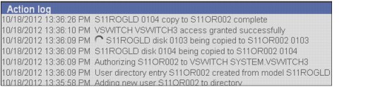
Figure 12-28 Start cloning action log
A window opens that shows the clone that is in the process of being created, as shown in Figure 12-29.

Figure 12-29 Cloning in progress
After all of the clones are created, the user status display shows them all as Inactive, as shown in Figure 12-30.

Figure 12-30 Inactive servers
3. Click a virtual machine name to open the window that is shown in Figure 12-31.

Figure 12-31 Select Operation window
4. Select the Start option, then click Go to activate (XAUTOLOG) the virtual machine. The Alert window opens, as shown in Figure 12-32, in which the start is confirmed.

Figure 12-32 Activate/XAUTOLOG Server
5. To activate many virtual machines, select the check boxes to the left of the machine names that must be activated, then click Action at the top of the list to open the same window. Click Start → Go.
As shown in Figure 12-33, many of the virtual machines are activated. The column to the right of the machine name shows DSC, which indicates that it is running and is disconnected.
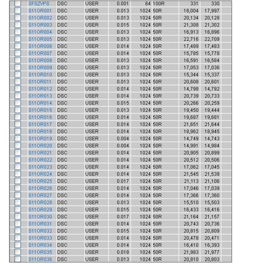
Figure 12-33 Activated servers
12.6 References
The following documents and books were used as reference material in writing this chapter:
•z/VM V6R2 Directory Maintenance Facility Tailoring and Administration Guide, SC24-6190-02
•z/VM V6R2 Systems Management Application Programming, SC24-6234-03
•z/VM and Linux on IBM System z: The Cloud Computing Cookbook for z/VM 6.2 RHEL 6.2 and SLES11 SP2
•SUSE Linux Enterprise Server 11 SP2 Release Notes, which is available at this website:
•Sharing and maintaining Linux under z/VM, REDP-4322
..................Content has been hidden....................
You can't read the all page of ebook, please click here login for view all page.