


Using z/VM Live Guest Relocation to relocate a Linux guest
|
Attention: The following command conventions are used in this chapter:
•z/VM commands are prefixed with ==>
•Linux commands that are running as root are prefixed with #
•Linux commands that are running as non-root are prefixed with $
|
The last release of IBM z/VM 6.2 introduced a major feature named Live Guest Relocation (LGR). This chapter provides information about using LGR in an Oracle environment through two examples by relocating the following components:
•An Oracle Single Instance
•An Oracle RAC cluster
This chapter includes the following topics:
6.1 Overview of z/VM 6.2 features
IBM z/VM 6.2 introduces significant changes to z/VM in the form of multi-system clustering technology, which allows up to four z/VM instances in a single system image (SSI) cluster. This technology is important because it offers you an attractive alternative to vertical growth by adding new z/VM systems. In the past, this capability required duplicate efforts to install, maintain, and manage each system. With SSI, these duplicate efforts are reduced or eliminated.
Support for LGR allows you to move Linux virtual servers without disruption to the business, which helps you to avoid planned outages. The z/VM systems are aware of each other and can use their combined resources. LGR enables you to avoid loss of service because of planned outages by relocating guests from a system that requires maintenance to a system that remains active during the maintenance period. The SSI and LGR technologies offer substantial value and are a major departure from past z/VM practices.
6.1.1 Single System Image feature
The z/VM Single System Image feature (VMSSI) is an optionally priced feature that is new with z/VM Version 6.2. It enables up to four z/VM systems to be configured as members of an SSI cluster, which share the following resources:
•User directory
•DASD volumes
•User minidisks
•Spool files
•Network devices
Members can be on the same or separate Central Processor Complexes (CPCs). They can be first-level or second-level z/VM systems. SSI enables the members of the cluster to be managed as one system, which allows service to be applied to each member of the cluster, thus avoiding an outage to the entire cluster.
6.1.2 LGR
With the IBM z/VM Single System Image, a running Linux on System z virtual machine can be relocated from one member system to any other, a process that is known as LGR. LGR occurs without disruption to the business. It provides application continuity across planned z/VM and hardware outages and flexible workload balancing that allows work to be moved to available system resources.
You might need to relocate a running virtual server for the following reasons:
•Maintaining hardware or software
•Fixing performance problems
•Rebalancing workload
Relocating virtual servers can be useful for load balancing and for moving workload off a physical server or member system that requires maintenance. After maintenance is applied to a member, guests can be relocated back to that member, which allows you to maintain z/VM and keep your Linux on System z virtual servers available.
|
LGR support: Linux on System z is the only guest environment that is supported by LGR. Because the LGR process is not yet certified by Oracle, it is not recommended for use in relocating an active Oracle RAC node.
|
In this chapter, we describe two scenarios of Oracle relocation between two members of a z/VM SSI cluster with an Oracle Single Instance and an Oracle two nodes RAC by stopping each node before their relocations.
6.2 Lab environment
In our lab environment, we set up one z/VM SSI cluster with two members to demonstrate the process of relocation of Oracle environment between these members by using LGR functionality.
6.2.1 Overview of tested two node z/VM SSI cluster
The SSI cluster is named MOPVMSSI. It is composed of two members: MOPVMEM1 and MOPVMEM2, as shown on Figure 6-1.

Figure 6-1 Overview of tested z/VM SSI cluster
Use CP command QUERY SSI to display the information about your SSI cluster, as shown in the following example:
==> query SSI
SSI Name: MOPVMSSI
SSI Mode: Stable
Cross-System Timeouts: Enabled
SSI Persistent Data Record (PDR) device: VMPCOM on 70BE
SLOT SYSTEMID STATE PDR HEARTBEAT RECEIVED HEARTBEAT
1 MOPVMEM1 Joined 11/28/12 18:08:07 11/28/12 18:08:07
2 MOPVMEM2 Joined 11/28/12 18:08:16 11/28/12 18:08:16
3 -------- Available
4 -------- Available
Ready; T=0.01/0.01 18:08:28
6.2.2 Hardware configuration
We used an IBM z196 to host the two LPARs. Each logical partition (LPAR) has 32 GB of memory. We configured the channel-to-channels (CTCs) between each LPAR using inter-system facility for communications (ISFC) as a prerequisite for SSI cluster connection. Each LPAR is connected to the network by using an open system adapter (OSA). Equivalency identifiers (EQIDs) are assigned to the OSAs as a prerequisite for LGR. We shared a pool of direct access storage devices (DASDs) between the two LPARs to host our Oracle environment.
For more information about how to define z/VM resources in your SSI cluster to perform LGR, see An Introduction to z/VM Single System Image (SSI) and Live Guest Relocation (LGR), SG24-8006.
6.2.3 z/VM Software
We installed and customized the following products:
•TCP/IP stack
•IBM Directory Maintenance (DirMaint™)
•Performance Toolkit for z/VM (PERFTK)
6.2.4 Solution that is used to simulate a database workload
During our scenarios, we simulate the client workload on the Oracle database with Swingbench tool (see running in a Linux on System z guest.
For more information about the Swingbench tool, see this website:
6.3 Scenario 1: Relocating an active Oracle single-instance database by using LGR
In this scenario, we describe the steps that are used to relocate an Oracle Single-instance database that is running in a Linux on System z guest between members of a z/VM SSI cluster.
To build this scenario, we installed and set up a Single Instance Oracle 11gR2 database.
Figure 6-2 shows the tested infrastructure.
Figure 6-2 shows the tested infrastructure.

Figure 6-2 Infrastructure for Scenario 1
6.3.1 Setup information
This environment is installed in a single SUSE Linux Enterprise Server 11 SP1 named ITSOORSI with 8 GB of memory and two virtual processors.
Table 6-1 describes the disk layout of the ITSOORSI guest.
Table 6-1 ITSOORSI Disk layout
|
Virtual Device address
|
Disk type
|
Size (MB)
|
Mount
|
|
100
|
3390 mod 9
|
7042
|
/
|
|
101
|
VDisk
|
146
|
First level swap
|
|
102
|
3390 mod 9
|
7042
|
Second-level swap
|
|
200
|
3390 mod 9
|
7042
|
/u01/oracle
|
ITSOORSI is connected to an OSA adapter through a layer 2 virtual switch (VSWITCH) SWCLO. The SWCLO VSWITCH was defined identically in both members of the SSI cluster to allow the LGR.
As a requirement for a guest to by eligible for LGR, we add the option CHPIDVIRTUALIZATION ONE in the user directory, as shown in the following example:
USER ITSOORSI XXXXXX 8G 8G G
COMMAND COUPLE 0D20 SYSTEM SWCLO
COMMAND DEFINE VFB-512 AS 0101 BLK 299008 1
CPU 00 BASE
CPU 01
MACHINE ESA 4
OPTION CHPIDVIRTUALIZATION ONE 2
SCR INA WHI NON STATA RED NON CPOUT YEL NON VMOUT GRE NON INRED TUR
CONSOLE 0009 3215 T
NICDEF 0D20 TYPE QDIO DEVICES 3 LAN SYSTEM SWCLO 3
SPOOL 000C 2540 READER *
SPOOL 000D 2540 PUNCH A
SPOOL 000E 1403 A
MDISK 0100 3390 1 10016 CL2B03 MR 4
MDISK 0102 3390 1 10016 CL2B04 MR 5
MDISK 0200 3390 1 10016 CL2B05 MR 6
The definition of ITSOORSI virtual machine includes the following entries (the numbers in the following list refer to the numbers in the preceding example):
1. First-level swap on Virtual Disk.
2. Sets CHPID virtualization to ONE.
3. Virtual network adapter that is connected to virtual switch SWCLO definition.
4. Minidisk that is used for root.
5. Minidisk that is used for Oracle binaries.
6. Second-level swap on minidisk.
6.3.2 Simulating the client workload
The client workload is simulated with Swingbench running in a Linux on System z guest that is connected on the same network as ITSOORSI.
To configure the access to the database with Oracle Call Interface (OCI), we use the tsnnames.ora file, as shown in the following example:
$ cat tnsnames.ora
# tnsnames.ora Network Configuration File: /u01/oracle/product/11.2.0/dbhome_1/network/admin/tnsnames.ora
# Generated by Oracle configuration tools.
ITSO = 1
(DESCRIPTION =
(ADDRESS = (PROTOCOL = TCP)(HOST = 10.3.58.50)(PORT = 1521)) 2
(CONNECT_DATA =
(SERVER = DEDICATED)
(SERVICE_NAME = ITSO) 3
)
)
This file is used by Oracle clients to retrieve the following information that is required to connect to the database (the numbers in the following list refer to the numbers in the preceding example):
1. Connection name
2. Listener address of the database
3. Database service name
In Swingbench GUI that is shown in Figure 6-3, we define the connection information to access the database (the service name as defined in the tnsnames.ora file), the number of users to generate, and other benchmark runtime parameters.
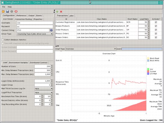
Figure 6-3 Swingbench GUI with parameters used for Scenario 1
We completed the following steps to verify the connectivity between Swingbench tool and Oracle database check:
1. TCP sockets were opened between Swingbench and the Oracle database guest ITSOROSI, as shown in the following example:
# netstat -a | grep swingbench | grep 10.3.58.50
tcp 0 0 swingbench.:60814 10.3.58.50:ncube-lm ESTABLISHED
tcp 0 0 swingbench.:60667 10.3.58.50:ncube-lm ESTABLISHED
tcp 0 0 swingbench.:60631 10.3.58.50:ncube-lm ESTABLISHED
tcp 0 0 swingbench.:60769 10.3.58.50:ncube-lm ESTABLISHED
tcp 0 0 swingbench.:60731 10.3.58.50:ncube-lm ESTABLISHED
tcp 0 0 swingbench.:60776 10.3.58.50:ncube-lm ESTABLISHED
tcp 0 0 swingbench.:60749 10.3.58.50:ncube-lm ESTABLISHED
tcp 0 0 swingbench.:60652 10.3.58.50:ncube-lm ESTABLISHED
tcp 0 0 swingbench.:60700 10.3.58.50:ncube-lm ESTABLISHED
2. TCP sockets were opened between Swingbench and ITSOROSI, as shown in the following example:
# netstat -a | grep swingbench | grep 10.3.58.50 | wc -l
200
A total of 200 connections are opened, which correspond to the 200 users that are defined in Swingbench.
6.3.3 Relocating an Oracle guest
|
Class A user needed: We run the z/VM commands from a class A user ID (MAINT for example) of MOPVMEM1
|
Complete the following steps to perform guest relocation:
1. Check ITSOORSI is running in MOPVMEM1, as shown in the following example:
==> QUERY ITSOORSI AT ALL
MOPVMEM1 : ITSOORSI - DSC
2. Test if it is eligible for relocation to MOPVMEM2, as shown in the following example:
==> VMRELOCATE TEST ITSOORSI TO MOPVMEM2
User ITSOORSI is eligible for relocation to MOPVMEM2
Ready; T=0.01/0.01 17:51:24
3. Perform the effective relocation to MOPVMEM2, as shown in the following example:
==> VMRELOCATE MOVE ITSOORSI TO MOPVMEM2
Relocation of ITSOORSI from MOPVMEM1 to MOPVMEM2 started
User ITSOORSI has been relocated from MOPVMEM1 to MOPVMEM2
Ready; T=0.01/0.01 17:52:31
4. Verify that the relocation was successful, as shown in the following example:
==> QUERY ITSOORSI AT ALL
MOPVMEM2 : ITSOORSI - DSC
We can see the quiesce time of the guest by running a ping command to the gateway each second during the relocation process. In our test, ITSOORSI is freezing for about 6 seconds (between 16:55:03 and 16:55:10), as shown in the following example:
# ping 10.3.58.254 | awk '/64/ {"date" | getline date ; print $0, " " date ; close("date")}'
64 bytes from 10.3.58.254: icmp_seq=54 ttl=255 time=0.538 ms Mon Dec 3 16:55:01 CET 2012
64 bytes from 10.3.58.254: icmp_seq=55 ttl=255 time=7.77 ms Mon Dec 3 16:55:02 CET 2012
64 bytes from 10.3.58.254: icmp_seq=56 ttl=255 time=0.499 ms Mon Dec 3 16:55:03 CET 2012
64 bytes from 10.3.58.254: icmp_seq=58 ttl=255 time=0.561 ms Mon Dec 3 16:55:10 CET 2012
64 bytes from 10.3.58.254: icmp_seq=59 ttl=255 time=0.590 ms Mon Dec 3 16:55:11 CET 2012
64 bytes from 10.3.58.254: icmp_seq=60 ttl=255 time=0.797 ms Mon Dec 3 16:55:12 CET 2012
In the Swingbench GUI, we can observe that during the quiesce time, the transactions froze (as shown in Figure 6-4) in the Transaction per seconds graph. However, all of the users remained connected to the database.

Figure 6-4 Swingbench GUI during relocation in Scenario 1
6.4 Scenario 2: Relocating an Oracle RAC inactive node by using LGR
In this section, we describe the steps that are used to relocate a two nodes Oracle RAC environment running in Linux guests between members of a z/VM SSI cluster.
Because the Live Guest Relocation on an active RAC node was not certified yet, complete the following steps:
1. Stop the Oracle cluster process on one of the nodes (leaving the Linux active). The node leaves the Oracle cluster.
2. Relocate this Linux guest to the other z/VM using LGR.
3. Restart the Oracle cluster on the Linux guest. It rejoins the Oracle cluster.
4. Stop the Oracle cluster process on the second node.
5. Relocate it to the other z/VM.
6. Restart Oracle cluster processes on the second Linux guest.
To build this scenario, we installed and set up a two-node 11g R2 Oracle RAC database and configured it with Oracle application failover technology to provide continuous operation of the database and balancing the client connection to the other node during relocation.
When one of the nodes is shut down, the clients are automatically reconnected to the survival node. Figure 6-5 shows the tested infrastructure.
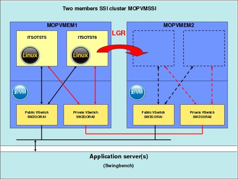
Figure 6-5 Infrastructure for Scenario 2
6.4.1 Setup information
We defined two Linux virtual machines, ITSOTST5 and ITSOTST6, to host the two nodes of Oracle RAC. Both machines were configured with 8 GB of memory, two virtual processors, and ran SUSE Linux Enterprise Server 11 SP1, as shown in the following example:
USER ITSOTST5 XXXXXX 8G 8G G
COMMAND COUPLE 0D40 SYSTEM SWZGORA1
COMMAND COUPLE 0D50 SYSTEM SWZGORA2
COMMAND DEFINE VFB-512 AS 0101 BLK 299008 1
CPU 00 BASE
CPU 01
MACHINE ESA 4
OPTION CHPIDV ONE 2
SCR INA WHI NON STATA RED NON CPOUT YEL NON VMOUT GRE NON INRED TUR
CONSOLE 0009 3215 T
NICDEF 0D40 TYPE QDIO DEVICES 3 LAN SYSTEM SWZGORA1 3
NICDEF 0D50 TYPE QDIO DEVICES 3 LAN SYSTEM SWZGORA2 3
SPOOL 000C 2540 READER *
SPOOL 000D 2540 PUNCH A
SPOOL 000E 1403 A
MDISK 0100 3390 1 10016 CL2B06 MR 4
MDISK 0102 3390 1 10016 CL2B07 MR 5
MDISK 0200 3390 1 10016 CL2B08 MR 6
MDISK 0400 3390 1 10016 CL2B09 MW 7
MDISK 0401 3390 1 10016 CL2B0A MW 7
MDISK 0402 3390 1 10016 CL2B0B MW 7
MDISK 0300 3390 1 10016 CL2B0C W 8
MDISK 0301 3390 1 10016 CL2B0D W 8
MDISK 0302 3390 1 10016 CL2B0E W 8
MDISK 0303 3390 1 10016 CL2B0F W 8
MDISK 0304 3390 1 10016 CL2B10 W 8
USER ITSOTST6 XXXXXX 8G 8G G
COMMAND COUPLE 0D40 SYSTEM SWZGORA1
COMMAND COUPLE 0D50 SYSTEM SWZGORA2
COMMAND DEFINE VFB-512 AS 0101 BLK 299008 1
CPU 00 BASE
CPU 01
MACHINE ESA 4
OPTION CHPIDV ONE 2
SCR INA WHI NON STATA RED NON CPOUT YEL NON VMOUT GRE NON INRED TUR
CONSOLE 0009 3215 T
NICDEF 0D40 TYPE QDIO DEVICES 3 LAN SYSTEM SWZGORA1 3
NICDEF 0D50 TYPE QDIO DEVICES 3 LAN SYSTEM SWZGORA2 3
SPOOL 000C 2540 READER *
SPOOL 000D 2540 PUNCH A
SPOOL 000E 1403 A
LINK ITSOTST5 0400 0400 MW 7
LINK ITSOTST5 0401 0401 MW 7
LINK ITSOTST5 0402 0402 MW 7
MDISK 0100 3390 1 10016 CL2B11 MR 4
MDISK 0102 3390 1 10016 CL2B12 MR 5
MDISK 0200 3390 1 10016 CL2B13 MR 6
MDISK 0300 3390 1 10016 CL2B14 W 8
MDISK 0301 3390 1 10016 CL2B15 W 8
MDISK 0302 3390 1 10016 CL2B16 W 8
MDISK 0303 3390 1 10016 CL2B17 W 8
MDISK 0304 3390 1 10016 CL2B10 W 8
The definition of ITSOTST5 and ITSOTST6 virtual machines includes the following entries (the following numbers correspond to the numbers in the preceding example):
1. First-level swap on Virtual Disk.
2. Sets CHPID virtualization to ONE.
3. Virtual network adapters definition.
4. Minidisk that is used for root file system.
5. Second-level swap on minidisk.
6. Minidisk that is used for Oracle binaries.
7. Disks that are used for Oracle Grid installation (for ITSOTST6, these are links to ITSOTST5 disks).
8. Disks that are used by ASM.
By using this infrastructure, we installed Oracle RAC with an Oracle GRID infrastructure (Oracle ASM and Oracle Clusterware) to provide a High Availability (HA) environment.
For more information about High Availability, see Chapter 9, “High Availability and Disaster Recovery environment for Oracle” on page 179.
6.4.2 Network configurations
Various network configurations are certified for an Oracle RAC running under z/VM. For more information, see Chapter 3, “Network connectivity options for Oracle on Linux on IBM System z” on page 29.
In Scenario 2, we choose to create the following virtual switches (vSwitch) in each z/VM:
•Public vSwitch SWZGORA1 to access the RAC from outside
•Private vSwitch SWZGORA2 for the interconnect network
|
Tip: Layer 2 HiperSockets are supported for LGR. If your SSI members run in the same physical machine, we recommend the use of a HiperSockets interface instead of a VSWITCH for the private interconnect network to use the unique network architecture of IBM System z.
For more information, see Chapter 9, “High Availability and Disaster Recovery environment for Oracle” on page 179.
|
An Oracle RAC environment requires a specific Linux network configuration. Each node needs to have at least the following IP addresses:
•Public interface IP used to reach the Linux guest through SSH and perform installation, configuration, management, and maintenance of the Operating System and Oracle RAC node.
•Private interconnect interface IP that is used for the communication between the nodes of the RAC. Generally, this connection is on a private and non-routable network.
•Oracle Virtual IP (VIP) defined on the same subnetwork as the public IP. This interface is automatically created during the Oracle RAC installation.
With Oracle RAC 11g, you can configure Single Client Access Name (SCAN) listener, which provides a unique name to connect to the cluster database. The client connection descriptor contains only the SCAN listener name and not all the local listener addresses of each node. Oracle automatically redirects the client connection to an available node. If a node fails or is unreachable, Oracle redirects clients’ connections to a healthy node. This functionality is a part of the Oracle load balancing and failover capabilities. Oracle recommends to set up a DNS SCAN with three SCAN IP addresses defined on it and to add an entry for this DNS in the /etc/host file of each node. In our demonstration environment, we do not set up a DNS to provide the SCAN IPs. Instead, we provide a single SCAN IP directly on the host file of each node.
We set up the network configuration of ITSOTST5 as shown in Example 6-1.
Example 6-1 Network configuration of ITSOTST5
itsotst5:~ # cat /etc/hosts
#itsotst5 public IP
10.3.58.51 itsotst5.mop.ibm.com itsotst5
#itsotst5 interconnect IP
10.7.17.10 itsotst5-priv
#itsotst5 virtual IP
10.3.58.55 itsotst5-vip
#itsotst6 public IP
10.3.58.52 itsotst6.mop.ibm.com itsotst6
#itsotst6 interconnect IP
10.7.17.11 itsotst6-priv
#itsotst5 private IP
10.3.58.56 itsotst6-vip
#SCAN listener IP
10.3.58.57 itsotst
We configured the SCAN listener ITSOTST with the IP address 10.3.58.57, and the nodes as described in Table 6-2.
Table 6-2 Network configuration of the RAC
|
Hostname
|
Public IP
|
Virtual IP
|
Interconnect IP
|
|
ITSOTST5
|
10.3.58.51
|
10.3.58.55
|
10.7.17.10
|
|
ITSOTST6
|
10.3.58.52
|
10.3.58.56
|
10.7.17.11
|
6.4.3 Client configuration of Transparent Application Failover
Before relocating a Linux node, we have to shut down the Oracle processes that are running on it. To ensure that all of the users that are connected to the falling node do not lose their connections to the database, we have to provide connection recovery capabilities. For more information about HA solutions on Oracle, see Chapter 9, “High Availability and Disaster Recovery environment for Oracle” on page 179.
In Scenario 2, we used the Transparent Application Failover (TAF). This solution provides client recovery capabilities in case of failed connection by restarting the query in a healthy node. If the failure happens during a transaction, it is rolled back automatically.
The TAF is configured on the client side (in our environment, this is where Swingbench is running) in the tnsnames.ora file. We enter network information and a database service name to reach the database from the client side and different information for the TAF configuration, as shown in the following example:
$ cat /u01/oracle/product/11.2.0/dbhome_1/network/admin/tnsnames.ora
ITSOCLUSTER = 1
(DESCRIPTION =
(LOAD_BALANCE = on) 2
(FAILOVER = on)
(ADDRESS = (PROTOCOL = TCP)(HOST = 10.3.58.57)(PORT = 1521)) 3
(CONNECT_DATA =
(SERVER = DEDICATED)
(SERVICE_NAME = ITSORAC) 4
(FAILOVER_MODE=(TYPE=SELECT)(METHOD=BASIC)) 5
)
)
This example included the following components (the following numbers correspond to the numbers that are shown in the preceding example):
1. The connection name.
2. By setting LOAD_BALANCE=on, Oracle RAC distributes the users connection fairly across the different nodes accessing the same database.
3. The address of the SCAN listener.
4. The database service name.
5. The definition of the FAILOVER_MODE to provide client recovery capabilities when a node is shut down.
|
Tip: Make sure that the remaining node (or nodes) can handle all of the connections that are redirected by the TAF from the failed node.
|
6.4.4 Simulating the client workload
The client workload is simulated with Swingbench running in a Linux on System z guest connected on the same network as the Oracle RAC nodes. In the Swingbench GUI that is shown in Figure 6-6, we define the connection information to access the database (the service name as defined in the tnsnames.ora file), the number of users to generate, and other benchmark runtime parameters.

Figure 6-6 Swingbench GUI with parameters used for Scenario 2
In accordance with our TAF configuration, Swingbench generates the workload of 100 users using the single IP address of the SCAN Listener and RAC balances the connection between the two nodes.
To verify the connectivity between Swingbench tool and Oracle RAC, check the following components:
•The state of the nodes, as shown in the following example:
itsotst5:~ # su - grid
grid@itsotst5:/home/grid> crsctl status server
NAME=itsotst5
STATE=ONLINE
NAME=itsotst6
STATE=ONLINE
•The TCP sockets that are opened between Swingbench and the Oracle RAC, as shown in the following example:
swingbench:~ # netstat -a | grep swingbench | grep 10.3.58.5
tcp 0 0 swingbench.:46789 10.3.58.56:ncube-lm ESTABLISHED
tcp 0 0 swingbench.:46777 10.3.58.56:ncube-lm ESTABLISHED
tcp 0 0 swingbench.:59034 10.3.58.55:ncube-lm ESTABLISHED
tcp 0 0 swingbench.:59030 10.3.58.55:ncube-lm ESTABLISHED
tcp 0 0 swingbench.:59042 10.3.58.55:ncube-lm ESTABLISHED
tcp 0 0 swingbench.:59038 10.3.58.55:ncube-lm ESTABLISHED
tcp 0 0 swingbench.:59026 10.3.58.55:ncube-lm ESTABLISHED
tcp 0 0 swingbench.:46785 10.3.58.56:ncube-lm ESTABLISHED
tcp 0 0 swingbench.:46781 10.3.58.56:ncube-lm ESTABLISHED
tcp 0 0 swingbench.:46773 10.3.58.56:ncube-lm ESTABLISHED
•The number of TCP sockets that are opened between Swingbench and ITSOTST5, as shown in the following example:
swingbench:~ # netstat -a | grep swingbench | grep 10.3.58.55 | wc -l
50
There are 50 connections that are open, which corresponds to the half of the 100 users that are defined in Swingbench.
•The number of TCP sockets that are opened between Swingbench and ITSOTST6, as shown in the following example:
swingbench:~ # netstat -a | grep swingbench | grep 10.3.58.56 | wc -l
50
There are 50 connections that are open, which corresponds to the half of the 100 users that are defined in Swingbench.
6.4.5 Stopping Oracle on one node
In this phase, we complete the following steps to stop the Oracle cluster on ITSOTST6 and verify that the connections from Swingbench were rerouted to ITSOTST5:
1. Stop the Oracle cluster on ITSOTST6, as shown in the following example:
itsotst6:/home/grid # crsctl stop cluster
CRS-2673: Attempting to stop 'ora.crsd' on 'itsotst6'
CRS-2790: Starting shutdown of Cluster Ready Services-managed resources on 'itsotst6'
CRS-2673: Attempting to stop 'ora.DGOCRVOT.dg' on 'itsotst6'
CRS-2673: Attempting to stop 'ora.itsorac.db' on 'itsotst6'
CRS-2673: Attempting to stop 'ora.LISTENER.lsnr' on 'itsotst6'
CRS-2673: Attempting to stop 'ora.LISTENER_RDBMS.lsnr' on 'itsotst6'
…
CRS-2677: Stop of 'ora.cluster_interconnect.haip' on 'itsotst6' succeeded
CRS-2673: Attempting to stop 'ora.cssd' on 'itsotst6'
CRS-2677: Stop of 'ora.cssd' on 'itsotst6' succeeded
2. Check the status of the cluster during the process to stop the ITSOTST6 node, as shown in the following example:
grid@itsotst5:/home/grid> # crsctl status server
NAME=itsotst5
STATE=ONLINE
NAME=itsotst6
STATE=LEAVING
3. Recheck the status of the cluster after successfully stopping the ITSOTST6 node, as shown in the following example:
grid@itsotst5:/home/grid> # crsctl status server
NAME=itsotst5
STATE=ONLINE
4. Check the number of TCP sockets that are opened between Swingbench and ITSOTST5, as shown in the following example:
swingbench:~ # netstat -a | grep swingbench | grep 10.3.58.55 | wc -l
100
As shown in Figure 6-7, when the ITSOTST6 is stopped, transaction per seconds froze for a short time on all the RAC. Some transactions are rolled back by the TAF and automatically balanced to the second node. However, all users stay connected to the database.

Figure 6-7 Swingbench GUI during relocation in Scenario 2
6.4.6 Relocating the Oracle guest
|
Class A user needed: We run the z/VM commands from a class A user ID (for example, MAINT) of MOPVMEM1.
|
Complete the steps to perform guest relocation:
1. Check ITSOTST5 is running in MOPVMEM1, as shown in the following example:
==> QUERY ITSOTST5 AT ALL
MOPVMEM1 : ITSOTST5 - DSC
2. Check ITSOTST6 is running in MOPVMEM1, as shown in the following example:
==> QUERY ITSOTST6 AT ALL
MOPVMEM1 : ITSOTST6 - DSC
3. Test if the ITSOTST6 can be relocated to MOPVMEM2, as shown in the following example:
==> VMRELOCATE TEST ITSOTST6 TO MOPVMEM2
User ITSOTST6 is eligible for relocation to MOPVMEM2
Ready; T=0.01/0.01 17:51:24
4. Relocate ITSOTST6 to MOPVMEM2, as shown in the following example:
==> VMRELOCATE MOVE ITSOTST6 TO MOPVMEM2
Relocation of ITSOTST6 from MOPVMEM1 to MOPVMEM2 started
User ITSOTST6 has been relocated from MOPVMEM1 to MOPVMEM2
Ready; T=0.01/0.01 17:52:31
5. Verify that the relocation was successful, as shown in the following example:
==> QUERY ITSOTST6 AT ALL
MOPVMEM2 : ITSOTST6 - DSC
6.4.7 Restarting Oracle on relocated guest
In this phase, we complete the following steps to restart the Oracle node on ITSOTST6 node and check the status of the cluster:
1. Start the Oracle node on ITSOTST6, as shown in the following example:
itsotst6:/home/grid # crsctl start cluster
CRS-2672: Attempting to start 'ora.cssdmonitor' on 'itsotst6'
CRS-2676: Start of 'ora.cssdmonitor' on 'itsotst6' succeeded
CRS-2672: Attempting to start 'ora.cssd' on 'itsotst6'
CRS-2672: Attempting to start 'ora.diskmon' on 'itsotst6'
CRS-2676: Start of 'ora.diskmon' on 'itsotst6' succeeded
…
CRS-2676: Start of 'ora.asm' on 'itsotst6' succeeded
CRS-2672: Attempting to start 'ora.crsd' on 'itsotst6'
CRS-2676: Start of 'ora.crsd' on 'itsotst6' succeeded
2. Check the status of the cluster during Oracle start on ITSOTST6, as shown in the following example:
grid@itsotst5:/home/grid> # crsctl status server
NAME=itsotst5
STATE=ONLINE
NAME=itsotst6
STATE=JOINING
3. Recheck the status of the cluster after successful Oracle start on ITSOTST6, as shown in the following example:
grid@itsotst5:/home/grid> crsctl status server
NAME=itsotst5
STATE=ONLINE
NAME=itsotst6
STATE=ONLINE
After ITSOTST6 rejoins the cluster, the 100 users on ITSOTST5 cannot be rebalanced between the two nodes. Only new user connections are automatically balanced.
We can apply the steps that are described in Scenario 2 for Oracle cluster on ITSOTST5, relocate it with LGR, and then restart it.
By using Oracle failover capacities and z/VM LGR, we relocated all of our Oracle RAC infrastructure in a new z/VM with only a few seconds of interruption of services during the relocation and with no loss of users connections, queries, or transaction to the database.
..................Content has been hidden....................
You can't read the all page of ebook, please click here login for view all page.