
In Chapter 4, Creating Solids and Surfaces from 2D, we introduced how to create surfaces by applying EXTRUDE and other commands to linear objects. This chapter is about all types of surfaces and meshes.
The topics covered in this chapter are:
- Identifying types of surfaces and their applications
- How to create and edit procedural surfaces
- How to create and edit NURBS surfaces
- How to create and edit meshes
- How to create meshes based on 3D faces
- Analyzing surfaces curvature
Surfaces and meshes are 3D objects with zero thickness. Most of the time, when modeling in 3D, we apply solids, which give us much better precision; since Version 2010, surfaces and meshes are also available, and can be used for complex and conceptual models. These objects are divided into the following categories:
- Procedural surfaces: These are surfaces created from linear objects, such as
EXTRUDE,REVOLVE, orSWEEP, as we have seen in Chapter 4, Creating Solids and Surfaces from 2D. These surfaces could or could not maintain association with original linear objects. We will present several other commands for creating procedural surfaces. - NURBS surfaces: Non-Uniform Rational B-Splines (NURBS) surfaces are based on splines and are mainly modified by control vertices. This type of surfaces is mainly applied in the aeronautical, automotive, mould, or any industry with free-form shapes.
- Meshes: These objects, also called tessellation meshes, are not really surfaces but allow creating smooth 3D objects.
- Polyface meshes: These are the oldest AutoCAD 3D objects, long before solids, and are based on 3D faces.

Procedural surfaces can be created from linear objects, with some commands presented in Chapter 4, Creating Solids and Surfaces from 2D, such as EXTRUDE or SWEEP, also with PLANESURF, presented in Chapter 5, 3D Primitives and Conversions, and with SURFNETWORK, presented next section. These surfaces can also be obtained from other surfaces, applying known operations such as blend, fillet, or offset. Included are also two editing commands and a command to create solids from surfaces.
The SURFACEMODELINGMODE variable must have value 0. With value 1, NURBS surfaces are created instead when applying next commands. The SURFU and SURFV variables control the surface isolines density in the first and second directions and can be modified any time with the PROPERTIES palette.
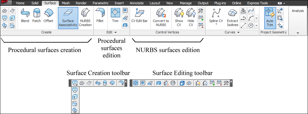
Most procedural and NURBS surface commands are on the ribbon, Surface panel, on the Draw/Modeling and Modify/Surface Editing menu bars, and on the Surface Creation and Surface Editing toolbars.
In Chapter 4, Creating Solids and Surfaces from 2D we already introduced several commands for creating procedural surfaces. Let's summarize them:
EXTRUDE(aliasEXT): This command creates surfaces by applying an extrusion height to open linear objects or closed linear objects if the MOde option is set to SUrface.REVOLVE(aliasREV): This command creates surfaces by rotating open linear objects, or closed linear objects if the MOde option is set to SUrface, around an axis.SWEEP: This command creates a surface by extruding an open section, or closed section if the MOde option is set to SUrface, along a path.LOFT: This command creates surfaces from the selection of two or more open linear cross sections or closed linear cross sections if the MOde option is set to SUrface.
When applying these commands from the Surface Creation toolbar or ribbon, Surface panel, the MOde option is already set to SUrface. These commands also generate surfaces if applied to edges of solids or surfaces (selected by pressing the Ctrl key).
The SURFACEASSOCIATIVITY variable controls if surfaces maintain an association to original linear objects. If the value is 0, association is not maintained; if the value is 1 (default) association is maintained. This variable can be directly manipulated on the ribbon.
Two other commands, presented in Chapter 5, 3D Primitives and Conversions, also allow creating surfaces:
PLANESURF: This command creates planar surfaces defined by two opposite corners or delimited by one or more existing objects. We can select lines, arcs, circles, ellipses, 2D polylines, 3D planar polylines, planar splines, regions, and 3D faces. For each closed object or set of objects that form a closed boundary, a surface is created.CONVTOSURFACE: This command converts the following objects to surfaces, namely 2D open polylines with nonzero thickness, lines and arcs with nonzero thickness, regions, planar 3D faces, 2D solid objects (SOLID), 3D solids and 3D meshes.
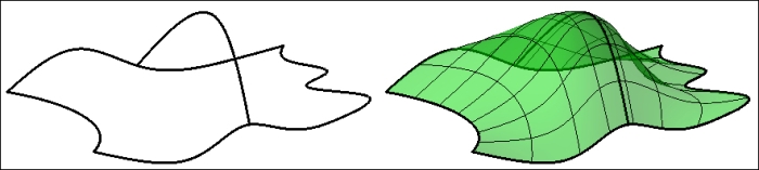
The SURFNETWORK command (no alias) allows you to create a surface from two sets of open linear objects that specify a boundary and net in two directions. The command starts by prompting the objects in the first direction:
Command: SURFNETWORK
Select curves or surface edges in first direction: Selection
We press Enter to finish the first selection:
Select curves or surface edges in first direction: Enter
We select the second set of objects:
Select curves or surface edges in second direction: Selection
When pressing Enter, the surface is created:
Select curves or surface edges in second direction: Enter
Several commands are presented that allow you to create surfaces from existing surfaces. Bulge and continuity are two options frequently used when creating or adjusting surfaces.
The two important surface properties are continuity and bulge. These properties can be controlled when creating the surface (with options or grips) or later, with grips or the PROPERTIES palette.
Continuity defines the transition between surfaces and AutoCAD allows three possibilities:
G0: This is just position, coincident edges between the two surfaces, with creaseG1: This is position and tangency; there is a smooth transition (no crease) between surfaces but can have sudden changes in curvatureG2: This is position, tangency, and curvature; the two surfaces share the same curvature or a similar radius at the transition
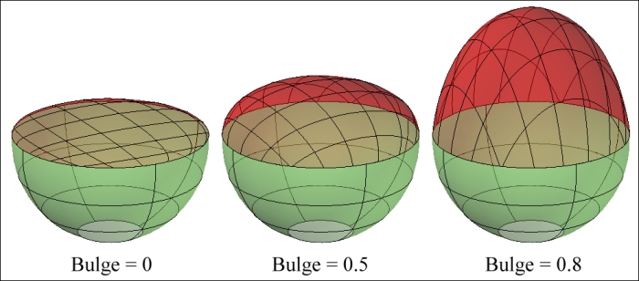
Bulge controls the surface curvature at transition edges, with a value between 0 and 1.
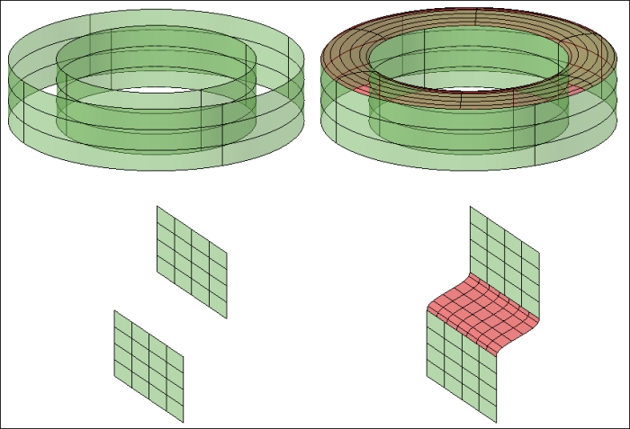
The SURFBLEND command (no alias) creates a surface connecting two existing surfaces. The command just prompts for the selection of two sets of edges from the surfaces to connect and allows for controlling continuity and bulge:
Command: SURFBLEND
Information is displayed with default continuity and bulge values:
Continuity = G1 - tangent, bulge magnitude = 0.5
The command prompts for edges selection on the first surface, finished by pressing Enter. The CHain option allows for selecting all connected edges by selecting only one:
Select first surface edges to blend or [CHain]: Selection
Select first surface edges to blend or [CHain]: Enter
The command prompts for edges selection on the second surface, finished by pressing Enter:
Select second surface edges to blend or [CHain]: Selection
Select second surface edges to blend or [CHain]: Enter
We press Enter to accept the surface or apply options to control continuity or bulge values:
Press Enter to accept the blend surface or [CONtinuity/Bulge magnitude]: Enter
The SURFPATCH command (no alias) creates a surface that closes a hole or an opening. By default, the command prompts for the selection of edges that limits the opening:
Command: SURFPATCH
Information is displayed with default continuity and bulge values:
Continuity = G0 - position, bulge magnitude = 0.5
The command prompts for edges selection on the first surface, finished by pressing Enter. The CHain option allows for selecting all connected edges by selecting only one, and the CUrves option allows selecting linear entities:
Select surface edges to patch or [CHain/CUrves] <CUrves>: Selection
Select surface edges to patch or [CHain/CUrves] <CUrves>: Enter
We press Enter to accept the surface or apply options to control continuity or bulge values. The Guides option allows selecting guided lines that mould the surface:
Press Enter to accept the patch surface or [CONtinuity/Bulge magnitude/Guides]: Enter

The SURFEXTEND command (no alias) creates a surface by extending existing surfaces from selected edges. By default, the command prompts for edges selection and distance:
Command: SURFEXTEND
Information is displayed with the default values for the Modes option:
Modes = Extend, Creation = Append
We select one or more edges from which surfaces will extend:
Select surface edges to extend: Selection
Select surface edges to extend: Enter
We specify the extension distance. The Expression option allows entering a mathematical expression. The Modes option includes the possibility of stretching the surface (Stretch), instead of extending (Extend), and merging into the existing surface (Merge), instead of creating a new one (Append):
Specify extend distance [Expression/Modes]: Value

The SURFOFFSET
command (no alias) creates surfaces parallel to the selected surfaces.
By default, we select surfaces and specify a distance:
Command: SURFOFFSET
Information with the default value for the Connect option:
Connect adjacent edges = No
The command prompts for the surfaces' selection:
Select surfaces or regions to offset: Selection
Select surfaces or regions to offset: Enter
Small arrows, normal to surfaces, are displayed indicating the offset direction. By default, we only need to specify a distance. The Flip direction option allows you to invert the direction. The
Both sides option applies offset in both directions. The Solid option, creates a solid corresponding to the volume between the surfaces, similar to the THICKEN command application. The Connect option also connects offset surfaces if original surfaces are connected:
Specify offset distance or [Flip direction/Both sides/Solid/Connect/Expression] <0.0000>: Value

The SURFFILLET command (no alias) creates a fillet surface between two existing surfaces. The fillet radius is adjusted by grip or option.
Command: SURFFILLET
Information with default values for command options:
Radius = 6.0000, Trim Surface = yes
The command prompts for the selection of the first surface and, then, the second surface:
Select first surface or region to fillet or [Radius/Trim surface]: Selection
Select second surface or region to fillet or [Radius/Trim surface]: Selection
A preview surface is displayed with a grip for controlling fillet radius. The Radius option allows defining a value for radius. The Trim surfaces option trims and extends, or not, original surfaces to meet the fillet surface.
Press Enter to accept the fillet surface or [Radius/Trim surfaces]: Enter

Frequently we need to trim surfaces. Related to that, we presented the PROJECTGEOMETRY command in Chapter 7, Editing Solids and Surfaces. If the SURFACEAUTOTRIM variable has value 1, that command, besides projecting linear objects, also cuts surfaces and solids. Now we refer two commands specific to that operation.
The SURFTRIM command (no alias) cuts surfaces with other surfaces, linear objects, or regions. By default, the command prompts for surfaces or regions to trim, the trimming geometry, and the side that will be trimmed. Trimmed surfaces can be restored with the next command.
Command: SURFTRIM
Information with default values for command options:
Extend surfaces = Yes, Projection = Automatic
The command prompts for surfaces or regions to be trimmed. The Extend option controls if intersecting objects can be extended for boundaries definition, or must really intersect. The PROjection direction defines how trimming geometry is projected onto surfaces to trim, may be Automatic, View, UCS, or None:
Select surfaces or regions to trim or [Extend/PROjection direction]: Selection
Select surfaces or regions to trim or [Extend/PROjection direction]: Enter
The command prompts for objects (surfaces, regions, or linear objects) that define trimming boundaries:
Select cutting curves, surfaces or regions: Selection
Select cutting curves, surfaces or regions: Enter
We specify a point on the area or side to be trimmed. The prompt is repeated until the Enter key is pressed. The Undo option undoes last trim:
Select area to trim [Undo]: Point
Select area to trim [Undo]: Enter

The SURFUNTRIM command (no alias) restores parts of trimmed surfaces. It only prompts for the selection of edges resulting from trimmed operations. The SURface option allows restoring all trimmed parts on the selected surfaces:
Command: SURFUNTRIM
Select edges on surface to un-trim or [SURface]: Selection
Select edges on surface to un-trim or [SURface]: Enter
From a 2D simple drawing, we are going to model a building with surfaces by following these steps:
- Open the drawing
A3D_12_01.DWG. The layers are already created. - Active the
3D-Wallslayer. Extrude the hexagon by6units, as surface (with MOde option set to Surface, or applying the Surface Creation toolbar or Surface tab). Extrude the two lines by3units. - Create an inner surface, apply the
SURFOFFSETcommand, select the hexagonal surface, change the Flip direction option, and specify an offset distance of12units. - We apply
SURFFILLETwith a radius of4units to the corner between the two straight surfaces. - Activating the X-Ray visual style, the model should look like the next diagram:

- Activate the
3D-Roofslayer. Applying theSURFBLENDcommand, specify the CHain option and select an edge on the outer surface. Then, again with the CHain option, select an edge on the inner surface and press Enter to accept the blended surface. - To cut the parts of the straight surfaces that are inside the outer surface, the
SURFTRIMcommand should be applied. Select both straight surfaces, press Enter, and select the outer surface as cutting surface. Finally, mark on the parts of the straight surfaces that will be cut. - To create a roof on the entrance of the building, we need an extra surface. Draw a line between top endpoints of the straight surfaces and extrude it with
-1. - Now, apply the
SURFPATCHcommand, selecting all edges that form the closed loop, and confirm a flat patch surface. - Now delete the small extruded surface.
- Finally, trim the outer surface with the
SURFTRIMcommand, selecting the outer surface, as cutting surfaces we select the straight surfaces and the entrance roof, and specify the area to be trimmed. - Freeze the 2D layer.
- Save the drawing with the name
A3D_12_01final.DWG.
The next command does not create or edit surfaces but is closely associated.
The SURFSCULPT command (no alias) creates a solid from a closed volume, delimited by surfaces, regions, meshes, or existing solids. Surfaces and regions used in this creation are deleted and solids are united to the resulting solid. Surfaces must be G0, that is, with no tangencies between them:
Command: SURFSCULPT
Information about the SMOOTHMESHCONVERT variable (used if meshes are included):
Mesh conversion set to: Smooth and optimized.
The command only prompts for surfaces, solids, regions, and meshes that completely enclose a volume:
Select surfaces or solids to sculpt into a solid: Selection
Select surfaces or solids to sculpt into a solid: Enter

Let's apply this command to create a solid from the model created in the Exercise 12.1 section:
- Open the drawing
A3D_12_02.DWG. - To have an enclosed volume, the model must be capped below. So we have to create
PLANESURFinvolving all model base. - Now, it's only applying the
SURFSCULPTcommand and selecting all objects. The solid is created and all surfaces are deleted. - Save the drawing with the name
A3D_12_02final.DWG.