
If we changed the view direction, how can we come back to the plan view? Or see the model from another orthographic view? And how to save that view so that we can restore it anytime? These operations and the creation of cameras are presented next.
Predefined in AutoCAD, we have six orthographic views (Top, Bottom, Front, Back, Left, and Right) and four isometric views (Southwest Isometric, Southeast Isometric, Northeast Isometric, and Northwest Isometric). There are several ways to access them; some may activate another coordinate system.
The view cube, available since Version 2009, is a navigation tool placed by default in the viewport's top-right corner. When inactive, it is partially transparent. With this tool we can click on a face to activate the respective orthographic view. For instance, if we want to come to the plan or top view, we click the top face. We can also drag the mouse over the view cube to orbit the drawing, click a vertex to activate that isometric view, or click an edge to view the model from that edge.
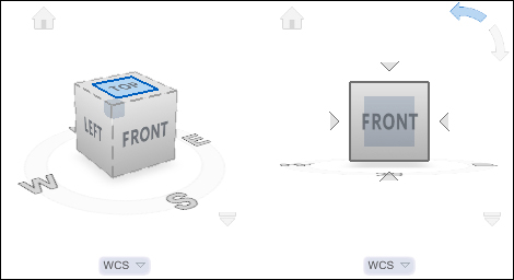
The view cube's properties are controlled by the shortcut menu (right-click over the cube) or the NAVVCUBE command. The small button below allows you to choose world coordinate system
(WCS) or a user coordinate system. With the view cube, clicking on a face neither activates the corresponding coordinate system nor processes a ZOOM command's Extents option in the model.
The access to the predefined orthographic and isometric views can be found on the ribbon by going to the Home | View tab and clicking on the second drop list.
If we use a workspace based on toolbars, the View toolbar contains these predefined views.

The ZOOM command's Extents option is processed in the scene when using these tools. Choosing an orthographic view, AutoCAD also activates the corresponding orthographic coordinate system, so the working XY plane becomes parallel to the view. This behavior may be undesirable and can be turned off by assigning the value 0 to the UCSORTHO variable. This variable is saved in the registry and doesn't depend on drawings.
Since Version 2012, in the top-left corner of the viewport, by default, there are three controls. The second one allows the activation of the predefined or saved views. Viewport controls are presented later.
This command directly activates the Top view for the current coordinate system (default), any saved coordinate system, or the world coordinate system. It processes the ZOOM command's Extents option in the model.
Two more commands are available for changing the viewing direction:
VPOINT: This command (alias-VP) defines the viewing direction by a vector that connects a point to the origin. The command just asks for this point. For instance, looking at the origin, 0,0,1 indicates that we are on the Z axis; it means this is the top view. TheZOOMcommand's Extents option is always processed, so 0,0,2 will give exactly the same result. 1,1,1 means that we are at the same distance from all the positive axes (Northeast Isometric). This command has the advantage of replicating a precise non-orthographic view. The other options are less important.DDVPOINT: This command (aliasVP) shows a dialogue box where the viewing direction is defined by two angles, the first on the plane from the X axis, and the second from the XY plane. We can enter these values or just pick on the images.
Note
Changing the view direction, such as activating an orthographic view or applying VPOINT generates a small animation. The same goes on when using the ZOOM command's Extents option, the Window option, or some other options. The VTOPTIONS command allows you to eliminate this animation. On the dialog box we uncheck the Enable animation for pan & zoom or Enable animation when view rotates option.
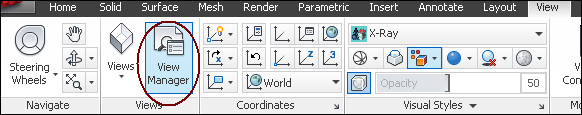
The VIEW command (alias V) creates and manages saved views. On the ribbon, we can also access this command on the View panel inside the View tab:
The command shows the View Manager box with three areas:
- Views: The area on the left shows the available views that are divided by Model Views, Layout Views, and Preset Views. Preset Views includes the predefined orthographic and isometric views. After selecting a view, its properties are shown in the central area.
- View: The central area displays the properties of the selected view on the left.
- Buttons: The buttons on the right allow for activating a view, creating a new view, updating layers associated to a view, editing its boundaries, and deleting a view.

To create a view, we click on the New option. The New View/Shot Properties box is displayed. The most important elements are:
- View name: The name that identifies the view.
- View category: If there are too many views, these can be grouped in categories, for instance, exterior or interior views. We may maintain the default category <None>.
- View type: We can choose a Still view, a Cinematic view, or a Recorded Walk view. Normally we want to save a Still view.
- View Properties: There are three areas in this tab: The Boundary area specifies if the saved view is exactly the current display, or we may, by clicking the button, define a new window. The Settings area allows saving the layers with the view, coordinate system, live section (if any), and visual style are saved. We can also associate and configure a background to the view.
Associating the layers' properties to the saved view is very useful. By restoring a view, we will get the same layers' properties, such as frozen or thawed layers, when the view was created. The Update Layers button allows for assigning the current layer's properties to the selected view. The Edit Boundaries button allows for zooming in or out of the selected view. It displays an expanded drawing area with the current view having the window background.
In the real world, we have a perspective projection. Objects farthest look smaller and parallel lines or edges look concurrent. When working in 3D models, it is easier to work with parallel projection, but for getting realistic final results we must turn perspective on:

To change between a parallel view and a perspective view, we can use the PERSPECTIVE variable: 1 to activate the perspective view and 0 to activate the parallel view. We can also use the Parallel and Perspective options on the shortcut menu over the view cube or the second viewport control.
All 3D programs have the simulation of cameras, and AutoCAD is no exception. Cameras are very handy because they simulate a real camera with position, target, and lens length. Cameras can be moved and we can populate a 3D model with cameras. At any time we can activate a particular camera view.
The CAMERA command (alias CAM) creates cameras. It prompts for the camera position and the target position, and displays a set of options. We press the Enter key; these options, if needed, can be changed later. Each camera is represented in the model by a wireframe blue object with a camera aspect, called camera glyph. The camera and target positions define the viewing direction. Cameras always have perspective projection. Camera views are always added to the Model Views group.

When we select a camera, besides displaying its cone, a preview window is also displayed, allowing for a better control of the camera view. Options are available for choosing the visual style and checking if this preview window is displayed upon camera selection.
We can modify cameras in two ways:
- Using the
PROPERTIEScommand, which is an excellent command. It allows for changing all objects' parameters and is also suitable for changing the camera's properties. We must activate this command's palette before selecting the camera. We can control the camera's name (Name), the camera's position coordinates (Camera X, Camera Y, and Camera Z), the target's position coordinates (Target X, Target Y, and Target Z), the camera's magnification or zoom (Lens length (mm) and Field of view), the camera's rotation around the viewing direction (Roll angle), and check if the camera representation object is plotted. Cameras can have visual clipping planes turned on and we can control the distances from the target position to the front clipping and back clipping planes (Front plane and Back plane).
- Using grips is another way to modify the cameras. When we select the camera, a cone with grips is displayed and we can activate the grips to change the besides positions of the camera and target, pan the camera, and change the lens length.
To activate a camera view, as all cameras are added to Model Views, we can use any restore view available, such as the VIEW command, the second viewport control, the View toolbar, or the ribbon. Another way is to use the camera's shortcut menu and select Set Camera View.
Note
The best way to create and control a camera is to specify the camera's position and the target on the Top view, and then, use the PROPERTIES command to give a name, control the camera's height and the target's height (for instance, to simulate the height of someone looking at the model), and adjust the lens length.
With the model used in Exercise 2.1, but with a conceptual visual style, we are going to create and apply views and cameras.
- Open the file
A3D_02_02.DWG. - Hide the top slab object. Select it and, on the shortcut menu, choose Isolate/Hide Objects.
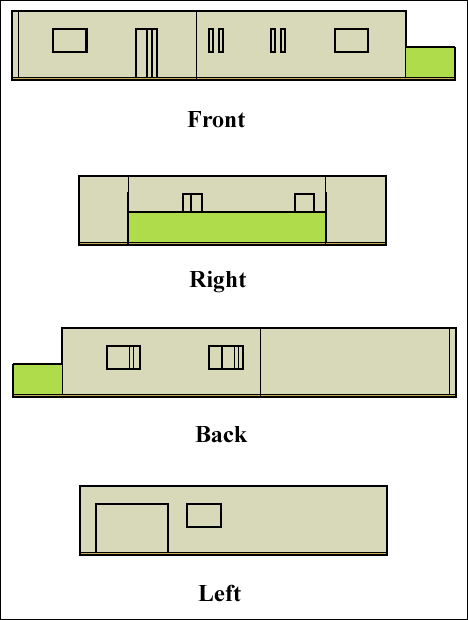
- Using the view cube, select the Front view. Then select the Right view, the Back view, and the Left view. Each time we select an orthographic view, the view direction rotates to display the chosen view.
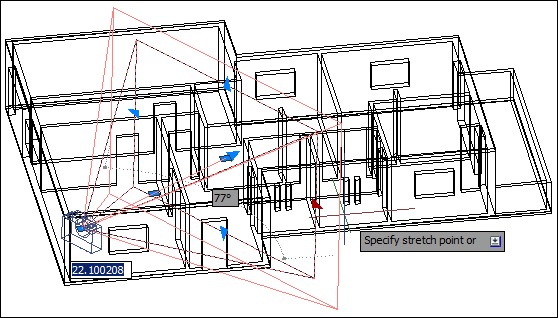
- We want a view that corresponds to a small rotation of the Top view, which when related to the model, will be positioned on the negative X and Y axis and the positive Z axis. Apply the
VPOINTcommand and specify the value -1,-2,1.5. The view rotates, so we have a nice view.
- Save this view. Apply the
VIEWcommand (aliasV) and press the New button. In the New View / Shot Properties box, name the values -1_-2_1.5 as name (view names don't accept commas, semicolons, or spaces). Don't change the remaining parameters. Press the OK button twice to end the command. - Select the perspective view. Place the cursor over the view cube, and with the shortcut menu, select Perspective. The background colors change to reflect the floor, sky, and the horizon line. Orbit the model to perceive these elements. These colors can be configured with the
OPTIONScommand (aliasOP), the Display tab, and the Colors button.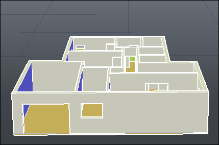
- Undo the commands until you come back to the parallel view.
- With the
PLANcommand, change to the Top view for the current UCS (actually the world coordinate system). A Zoom Extents option is automatically processed. - Apply the
CAMERAcommand (aliasCAM) to create a camera placed in the lower-left room and target the corridor. Press the Enter key to end the command. - Display the Properties palette (alias CTRL + 1). Select the camera. The Camera Preview window is displayed and the Properties palette reflects the camera's parameters. Change the following parameters: Name to
Living room, Camera Z to1.8, and Target Z to1.7. - On the Camera Preview window, change the visual style to Realistic. The preview is not famous, so we need to open the field of view. On the Properties palette, change Lens length (mm) to
18. Now, it is possible to see almost the entire living room.
- To activate the camera view, with the camera selected, on the shortcut menu specify Set Camera View.
- Press the Esc key to end the selection and save the model with the name
A3D_02_02final.DWG.