
In the previous pages, we already have seen some visual styles applied. Visual styles, introduced in Version 2007, specify the representation of the 3D model on each viewport, such as controlling edges, shading or wireframing, lighting, materials, and background.
AutoCAD comes with several visual styles already defined that cannot be eliminated and are available for all drawings. Since Version 2011, there are ten visual styles available. Previous versions have only five.
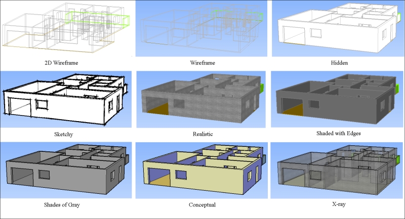
- 2D wireframe: This visual style only displays edges and is the only one that doesn't accept the perspective mode or background
- Wireframe: This visual style displays edges but accepts perspective mode and background
- Hidden: This visual style only displays visible edges, giving the feeling of opaque faces (hidden edges not visible)
- Sketchy: In this visual style, visible edges are displayed as if they were sketched by hand
- Realistic: In this visual style, faces are displayed with a smooth shade and with materials, if applied
- Shaded: In this visual style, faces are displayed with a smooth shade and without materials
- Shaded with Edges: This visual style is the same as shaded, but with visible edges highlighted
- Shades of Gray: This visual style is the same as shaded, but all colors are converted to grayscale
- Conceptual: In this visual style, faces are displayed with smooth shading, but with cool and warm colors, giving an artistic feeling
- X-ray: In this visual style, objects are displayed with some transparency
The
VSCURRENT command (alias VS) specifies the visual style for the current viewport. It works from the command line, which means that it is the quickest way for setting a predefined visual style. For instance, to set the Realistic style, we press the sequence VS and press the Enter key, and then R followed by the Enter key. To set the 2D Wireframe style, we press VS and the
Enter key, and then 2, followed by the Enter key.
Other possible ways to choose another visual style are the third viewport control (since Version 2012),the Visual Styles panel in the View tab on the ribbon, the Visual Styles toolbar, or the 3DORBIT command shortcut menu.
Normally, the ten
visual styles that come with AutoCAD are enough, but we may create others. The VISUALSTYLES command (alias VSM) displays a palette for creating and modifying visual styles.
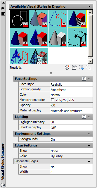
Below the Available Visual Styles in Drawing area are buttons to create a new visual style, to apply the selected visual style, to export the selected visual style to the TOOL PALETTES command palette, thus making it available to other drawings, and to delete the selected visual style. The shortcut menu over one of the slots also has options to apply it to all viewports, edit the description, copy and paste, modify the sample's size, and reset to the default parameters.
Visual styles' parameters are divided into:
- Face Settings: This parameter controls the face style (Realistic, Gooch, or None), lighting quality, color, opacity, and the material's display
- Lighting: This parameter controls the highlight intensity and the shadow's display
- Environmental Settings: This parameter controls the background
- Edge Settings: This parameter controls if the edges are displayed and how they are displayed, their color, and their sketchy effect
Better than an exhaustive description of all parameters is to apply a practical example. Besides the specified values, we may play around with options and values.
- Open the file
A3D_02_03.DWG. The visual style of this model is Realistic, with the materials and shadows options turned on.
- Apply the
VSMalias to call Visual Styles Manager. We are going to create a new visual style, without materials and shadows, and that is partially transparent and yellow. - Click on the Create New Visual Style button (the first one) and name it
My Yellow X-Ray. - Click on the second button to apply this visual style to the viewport so that any changes are immediately displayed.
- In the Face Settings option, click the small button named Opacity to turn it on. In Color specify Tint, and on Tint Color choose a yellow color. Don't change the value of Opacity (it should be 60), and Material display should already be turned off.
- In the Lighting option, click on the small button named Highlight intensity and specify 40. Shadow display should be off.
- Inside the Edge Settings option, specify Show as Isolines, Number of lines as 0, Color as Blue, and Always on top as Yes. And inside Occluded Edges, specify Show as No, and do the same with Intersection Edges and Silhouette Edges. In Edge Modifiers, the small buttons allow for the small lines' extension and sketchy mode (Jitter), but don't modify these.

- Click on the third button, Export the Selected Visual Style to the Tool Palette, and this visual style is placed on the default TOOL PALETTES. The correct way should be to first open TOOL PALETTES (Ctrl + 3), specify the Visual Styles palette, and then use the button.
- Save the model with the name
A3D_02_03final.DWG.