
Since for ever, documentation is a key part of 3D modeling. AutoCAD has several commands for creating projection, views, and sections from the model.
There are two commands for obtaining sections, the first one being more flexible and allowing the analyzation of 3D models.
The
SECTIONPLANE command (alias SPLANE) allows you to specify visual section cuts, composed of one or more planes. The command can be accessed on the ribbon, Home tab, Section panel, or on the Draw/Modeling menu bar. It can section solids, surfaces, and meshes.
The command prompts for the selection of a face or by specifying a point that defines the beginning of the section plane:
Command: SECTIONPLANE
Select face or any point to locate section line or [Draw section/Orthographic]: Face selection
After selecting the face, a plane is placed coincident with that face. This new object is called a section object, it will include all models and can then be activated and moved. If we specify a point not on any face, a second point is requested and a vertical plane is created that passes through both the points. We may have several planes defined, but only one can be activated.
Options for this command are:
- Draw section: We draw a section object composed of more than one plane. A sequence of points is requested and then, a point that defines the direction of the section view is drawn.
- Orthographic: We create an orthographic section plane, according to the active coordinate system. This option only prompts for the orthographic plane.
If we select a section plane and apply the shortcut menu, the access to several functions and related commands is provided:
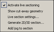
The functions and commands are listed as follows:
- Activate live sectioning: This applies the
LIVESECTIONcommand that activates or deactivates the section plane - Show cut-away geometry: With this option checked, the cut geometry is represented with properties specified by settings; by default, red and transparent
- Live section settings: This applies the
SECTIONPLANESETTINGScommand. This command controls the section parameters - Generate 2D/3D section: This applies the
SECTIONPLANETOBLOCKcommand. This command displays a dialog box - Add jog to section: This applies the
SECTIONPLANEJOGcommand that allows adding vertices to the section line, thus creating a new plane with a 90 degree angle
One of the major utilities of this command is the section generation. This section is generated as an anonymous block that can be placed, for instance, on a layout. By applying Generate 2D/3D section on the section plane shortcut menu (or the SECTIONPLANETOBLOCK command), a dialog box is displayed, with the following options:
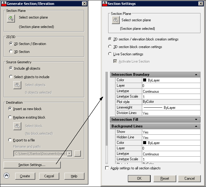
In Section Plane, we can select the plane. In 2D/3D, we can choose between creating a planar 2D section or a 3D section. In Source Geometry, we can specify if the whole model is used for the section block generation, or if any specific objects are selected using the button below it. Destination specifies if the section is inserted in the drawing as a new block; it replaces an existing block, or is exported as a DWG or DXF file.
The button Section Settings calls the SECTIONPLANESETTINGS command, allowing you to specify all section parameters. These are divided by 2D section / elevation block creation, 3D section block, and Live Section. The 2D section contains all the following five panels:
- Intersection Boundary: This panel contains all parameters, such as color, layer, and lineweight, for lines corresponding to the intersection of geometry with the section plane, cut line
- Intersection Fill: This panel defines the hatch or fill corresponding to material cut by the section plane
- Background Lines: This panel defines all parameters for background lines; this panel is not available for Live Section
- Cut-away Geometry: This panel contains the parameters for cut-away geometry; by default, this is not shown
- Curve Tangency Lines: This panel controls the appearance of edges shared by curved and planar continuous faces, but this panel is only available for 2D sections
If we choose to insert a block, we press the Create button. A block is created and the command prompts for the insertion point, X scale factor, Y scale factor, and rotation. The block is inserted in the current UCS.

The SECTION command (alias SEC) is an old command for creating sections from 3D geometry, but very easy to apply. The result is a region or a curve for each cut object. The command prompts for the selection of 3D objects (can be solids, surfaces, or meshes):
Command: SECTION
Select objects: Selection
By default, the section plane is defined by three points:
Specify first point on Section plane by [Object/Zaxis/View/XY/YZ/ZX/3points] <3points>: Point
Specify second point on plane: Point
Specify third point on plane: Point
- Object: The section plane is defined by a planar object to be selected, such as a circle, an ellipse, an arc, a 2D spline, or a 2D polyline
- Zaxis: The section plane is defined by a point on that plane and a second point that specifies the normal to the plane
- View: The section plane is parallel to the current view that passes through a point to be specified
- XY/YZ/ZX: The section plane is parallel to the XY, YZ, or ZX plane that passes through a point to be specified
With the same model, we are going to create some sections:
- Open the drawing
A3D_09_2.DWG. - The sections should be on a proper layer, so create a SECTIONS layer and make it the current layer.
- With the
SECTIONcommand create a section parallel to the ZX plane that passes through the middle of the assembly. The command creates four regions overlapping the geometry. - Move aside the four regions that are created.
- Again with the
SECTIONcommand, create a section parallel to XY plane that passes through the center of the bolt, and move the four new regions to the side:
- Create a new layer called SECTIONPLANES and make it current. Freeze the SECTIONS layer.
- With the
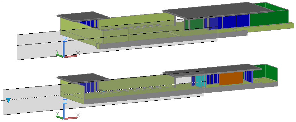
SECTIONPLANEcommand we want a section coincident with the ZX plane, for instance, applying the Orthographic option and, then the Front option. The plane cuts the assembly in half. - With the shortcut menu, activate Show cut-away geometry. The first half of the assembly is represented in red and transparent.
- Let's now create a block that represents this section. Again, with the shortcut menu, choose Generate 2D/3D section. At the Generate Section/Elevation box, confirm 2D Section/Elevation, Include all objects, and Insert as new block. We press the Section Settings button and modify the following: Face Hatch as User-defined; Angle as 45; Hatch Spacing as 3; Color as Blue; Background Lines Hidden Line as No; Curve Tangency Lines Show as No. Press OK and Create. The block is displayed, on the XY plane. Specify an insertion point, for instance, X scale
1, Y scale1, and rotation0. - Save the drawing with the name
A3D_09_2final.DWG:
While the SECTIONPLANE command creates sections, the next command creates projections, or flattened views.
The FLATSHOT command (no alias) creates a 2D representation of all 3D objects in the drawing by projecting all edges onto a plane perpendicular to the viewing direction. It can be applied to solids, surfaces, meshes, and regions.
First, we must set the viewing direction. Upon calling the command, a dialog box is displayed, including three areas and an option:
- Destination: This area is similar to the same area as the
SECTIONPLANEBLOCKcommand and specifies whether the view is inserted in the drawing as a new block, it replaces an existing block, or is exported as a DWG or DXF file - Foreground lines: This area allows you to specify the color and linetype for visible edges in the projected view
- Obscured lines: This area allows you to specify whether hidden edges are represented in the projected view and, in affirmative case, their colors and line-types
- Include tangential edges: When this option is checked, it draws profile or silhouette lines for curved surfaces or faces

As before, if we choose to insert a block, when pressing the Create button, a block is created. The command prompts for insertion point, X scale factor, Y scale factor, and rotation. The block is inserted in the current UCS.
We continue the model from Exercise 9.2, now creating some flattened and projected views.
- Open the drawing
A3D_09_3.DWG. - Projected views should be on a proper layer, so create and activate a layer called 2DVIEWS.
- With the ViewCube tool, the Front view is specified.
- Applying the
FLATSHOTcommand, on the dialog box confirm Insert as new block, uncheck Obscured Lines Show, and check Include tangential edges. Upon pressing Create, specify an insertion point not far from the model for the new block and confirm scales and rotation. - Specify the Top view and repeat the
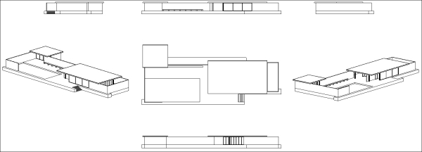
FLATSHOTcommand with the same parameters. Place the new block on the same plane and near the previous block. - Repeat the command with the Left and Right views and a view from the third quadrant. Arranging the blocks, you should have a display similar to the next diagram (first angle projection, also known as European projection).
- Save the drawing with the name
A3D_09_3final.DWG: