
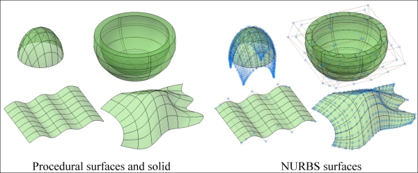
NURBS surfaces are based on splines and are mainly used for free-form surfaces such as those used in the automotive industry. There are two processes for creating NURBS surfaces and several commands to edit them, which are presented next.
We can create NURBS surfaces by previously specifying a value 1 for the SURFACEMODELINGMODE system variable and applying surface creation commands, or by converting existing objects with the CONVTONURBS command.
When creating surfaces, the SURFACEMODELINGMODE variable controls if NURBS or procedural surfaces are created:
This variable is not saved and by default is set to 0.
Basically, there are two ways to edit NURBS surfaces: applying the 3DEDITBAR command and editing control vertices. These can be shown, dragged to new positions, thus modeling the surface, and vertices can be added or removed. A last command allows rebuilding the surface.
The 3DEDITBAR (no alias) command allows modifying NURBS surfaces and splines by moving points and changing direction and magnitude at specific points. Besides the command line, the command is available only on the ribbon, Surface tab. The command starts by prompting the selection of a NURBS surface or spline:
Command: 3DEDITBAR
Select a NURBS surface or curve to edit: Selection
Then, it prompts for a point on the surface, displaying two perpendicular red lines:
Select point on NURBS surface. Point
The 3DMOVE gizmo is displayed with three grips, which is explained next. Pressing Enter ends the command. The Base point option allows selecting a different point on the surface and the Displacement option allows defining a new base point by projecting coordinates on the surface:
Select a grip on the edit bar or [Base point/Displacement/Undo/eXit]<exit>: Selection or Enter
There are three grips associated to the gizmo that allow shaping the surface:
- Square grip: This grip moves the surface or aligns its tangent (accessed by the right-click button menu)
- Triangle grip: This grip allows choosing to move or to align the tangent
- Tangent arrow grip: This grip modifies the tangent magnitude

The CVSHOW command (no alias)
allows displaying the control points for selected NURBS surfaces or splines. It just prompts for the selection:
Command: CVSHOW
Select NURBS surfaces or curves to display control Vertices: Selection
The CVHIDE command (no alias) turns off the control point's visualization for all NURBS surfaces and splines. It prompts nothing.
The CVADD command (no alias) allows adding control points in the U or V direction, or directly on the surface or spline. The command prompts for the selection of a NURBS surface or spline:
Command: CVADD
Select a NURBS surface or curve to add control vertices: Selection
By default, the specified point adds a row of control vertices in U direction and the command ends. The Direction option allows changing to the other direction. The insert Knots option allows inserting knots on the surface, instead of control vertices:
Adding control vertices in U direction
Select point on surface or [insert Knots/Direction]: Direction
Adding control vertices in V direction
Select point on surface or [insert Knots/Direction]: Point

The CVREMOVE command (no alias) allows you to remove control vertices. The command prompts for the selection of a NURBS surface or spline:
Command: CVREMOVE
Select a NURBS surface or curve to remove control vertices: Selection
The existing rows of control vertices are displayed, in order to select the one that will be removed. The Direction option allows changing to the other direction:
Removing control vertices in U direction
Select point on surface or [Direction]: Point
The CVREBUILD command (no alias) allows rebuilding NURBS surfaces and splines. When a NURBS surface or curve has too many vertices or when we need to increase or decrease the degree, this is the command to apply. The command prompts for the selection of a surface or spline and displays a dialog box:
Command: CVREBUILD
Select a NURBS surface or curve to rebuild: Selection

This box has the following options:
- Control Vertices Count: In this option, we control the number of control vertices in U and V directions.
- Degree: In this option, we control the surface degree in U and V directions.
- Options: Deleting original geometry does not maintain the original surface when sorting the command. If the original surface is trimmed (Retrim previously trimmed surface), this option maintains the trim on the new surface.
We are going to create a NURBS surface to simulate a circular terrain:
- Start a new drawing.
- Create a circle with
40units radius. - A layer, called
Surface, with color at choice, should be created and activated. - With the
PLANESURFcommand and the Object option, a planar round surface is created. - Applying the
CONVTONURBScommand, this surface is transformed into a NURBS surface. - To display control points, apply the
CVSHOWcommand and select the surface. There are only four control points at the corners of the bounding rectangle. - The
CVREBUILDcommand allows you to increase control points and degree. Define six control vertices in each direction.
- Now it is easy to model the surface. With Polar or Ortho turned on, move control points up or down. To pick control points, it is better to use the 2D wireframe visual style.
- Save the drawing with the name
A3D_12_03final.DWG.