
Frequently, we need to measure distances and volumes and obtain point coordinates. In 3D, it is also important to detect interferences and to obtain geometric properties of solids.
Topics covered in this chapter:
- How to obtain point coordinates
- How to measure distances and angles
- How to detect interferences
- How to create solids from interferences
- How to measure volumes
- How to obtain geometric properties
Measuring and obtaining point coordinates is a constant part of our 3D work. The commands present here can be found on the Inquiry toolbar, and on the menu bar by going to Tools | Inquiry. Both 3D Basics and 3D Modeling workspaces don't have these commands, unlike the Drafting & Annotation workspace.

One of the most important things in AutoCAD is to know precise point coordinates. For that, we apply the next command.
The ID command allows us to obtain the X, Y, and Z coordinates of points related to the current User Coordinate System (UCS). This command can be used transparently, that is, in the middle of another command, if we prefix it with a ' (single quotation) mark. The command only prompts for a point:
Command: ID
Specify point: Point
The command writes the X, Y, and Z coordinates, related to the current UCS, on the command line:
X = 28.9427 Y = 15.0000 Z = 10.0000
To measure distances, perimeters, and angles, we can apply the following commands.
The DIST command (alias DI) is, for sure, one of the most commonly used commands, allowing us to measure distances,
perimeters, and angles. By default, the command prompts for two points:
Command: DIST
Specify first point: Point
Specify second point or [Multiple points]: Point
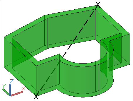
The command returns the real distance (in 3D), the projected angle onto the XY plane, the angle from the XY plane, and all increments along the three directions:
Distance = 21.4783,  Angle in XY Plane = 29,  Angle from XY Plane = 16
Delta X = 17.9994,  Delta Y = 10.0666,   Delta Z = 6.0000
The result can be seen in the following screenshot:
Since Version 2010, this command has one new option, which is as follows:
- Multiple points: This option allows you to specify multiple points, and returns the perimeter. We can specify a sequence of points and the command sums up the partial distances. Additional options allow the inclusion of arcs and the respective options, closing the perimeter, specifying a length, undoing the last point, and obtaining the total.
The MEASUREGEOM command (alias MEA) allows us to obtain several measures, including distances, radius, angles, areas, and volumes. The command displays a set of options, shows the results on the command line, and repeats until we press the Esc key.
Command: MEASUREGEOM
Enter an option [Distance/Radius/Angle/ARea/Volume] <Distance>: Option
This command has the following options:
- Distance: This option works exactly the same way as the
DISTcommand, which was presented before. - Radius: This option prompts for the selection of an arc, a circle, or a circular edge and displays its radius and diameter.
- Angle: This option simulates the
DIMANGULARcommand, that is, it prompts for the selection of an arc, circle, line, or vertex and returns the angle. We can also select straight or circular edges. - ARea: This option works exactly the same way as the
AREAcommand. - Volume: This option allows us to obtain volumes, similar to the ARea option. Volumes can be specified by a sequence of points (first the base perimeter and then the height) and an object selection. Additional options allow adding or subtracting volumes.
We are going to obtain some information about a 3D model.
- We open the drawing
A3D_08_01.DWG. - Applying the
IDcommand, we obtain the coordinates of points A, B, C, and D: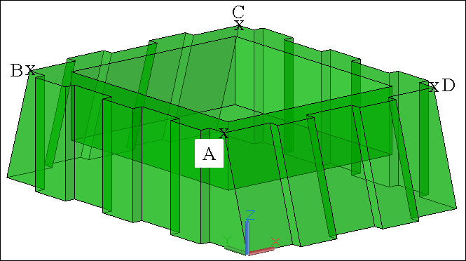
The coordinates of points A, B, C, and D are as follows:
X = 0.0000     Y = 3.0573     Z = 10.0000
X = 0.0000     Y = 28.9427     Z = 10.0000
X = 23.0000     Y = 28.9427     Z = 10.0000
X = 23.0000     Y = 3.0573     Z = 10.0000
- Applying the
DISTcommand and the Multiple points option, we obtain the perimeter of the top exterior border:Distance = 118.1363 - Applying the
MEASUREGEOMcommand and the Angle option, we obtain the angle of the inclined faces:Angle = 73° - Again, with the last command and the ARea/Object option, we obtain the surface area of the solid:
Area = 3142.9782 - And without leaving the command, now with the Volume/Object option, we obtain the solid volume:
Volume = 4808.5069 - As there were no modifications, we don't need to save the drawing.