
As in 2D, AutoCAD has also some variables responsible for the creation or visualization of 3D objects:
ISOLINES: This variable controls the number of lines used to represent curved faces of solids with the wireframe visual style. These isolines should not be confused with edges. By default, its initial value is4and it is saved with the drawing.DISPSILH: This variable controls the display of silhouette edges of solids when applying a wireframe visual style. It is saved with the drawing and accepts two values,0(the silhouette is not displayed; this is the default) and1(silhouettes are displayed).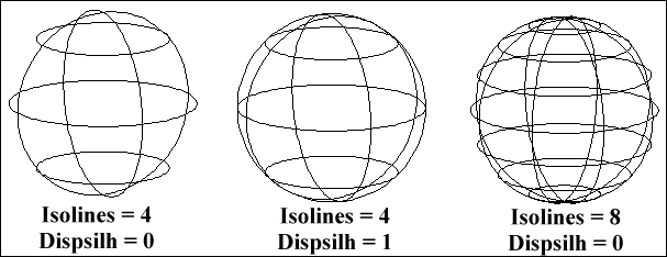
FACETRES: This variable controls the amount of faceted faces used to represent shaded or rendered objects. All shaded or rendered views are calculated by faceting all curved surfaces and faces. By default, its initial value is0.5and it is saved with the drawing. Its value can go from0.01to10; a reasonable value is2or3.
DELOBJ: This variable controls if linear objects used to create solids or surfaces are deleted. By default, its initial value is3and it is saved in the registry. It accepts the following values:0(all geometry is maintained),1(deletes only section objects),2(deletes sections, paths, and guide objects), and3(same as2, but only if a solid is created). It can also accept-1,-2, and-3with similar behavior as positive values, but requests confirmation for deletion.SURFACEASSOCIATIVITY: This variable controls if surfaces maintain an association to original linear objects. By default, its initial value is1and it is saved with the drawing. It accepts two values,0(association is not maintained) and1(association is maintained). With a value of1, theDELOBJvariable is ignored when creating surfaces.SURFUandSURFV: These variables control the density of the surface isolines in the first and second directions. By default, their initial value is6and they are saved with the drawing.LOFTPARAM: This variable controls the shape of lofted objects. By default, its value is7. It is saved with the drawing and is defined by the following values:1(sections do not twist),2(aligns directions in each section),4(simplifies solids and surfaces), and8(closes the lofted object between the first and last sections).LOFTNORMALS: This variable controls the shape of the lofted object in terms of transition between sections. By default, its initial value is1and it is saved with the drawing. It accepts the following values:0(ruled),1(smooth fit),2(normal to the first section),3(normal to the last section),4(normal to the first and last sections),5(normal to all sections), and6(apply the draft angle and magnitude).LOFTANG1andLOFTANG2: These variables define the tangency angles at the first and last sections of the lofted object. By default, their initial values are9and0and they are saved with the drawing.LOFTMAG1andLOFTMAG2: These variables define the magnitude (intensity) of draft angles at the first and last sections of the lofted object. By default, their initial values are0and they are saved with the drawing.
..................Content has been hidden....................
You can't read the all page of ebook, please click here login for view all page.