
An important part of any 3D project is combining solids and editing solids and surfaces. Among other useful commands, we can union, subtract, intersect, and cut 3D objects, as well as applying fillets and chamfers to objects edges. In this chapter, we present all the main commands for editing solids and surfaces.
The topics covered in this chapter are as follows:
- Applying unions, subtractions, and intersections
- Cutting and dividing 3D objects
- Filleting and chamfering edges
- Editing faces, edges, and volumes of solids
- Creating copies and offsets from edges
- Projecting objects onto 3D objects
- Adding thickness to surfaces
Until now, we dealt with the creation of 3D objects. Now, let's see how to combine and modify them.
Three basic operations to combine objects are unions, subtractions, and intersections. These are called Boolean operations and can be applied to solids, surfaces, and regions.
The commands to perform unions, subtractions, and intersections can be found on the ribbon, Home | Solid Editing panel, on the Modeling toolbar, and on the Menu bar, Modify | Solid Editing:

The UNION command (alias UNI) joins two or more objects into one. The command can be applied to solids, surfaces, and regions, but it only joins objects of the same type, that is, it can't join solids with surfaces or regions. It only prompts for the selection of objects to join and returns only one object:
Command: UNION
Select objects: Selection
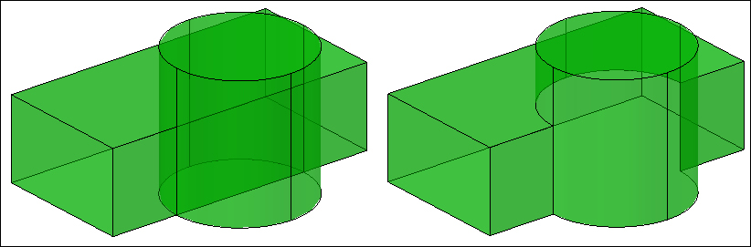
Duplicated volumes or areas are removed.
The command can be applied to solids that do not share a common volume or regions that do not share a common area. In this case, we get one object despite having separated volumes or areas. As it is not possible to join 3D meshes, upon its selection the command prompts for its conversion to solid or surface.
Note
The application of UNION to surfaces is of minimum interest. In case we need to perform operations on surfaces, the surface commands presented in Chapter 12, Meshes and surfaces are more useful.
The SUBTRACT command (alias SU) allows you to subtract the volume of other objects to a first set of objects. The command can be applied to solids, surfaces, and regions, but doesn't work with objects of different types. The command returns a single object. It starts by prompting the first set of objects:
Command: SUBTRACT
Select solids, surfaces, and regions to subtract from ..
Select objects: Selection
Then it prompts for the second set of objects. The volume of this set will be removed from the first set:
Select solids, surfaces, and regions to subtract ..
Select objects: Selection
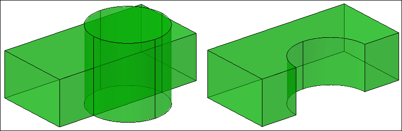
Since Version 2010, this command allows subtracting coplanar surfaces and also subtracting solids to a surface.

Applying this command to subtract non-coplanar surfaces results in erasing the second set of surfaces and nothing happens to the first set.
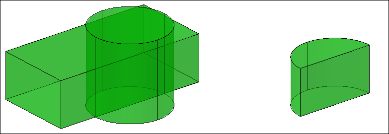
The INTERSECT command (alias IN) allows the intersection of objects. Applying to solids returns the common volume, applying to regions and coplanar surfaces returns the common area, and applying to intersecting non planar surfaces returns the intersecting spline. The command just prompts for the selection of objects and returns only one object:
Command: INTERSECT
Select objects: Selection
Under some conditions, we may be able to modify original components of composite objects.
If composite objects, obtained by unions, subtractions, or intersections, have recorded history, that is, kept track of original components, we may edit them by modifying these components.
To record history and have access to original components, we may select the solids to combine and set History to Record on the PROPERTIES palette. By default, all solids don't record history. If we want all solids to record history upon their creation, we have to change the SOLIDHIST variable to 1 (by default, it is 0).
To select a component, we press the Ctrl key and click on a surface or edge caused by the component we want to modify. Then we can use grips, the PROPERTIES palette, and some editing commands, such as MOVE or 3DMOVE, to edit the component. The composite object updates immediately.

The SHOWHIST variable specifies if component objects are displayed even if we don't select them with the Ctrl key. With value 2, component objects are always displayed; with value 1, it depends on individual properties; with value 0, they are never displayed.
The BREP command (no alias)
allows removing history records and edition through grips or the PROPERTIES palette for the objects to be selected. It only prompts for the selection of composite solids, solid primitives, or solids obtained from linear objects.
All selected solids become generic 3D solids.
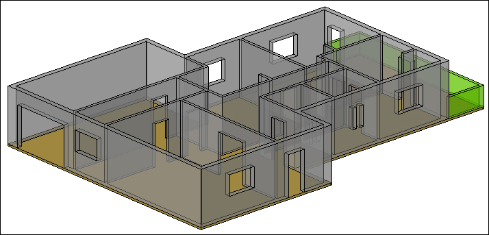
We are completing the house initiated in Chapter 4, Creating Solids and Surfaces from 2D.
- Open the drawing
A3D_07_01.DWG. This drawing contains the solids of the one-floor house created from a 2D drawing. - A good view to select all objects is the Front view, accessed by the view cube or another process.
- First, unite all walls and the solids above doors. Apply the
UNIONcommand, selecting all18solids on the3D-WALLSby opening a rectangle from right to left (crossing) above windows and below the upper slab.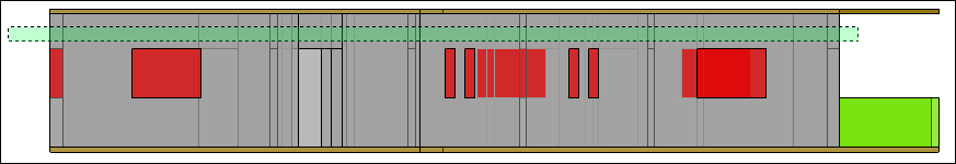
- We apply
SUBTRACT, select the object walls, press Enter, select all windows from left to right, and include all the windows completely. - Orbiting and eventually hiding the upper slab, we can verify the model correction.
- Save the drawing with the name
A3D_07_01FINAL.DWG.
We are going to continue the cathedral by applying some unions and subtractions.
- Open the drawing
A3D_07_02.DWG. This drawing contains the primitive solids created in Exercise 5.4 of Chapter 5, 3D Primitives and Conversions. - Apply the
UNIONcommand and select all the boxes, the two pyramids, the rear cylinder and cone, and the torus. All these objects become a single one:
- To create the buttresses, apply the
SUBTRACTcommand, select all the six larger wedges, press the Enter key, and select all six smaller wedges. The result is a single object for all buttresses, but we don't need these as separate objects:
- We Save the drawing with the name
A3D_07_02FINAL.DWG. Later we will cut the summit and make a hollow in the big block.