This recipe covers 2D drawing in OpenGL ES 1.x by example.
In order to draw 2D objects, we'll also describe the OpenGL rendering display through GLSurfaceView, adding colors to them, and transformation.
Readers are recommended to read the introduction of this chapter, which is essential to understand some of the content in this recipe.
The following steps create our sample Android NDK project:
- Create an Android application named
TwoDG1. Set the package name ascookbook.chapter4.gl1x. Please refer to the Loading native libraries and registering native methods recipe in Chapter 2, Java Native Interface, if you want more detailed instructions. - Right-click on the
TwoDG1project in Eclipse, select Android Tools | Add Native Support. - Add the following three Java files under the
cookbook.chapter4.gl1xpackage:MyActivity.java: It creates the activity of this project:import android.opengl.GLSurfaceView; …… public class MyActivity extends Activity { private GLSurfaceView mGLView; @Override public void onCreate(Bundle savedInstanceState) { super.onCreate(savedInstanceState); mGLView = new MySurfaceView(this); setContentView(mGLView); } }MySurfaceView.java: It extendsGLSurfaceView, which provides a dedicated surface for displaying OpenGL rendering:public class MySurfaceView extends GLSurfaceView { private MyRenderer mRenderer; public MySurfaceView(Context context) { super(context); mRenderer = new MyRenderer(); this.setRenderer(mRenderer); this.setRenderMode(GLSurfaceView.RENDERMODE_WHEN_DIRTY); } }MyRenderer.java: It implementsRendererand calls the native methods:public class MyRenderer implements GLSurfaceView.Renderer{ @Override public void onSurfaceCreated(GL10 gl, EGLConfig config) { naInitGL1x(); } @Override public void onDrawFrame(GL10 gl) { naDrawGraphics(); } @Override public void onSurfaceChanged(GL10 gl, int width, int height) { naSurfaceChanged(width, height); } ...... }
- Add the
TwoDG1.cpp,Triangle.cpp,Square.cpp,Triangle.h, andSquare.hfiles under thejnifolder. Please refer to the downloaded project for the complete content. Here, we only list some important parts of the code:TwoDG1.cpp: It consists of the code to set up the OpenGL ES 1.x environment and perform the transforms:void naInitGL1x(JNIEnv* env, jclass clazz) { glDisable(GL_DITHER); glHint(GL_PERSPECTIVE_CORRECTION_HINT, GL_FASTEST); glClearColor(0.0f, 0.0f, 0.0f, 1.0f); glShadeModel(GL_SMOOTH); } void naSurfaceChanged(JNIEnv* env, jclass clazz, int width, int height) { glViewport(0, 0, width, height); float ratio = (float) width / (float)height; glMatrixMode(GL_PROJECTION); glLoadIdentity(); glOrthof(-ratio, ratio, -1, 1, 0, 1); } void naDrawGraphics(JNIEnv* env, jclass clazz) { glClear(GL_COLOR_BUFFER_BIT); glMatrixMode(GL_MODELVIEW); glLoadIdentity(); glTranslatef(0.3f, 0.0f, 0.0f); //move to the right glScalef(0.2f, 0.2f, 0.2f); // Scale down mTriangle.draw(); glLoadIdentity(); glTranslatef(-0.3f, 0.0f, 0.0f); //move to the left glScalef(0.2f, 0.2f, 0.2f); // Scale down glRotatef(45.0, 0.0, 0.0, 1.0); //rotate mSquare.draw(); }Triangle.cpp: It draws a 2D triangle:void Triangle::draw() { glEnableClientState(GL_VERTEX_ARRAY); glVertexPointer(3, GL_FLOAT, 0, vertices); glColor4f(0.5f, 0.5f, 0.5f, 0.5f); //set the current color glDrawArrays(GL_TRIANGLES, 0, 9/3); glDisableClientState(GL_VERTEX_ARRAY); }Square.cpp: It draws a 2D square:void Square::draw() { glEnableClientState(GL_VERTEX_ARRAY); glEnableClientState(GL_COLOR_ARRAY); glVertexPointer(3, GL_FLOAT, 0, vertices); glColorPointer(4, GL_FLOAT, 0, colors); glDrawElements(GL_TRIANGLES, 6, GL_UNSIGNED_BYTE, indices); glDisableClientState(GL_VERTEX_ARRAY); glDisableClientState(GL_COLOR_ARRAY); } - Add the
Android.mkfile under thejnifolder with following content :LOCAL_PATH := $(call my-dir) include $(CLEAR_VARS) LOCAL_MODULE := TwoDG1 LOCAL_SRC_FILES := Triangle.cpp Square.cpp TwoDG1.cpp LOCAL_LDLIBS := -lGLESv1_CM -llog include $(BUILD_SHARED_LIBRARY)
- Build the Android NDK application and run it on an Android device. The following is a screenshot of the display:

This recipe demonstrates basic 2D drawing with OpenGL ES.
GLSurfaceView and GLSurfaceView.Renderer are the two foundational classes provided by Android SDK to display OpenGL ES graphics.
GLSurfaceView accepts a user defined Renderer object that
does the actual rendering. It is often extended to handle touch events, which is illustrated in the next recipe. It supports both on-demand and continuous rendering. In our sample code, we simply set the Renderer object and configure the rendering mode to on-demand.
GLSurfaceView.Renderer is the interface for renderer. Three methods need to be implemented with it:
onSurfaceCreated: It's called once when setting up the OpenGL ES environment.onSurfaceChanged: It's called if the geometry of the view changes; most common examples are device screen orientation changes.onDrawFrame: It's called at each redraw of the view.
In our sample project, MyRenderer.java is a simple wrapper, while the actual work is done in native C++ code.
Two methods are commonly used to draw objects in
OpenGL ES, including glDrawArrays and glDrawElements. We demonstrate the usage of these two methods in Triangle.cpp and Square.cpp respectively. Note that both the methods require GL_VERTEX_ARRAY to be enabled.
The first argument is the mode of drawing, which indicates the primitive to use. In our sample code, we used GL_TRIANGLES, which means we're actually drawing two triangles to form the square. Other valid values in Android NDK OpenGL ES include GL_POINTS, GL_LINES, GL_LINE_LOOP, GL_LINE_STRIP, GL_TRIANGLE_STRIP, and GL_TRIANGLE_FAN.
We also demonstrate two methods to add colors to the objects.
In Triangle.cpp, we set the current color by the glColor4f API call. In Square.cpp, we enable GL_COLOR_ARRAY, and define an array of color by using glColorPointer. The array of colors will be used by the glDrawElements (it's also OK to use glDrawArrays) API call.
The following diagram illustrates different transformation stages in OpenGL ES 1.0:
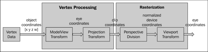
As illustrated in the diagram, vertex data are transformed before rasterization. The transforms are analogous to taking a photograph with a camera:
ModelView transform actually refers to two different transforms, namely Model Transform and View Transform. Model Transform refers to the process of converting all objects from its object space (also known as local space or model space) to a world space, which is shared among all objects. This transform is done through a series of scaling (glScalef), rotation (glRotatef) and translation (glTranslatef).
glScalef: It stretches, shrinks, or reflects an object. The x-, y- and z-axis values are multiplied by the corresponding x, y, and z scaling factor. In our sample code, we calledglScalef(0.2f, 0.2f, 0.2f)to scale down both the triangle and the square, so that they can fit into the screen.glRotatef: It rotates an object in a counter clockwise manner in the direction from the origin through specified point (x, y, z). The rotation angle is measured in degrees. In our sample code, we calledglRotatef(45.0, 0.0, 0.0, 1.0)to rotate the square about the z-axis by 45 degrees.glTranslatef: It moves an object by the given values along each axis. In our sample code, we calledglTranslatef(0.3f, 0.0f, 0.0f)to move the triangle to the right andglTranslatef(-0.3f, 0.0f, 0.0f)to move the square to the left, so that they won't overlap.
Model transform arranges the objects in a scene, while View transform changes the position of the viewing camera. To produce a specific image, we can either move the objects or change our camera position. Therefore, OpenGL ES internally performs the two transforms using a single matrix – the +
GL_MODELVIEW matrix.
Projection transform determines what can be seen (analogous to choosing camera lens and zoom factor) and how vertex data are projected onto the screen. OpenGL ES supports two modes of projection, namely perspective projection (glFrustum) and orthographic projection (glOrtho).
Perspective projection makes objects that are farther away smaller, which matches with a normal camera. On the other hand,
Orthographic projection is analogous to the telescope, which maps objects directly without affecting their size. OpenGL ES manipulates the transform through the GL_PROJECTION matrix. After a project transform, objects which are outside of the clipping volume are clipped out and not drawn in the final scene. In our sample project, we called
glOrthof(-ratio, ratio, -1, 1, 0, 10) to specify the viewing volume, where ratio refers to the width to height ratio of the screen.
After projection transform, perspective division is done by dividing the clip coordinates by the transformed w value of the input vertex. The values the for x-, y-, and z-axes will be normalized to the range between -1.0 to 1.0.
The final stage of the OpenGL ES transform pipeline is the viewport transform, which maps the normalized device coordinates to window coordinates (in pixels, with the origin at the upper-left corner). Note that a viewpoint also includes a z component, which is needed for situations, such as ordering of two overlapping OpenGL scenes, and can be set with the glDepthRange API call. Applications usually need to set viewport when the display size changes through the
glViewport API call. In our example, we set the viewport as the entire screen by calling glViewport(0, 0, width, height). This setting, together with the glOrthof call, will keep the objects in proportion after projection transform, as shown in the following diagram:

As shown in the diagram, the clipping volume is set to (-width/height, width/height, -1, 1, 0, 1). At perspective division, the vertex is divided by w. At viewpoint transform, both the x and y coordinates ranges are scaled up by w*height/2. Therefore, the objects will be in proportion as shown in the How to do it... section of this recipe. The left-had side of the following screenshot shows the output, if we set clipping volume by calling glOrthof(-1, 1, -1, 1, 0, 1), and the right one indicates what the graphics look like if viewport is set by calling glViewport(0, 0, width/2, height/5):
