
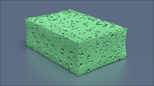
In this recipe we will create a polyurethane sponge material, the type that you can usually find in any kitchen:
- Start Blender and switch to the Cycles Render engine.
- If not already selected, select the default cube and in the Transform panel to the right of the 3D view, under Dimensions, digit these values: X 0.350, Y 0.235, and Z 0.116. Press Ctrl + A to apply the scale.
- Put the mouse in the 3D view and add a plane to the scene (Shift + A | Mesh | Plane). Go out of Edit Mode and in the Transform panel, Dimensions tab, write: X 20.000 and Y 20.000. Again press Ctrl + A to apply the scale. Move the plane down (G | Z | -0.05958 | Enter), to be the floor for the cube.
- Select the Lamp, in the Object Data window click on the Use Nodes button and change the type to a Sun. Set the Size to 0.500, the Color to pure white, and the Strength to 5.000. In the Transform panel write these values: Location X 3.44784, Y -1.15659, Z 14.12848; Rotation X 15°, Y 0°, Z 76°.
- Select the Camera and in the Object Data window, under the Lens tab, change the Focal Length to 60.000. In the Transform panel write these values: Location X 0.82385, Y -0.64613, Z 0.39382; Rotation X 68°, Y 0°, Z 51°.
- Go to the World window and click on the Use Nodes button under the Surface tab; click on the little square with a dot on the right side of the color slot: from the menu select Sky Texture. Set the Strength to 0.100.
- Go to the Render window and under the Sampling tab set the Clamp value to 1.00 and the Samples for Render and Preview to 50.
- Split the 3D view in two rows: change the upper one in a Node Editor window. Split the bottom view in two parts and change the left one into another 3D view. Put the mouse in the left 3D view and press 0 on the numpad to go in Camera view.
- Select the cube and, with the mouse in the Camera view, press Shift + S | Cursor to Selected to place the cursor on the pivot of the cube (in case it's elsewhere): add a Lattice to the scene (Shift + A | Lattice), press Tab to go out of Edit Mode and in the Transform panel, under Scale, write X 0.396, Y 0.264, and Z 0.129. Go to the Object Data window and in the Lattice slot set the U, V, and W values to 3.
- Reselect the cube and go in the Object Modifiers window; assign a Subdivision Surface modifier, switch the type of subdivision algorithm from Catmull-Clark to Simple, and set the Subdivisions to 2 both for View and Render.
- Assign a Bevel modifier and set the Width to 0.0010. Assign a Lattice modifier and in the Object slot select the Lattice name. Reselect the Lattice and press Tab to go in Edit Mode; select the Lattice vertexes as indicated in the following image:

- Scale a bit smaller the selected vertexes only on the X and Y axis (S | Shift + Z | .9 | Enter), then scale a bit smaller only the upper vertexes, and so on, to obtain the result of a shape similar to a kitchen sponge. When done, go out of Edit Mode (Tab).
- Reselect the cube and in the Object Tools panel, under Shading, select Smooth. With the mouse in the 3D view, press N and T to get rid of the Transform and Object Tools panels. Go to the Material window.
And now let's start with the creation of the material:
- As first thing, select the plane and click on New in the Material window under the Properties panel or in the Node Editor header. In the Material window switch the Diffuse BSDF node with a Mix Shader node: in the first Shader slot select a Diffuse BSDF node and in the second Shader slot a Glossy BSDF shader node. Set the Fac value of the Mix Shader to 0.400 and the Diffuse color to a blue.
- Now select the cube and click on Use Nodes in the Material window under the Properties panel or in the Node Editor header; rename the new material sponge_polyurethane.
- In the Material window switch the Diffuse BSDF node with a Mix Shader node: in the Label slot of the Active Node panel in the Node Editor window (if not present, press N to make it appear) rename it Mix Shader1. Go to the Material window on the right and in its first Shader slot select again a Mix Shader node and rename it Mix Shader2; in the second Shader slot select an Add Shader node.
- In the first Shader slot of the Mix Shader2 node select a Diffuse BSDF shader and in the second one a Velvet BSDF; set the Diffuse roughness to 1.000 and the Velvet Sigma value to 0.600.
- Connect the output of the Velvet shader also to the first Shader input of the Add Shader node; in its second Shader input load a Glossy BSDF shader and set the Roughness value to 0.350.
- Add a Fresnel node (Shift + A | Input | Fresnel) and connect it to the Fac input socket of the Mix Shader1. Set the IOR value to 1.496. Add an RGB node (Shift + A | Input | RGB) and connect its output to the Color input sockets of the Diffuse, Velvet, and Glossy shaders. Set the RGB node Color to R 0.319, G 1.000, B 0.435 (but any other color can be fine).

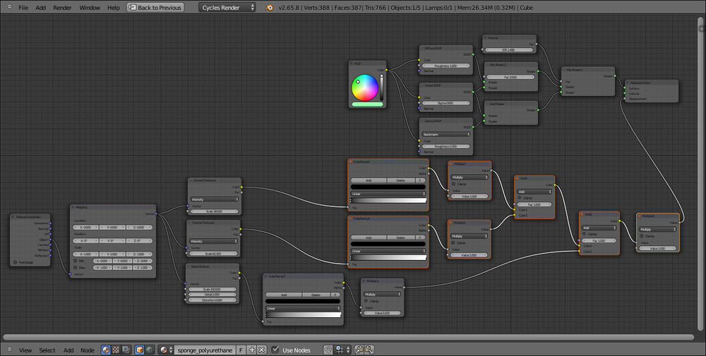
- Add a Texture Coordinate node (Shift + A | Input | Texture Coordinate), a Mapping node (Shift + A | Vector | Mapping), two Voronoi Texture nodes (Shift + A | Texture | Voronoi Texture) and a Noise Texture node (Shift + A | Texture | Noise Texture).
- Place the three textures horizontally in a row like this: Voronoi, Voronoi, and Noise. Rename the first texture Voronoi Texture1 and the second one Voronoi Texture2.
- Connect the Object output of the Texture Coordinate node to the Vector input socket of the Mapping node, and a the Vector output of this latter to the Vector input sockets of the three texture nodes.
- Set the Scale of the Voronoi Texture1 node to 38.000, the Scale of the Voronoi Texture2 node to 62.300, and the Scale of the Noise Texture node to 300.000.
- Add three ColorRamp nodes (Shift + A | Convertor | ColorRamp) and connect the Color output of each texture to the Fac input socket of each ColorRamp node. Rename the first one ColorRamp1, the second one ColorRamp2, and the third ColorRamp3.
- Add three Math nodes (Shift + A | Convertor | Math) and connect the color output of each ColorRamp node to the first Value input socket of each Math node. Set the operation for all the three math nodes to Multiply and rename the first one Multiply1, the second one Multiply2, and the third Multiply3. Set the second Value of the Multiply1 and Multiply2 nodes to 1.000 and the second Value of the Multiply3 node to 0.100.
- Add a Mix node (Shift + A | Color | Mix) and connect the output of the Multiply1 node to the Color1 input socket and the output of the Multiply2 node to the Color2 input socket; change the Blend Type to Add and the Fac value to 1.000. Rename the mix node Add1.
- Press Shift + D to duplicate the Add1 node and rename it Add2; connect the output of the Add1 node to the Color1 input socket and the output of the Multiply3 node to the Color2 input socket of the Add2 node.
- Add a Math node (Shift + A | Convertor | Math), set the operation to Multiply, and rename it Multiply4; connect the output of the Add2 node to the first Value input socket and set the second Value to 1.000.
- Connect the output of the Multiply4 node to the Displacement input socket of the Material Output node.

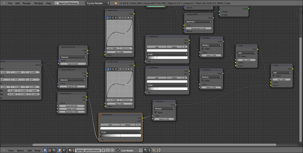
- Now box select (press B, then click with the left mouse button to drag the selection on the objects) the ColorRamp1 and ColorRamp2 nodes, the Multiply1 and Multiply2 nodes, the two Add nodes, and the Multiply4 node; press G and move them to the right, to make room for new nodes to the left side:
- Add an RGB Curves node (Shift + A | Color | RGB Curves) and paste it between the Voronoi Texture1 node and the ColorRamp1 node. Rename it RGB Curves1. Click on the curve to add a control point and in the coordinates slots under the node main window set the X = 0.26111 and the Y = 0.50000; click to add a second control point and write X = 0.73889 and Y = 0.51111.
- Press Shift + D to duplicate the RGB Curves1 node, paste it between the Voronoi Texture2, and the ColorRamp2 nodes and rename it RGB Curves2.
- Go to the ColorRamp1 node and move the white color marker 3/4 to the left; go to the ColorRamp2 and do exactly the same. Go to the ColorRamp3 node and move the white color marker to the middle of the slider.
From step 2 to step 6 we built the basic shader of the sponge material and the color. As you can see in the Rendered camera view, without the bump pattern, there is a visible artifact in the more distant side of the mesh; this is due to the Smooth shading we have set at step 13 of the Getting ready section of this recipe; setting the shading to Flat again will remove the artifact, but will show the blocky faces of the deformed sponge mesh. By the way, because of the bump pattern and of the fact that the mesh is subdivided, this is not trivial and anyone of the two solutions (smooth with artifact or flat but blocky) is fine.
From step 7 to step 20 we built the bump pattern.