
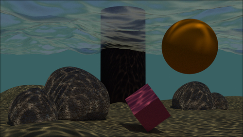
In this recipe, we will create an underwater environment, looking especially at a fake caustic effect projected by the water's wavy surface and at the deep "atmospheric" perspective, obtained by a per material dedicated node group, as shown here:

Let's start by preparing the scene:
- Start Blender and switch to the Cycles rendering engine. Select the cube and go in edit mode, scale it 21 times bigger (press A to select all the geometry and then press S, digit 21, and hit Enter), then scale it on the Z axis to
0.300(press S, followed by Z, digit .3, and hit Enter). - Go out of edit mode, switch to the Objects Modifiers window, and assign a Subdivision Surface modifier. Set the type of subdivision to Simple and the Subdivision value for both the View and the Render levels to
4. - Add a second Subdivision Surface modifier and set the type of subdivision to Simple and the Subdivision value for both the View and the Render levels to
2. - Now assign an Ocean modifier. Set Geometry to Displace, Spatial Size to
20, and Resolution to12. - Go in the Object Data window and click on the + icon under UV Maps to add a set of UV coordinates. There is no need to unwrap the cube.
- Press N and in the Transform panel set these values for the cube: Location to X 3.22600, Y 2.79600, Z -0.20400.
- Be sure to be at frame 1 and place the mouse in the modifier's Time slot, press I to add a key for the animation. Go at frame 25, change the Time value from
1.00to2.00and press I again to set a second key. - In the Screen lay-out button at the top, switch from Default to Animation. In the Graph Editor window, press T and go to Linear and press Shift + E to go to Linear Extrapolation to make the ocean animation constant and continuous.
- Rename the cube as
Ocean_surface.
- Move the camera below the ocean surface (Location set to X 20.000, Y 0.15000, Z -2.50000, and Rotation set to X 92°, Y 0°, and Z 90°) and then go in Camera view (press 0 from numpad).
- Add a cube, a UV Sphere, and or whatever other object you want, floating under the ocean surface. Provide them very simple and colored Diffuse materials. Also add a big cylinder on the background, close to the end of the ocean's cube, half immersed in the water and half standing in the air and assign a simple Diffuse material to it too.
- Go to the World window, click on Use Nodes, and then click on the little square with a dot on the right-hand side of the color slot. From the resulting menu, select Sky Texture.
- Select the lamp, click on Use Nodes, and set a yellowish color for the light (R 1.000, G 0.989, B 0.700). Turn it to Sun and set the Size value to
0.010and the Strength value to2.500. Set Rotation values as: X 22°, Y -7°, and Z 144°; as you already know, the location doesn't matter for a Sun lamp. - Go to the Render window and under the Sampling tab set the Clamp value to
1.00and the samples to50for Preview and100for Render. Under the Light Paths tab, check the No Caustics option. - Now add a plane, place it at Z location equal to
-5.70000, and go in edit mode. Scale it 30 times bigger (press A to select all the geometry, followed by S, digit 30, and hit Enter). Using the Specials menu (press W), subdivide the plane five or six times. Activate the Proportional Editing (PET) tool, randomly select vertexes, and move them up to model the dunes of the ocean bed. Next, come out of edit mode, smooth using the Tools panel, and assign a Subdivision Surface modifier at level 2. Rename itOcean_bed. - Add a cube, in edit mode subdivide it a couple of times (press W and go to Subdivide Smooth). In the Proportional Editing mode and by selecting vertexes, quickly model a big round rock. Duplicate it three or four times, rotating and scaling the copies and place them scattered on the ocean bed.
First, the easy steps, where we'll append already made materials to re-use them:
- From the
1301OS_03_rock_procedural.blendfile, append theRock_procedural_01material. Select the rocks and assign the just appended material. Change the two Diffuse colors to R 0.553, G 0.576, B 0.608 and R 0.567, G 0.391, B 0.314 respectively. - From the
1301OS_03_ground.blendfile, append theground_01material, select the ocean bed and assign this material.
Now, to the more complex steps:
- From the
1301OS_05_ocean.blendfile, append theocean_surfacematerial, select the ocean surface's cube and assign this material. Rename it asocean_surface_under. - Go in edit mode, select only the upper faces of the ocean cube. Press Crtl + I to invert the selection. In the Material window under the Properties panel, click on the + icon on the right (Add a new material slot), rename the new material as
Null(or whatever makes sense for you), and click on the Assign button. Now the ocean cube has two materials: the transparent water surface and the opaque sides/bottom (a simple white Diffuse material). After this, go out of edit mode. - In the Material window, click on the ocean_surface_under material to select it. In the Node Editor window, delete the Foam and the Foam_location node groups and also delete the two Mix nodes. Just to make things clearer, ungroup (press ALT + G) the remaining Ocean_water node group.
- For the moment, place the Ocean water and the Mix Shader nodes ideally aside. Add a Texture Coordinate node (press Shift + A and go to Input | Texture Coordinate), a Mapping node (press Shift + A and go to Vector | Mapping), and an Image Texture node (press Shift + A and go to Texture | Image Texture). Connect the UV output of the Texture Coordinate node to the Vector input of the Mapping node and the Vector output of this one to the Vector input socket of the Image Texture node.
- In the Image Texture node, load the
caustics_tileable_low.pngtexture and set the color space to Non-Color Data. - Add a Diffuse BSDF shader and a Transparent BSDF shader. Add a new Mix Shader node. Connect the Diffuse output to the first Shader input of this Mix Shader node and the Transparent shader output to the second one. Connect the color output of the Image Texture node to the color input socket of the Transparent BSDF shader and the Alpha output to the Fac input of the same Mix Shader node.
- Now connect the output of this second Mix Shader node to the first and still empty Shader input socket of the first Mix Shader node.
- Add a Light Path node (press Shift + A and go to Input | Light Path) and connect the Is Camera Ray output to the Fac input of the first Mix Shader node, as shown here:

What is missing now is the underwater deep atmospheric perspective effect. There are several ways to obtain this, for example, by compositing a Mist pass rendered in Blender Internal, but we are going to do it with a node group assigned to each one of the different materials:
- Add a Camera Data node (press Shift + A and go to Input | Camera Data), a Math node (press Shift + A and go to Convertor | Math), an Emission node (press Shift + A and Shader | Emission), and a Mix Shader node (press Shift + A and go to Shader | Mix Shader).
- Connect the View Z Depth output of the Camera Data node to the first Value input of the Math node. Set the Math node operation to Multiply and the second Value to
0.030, check the Clamp option. Connect the Multiply node output to the Fac input socket of the Mix Shader node. - Connect the Emission output to the second Shader input of the Mix Shader node and set the color to R 0.040, G 0.117, B 0.124.
- Select all these new nodes and press Crtl + G to make a group. Click and drag the first Shader input socket of the Mix Shader node to expose it on the left, do the same on the right for the Shader output socket. Rename the group as Fog_underwater, as shown here:

- Close the group (press Tab to go out of edit mode) and paste it just before the Material Output node of every material (in our scene, it will show eight users if the Fake User option is also selected).

First of all, why a cube for the ocean surface instead of the simpler plane?
The reason is very simple: in Cycles the World emits light and the only way to avoid this is to set its color to a pitch black (or by a combination of the Light Path node with the World materials, but this is another story). In our scene, the World is set to a bright blue sky color and, with a plane, the underwater objects and the ocean bed as well would have been lit too much from the sides and from the bottom, thereby giving an unnatural result. A cube, instead, envelops all the underwater elements, limiting the lighting to the Sun lamp passing through the surface and projecting the image textured caustics—which is a more natural behavior.
The image texture that we assigned to the water material is to obtain a textured transparency effect. The water surface now is actually opaque and transparent accordingly to the black and white values of the textures, so as to allow the Sun lamp's light to pass through and project the caustics.
Thanks to the Is Camera Ray output of the Light Path node, the caustics image texture is not directly renderable on the ocean surface but still has an effect on the other materials. Because Is Camera Ray is equal to 1, the rays starting from the camera and directly hitting the ocean surface can render only the "clean" water material plugged in the second input socket of the Mix Shader node, while the transmitted caustics (plugged in the first socket equal to 0) get rendered.
Finally, the Fog_underwater node group is simply an emitter material colored as the background (in this case, a deep green) and mapped on every underwater material accordingly to the Z depth of the camera (but it works also out of camera view). The "density" of the fog is set by the Multiply node's second Value; for the ocean body, a value of 0.030 seems good enough. The camera's Z axis must not be confused with the global coordinate's Z axis, which in Blender is the vertical blue line visible in the 3D view. The camera's Z axis, instead, is the ideal line connecting the starting point of view to any visible element in the scene.
Note that we didn't expose the values of the nodes in the Fog_underwater group. This is so because we can tweak, in edit mode, the internal values of just one node to automatically update all the fog group instances assigned to the other materials, and we know that the values exposed on the group interface would overwrite the internal settings working only for that single node instance.
