
Chapter 3. Simple projects: input and output
- Looking at the analog world
- Reading an analog input
- Producing sound from a speaker
- Building a pentatonic keyboard
In the previous chapter, we looked at the digital side of the Arduino, building a series of incremental projects that showed off Arduino features like digital inputs and outputs and interrupts. In this chapter we’re going to look at another aspect of the Arduino and how it interfaces with the world around us.
In basic terms, the world around us can be split into two parts—digital and analog—and in this chapter we’re going to investigate interacting with the analog part. We’ll once again start from a basic component, a potentiometer, which reads analog inputs into the Arduino. Then we’ll experiment by adding a sensor—a piezo transducer that can be used as an analog input or output. We’ll round up by adding four more piezo transducers and a small speaker to build a working five-key pentatonic keyboard.
These are the components required to complete this chapter:
- An Arduino board.
- A breadboard and a selection of jumper leads.
- A small potentiometer. (A trimpot is ideal, as it can easily plug into a breadboard.)
- Five zener diodes, 0.5 watt 5V1. (We used a BZX55C5V.)
- Five uncased piezoelectric transducers (knock sensors) with wire connectors.
- Five resistors, 1M ohm (1 mega ohm).
- One resistor, 1k ohm.
- A small speaker, 8 ohm.
Let’s start by learning the basics of working in analog.
3.1. Time to get analog
In previous chapters, you experimented with buttons that could be either on or off, but what if you wanted to measure an analog input like a photo or force-sensing resistor? If the Arduino was purely a digital device, you wouldn’t be able to measure these devices, which would limit the scope of your projects. Luckily, the Arduino has this covered and can interact with the analog world as well.
The Arduino can alter the brightness of an LED not by varying the voltage applied to it but by using a special technique called pulse width modulation, or PWM (more on this in a moment). In addition to providing an analog output using PWM, the Arduino can also take an analog input of between 0 and 5 volts.
The standard Arduino has six analog inputs labeled ANALOG IN A0, A1, A2, A3, A4, A5; in addition, there are six analog outputs.
In this chapter, we’ll concentrate on the analogRead function; we’ll leave analogWrite to a later chapter.
Let’s start by taking a look at the difference between digital and analog devices.
3.1.1. What’s the difference between analog and digital?
So what’s the difference between the analog and digital worlds? In the digital world, everything has two states; a switch can only be on or off, an LED is either lit or it isn’t, you’re either awake or asleep. These states can be thought of in a variety of ways as ones or zeros, on or off, high or low. The Arduino digital pins work in the same way; when set as an output, they’re either 0 or 5 volts, with a 0 voltage being a logical zero and 5 volts being logical one. In the analog world, things have a range of values. Music has notes that span a range of frequencies, a car accelerates through a range of speeds, a sine wave flows smoothly between maximum and minimum values, and temperature varies between a maximum and minimum.
We often want to explore the analog world, and the Arduino has six analog inputs that help us with this. But the Arduino is still a digital device, so you need a means of converting the input signal to a digital representation. This is done with an analog-to-digital converter (ADC). Table 3.1 shows the resolution, voltage range, and pins used for analog input and output for the Arduino and Arduino Mega.
Table 3.1. The Arduino’s analog resolution and analog input and output pins
|
Analog input |
Analog output |
|
|---|---|---|
| Resolution | 10 bit (0 through 1023) | 8 bit (0 through 254) |
| Voltage range | 0 through 5 volts | 0 through 5 volts |
| Arduino pins | A0 through A5 | Digital pins 3, 5, 6, 9, 10, 11 |
| Arduino Mega pins | A0 through A15 | Digital pins 2 through 13 |
In the next section, you’re going to use a potentiometer to provide an analog input that you can manually vary, and you’ll instantly see the effect of these changes by displaying the results using the serial monitor.
3.1.2. Reading a potentiometer
A potentiometer is one of the simplest ways to show how the Arduino’s analog input works. Potentiometers come in all shapes and sizes, as shown in figure 3.1, and they’re used in many different devices all around us. If you have a stereo with a rotary volume control, it’s likely based on turning a potentiometer. Other examples include dimmer controls on lights and temperature controls on electric cookers or ovens. Despite the different shapes and sizes, they all have some means of varying resistance, either in a linear or logarithmic way.
Figure 3.1. A selection of potentiometers

The majority of potentiometers have three connections; the middle one is usually called the wiper and is used to vary the resistance by moving a contact along a fixed resistor. For this chapter, you want a potentiometer that varies resistance linearly and that’s suitable for plugging into a breadboard; trimpots are often ideal.
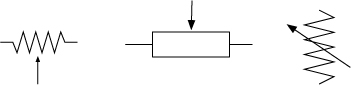
Figure 3.2 shows the schematic symbols for a potentiometer. The central arrow, known as the wiper, is overlaid over the standard symbol for a resistor and indicates that the resistance is variable.
Figure 3.2. Schematic symbols for a potentiometer: U.S. (left), International (center), Fritzing (right)
Let’s now move on to connecting a potentiometer to the Arduino.
3.1.3. Connecting the hardware
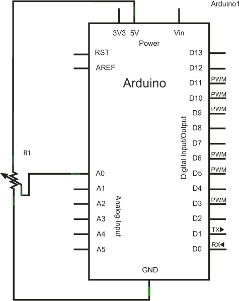
Now that you know which potentiometer to use, let’s get it set up. The circuit diagram shown in figure 3.3 has your potentiometer, labeled R1, connected between five volts and ground, with the wiper connected to analog input A0. As you turn the potentiometer clockwise or counterclockwise, you’ll adjust the voltage between 0 and 5 volts on A0.
Figure 3.3. A circuit diagram showing the potentiometer connected to the Arduino
Plug the potentiometer into the breadboard. The central leg is normally the wiper, and this is the one you want to connect to your analog input, A0. The completed connections are shown in figure 3.4.
Figure 3.4. The potentiometer connected to the Arduino

The potentiometer shown in figure 3.4 doesn’t have a rotary knob, but it can be turned by inserting a pot trimmer tool. If you don’t have a pot trimmer tool, you can use a small slot-head screwdriver instead.
With the potentiometer connected, you can move on to writing a sketch to read values from it.
3.1.4. Sketch to read a potentiometer
The following listing shows the sketch you’re going to use to read an analog value between 0 and 5 volts into analog pin A0.
Listing 3.1. Reading a potentiometer
int sensorPin = A0;
int sensorValue = 0;

void setup(){
  Serial.begin(9600);
}

void loop(){
  sensorValue = analogRead(sensorPin);
  Serial.print("Sensor = ");
  Serial.println(sensorValue, DEC);
  delay(10);
}
You don’t need to set the sensorPin as an input during the setup routine because all analog input pins are set by default to be input. The sensorValue variable stores the value read by the analogRead function, which returns a number between 0 and 1023 inclusive, with 0 representing 0 volts and 1023 representing 5 volts.
The 10 millisecond delay between each reading gives the Arduino’s ADC time to settle and capture an accurate reading. The DEC in the Serial.println(sensorValue, DEC); line instructs the println function to output data as base decimal. Other options include HEX (hexadecimal), BIN (binary), and OCT (octal).
3.1.5. Upload and test
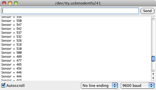
After entering the sketch into the IDE, verify that it compiles, and then connect the Arduino to your computer and upload the sketch to it. Load the serial monitor in the IDE and rotate the potentiometer fully clockwise and counterclockwise. You should see the number output to the serial monitor changing as the potentiometer is rotated. Example output is shown in figure 3.5.
Figure 3.5. Output displayed as the potentiometer is rotated
You’ve now seen how to read a value into one of the analog input pins. In the next section, you’re going to connect the Arduino to a piezoelectric transducer. For this you’ll need some additional components, because a piezoelectric transducer can produce some very high voltages that could potentially damage the Arduino.
3.2. A piezoelectric transducer
If you’ve ever received a birthday card that plays a tinny version of “I’m So Excited” by the Pointer Sisters when opened, you’ve likely encountered a piezoelectric transducer being used as a speaker. Piezoelectric transducers are also found in a variety of other devices, including mobile phones, door buzzers, and underwater sonar.
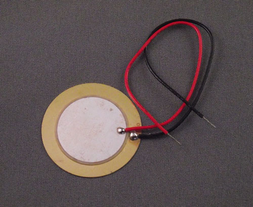
Figure 3.6 shows a typical piezoelectric transducer that can be used to produce sounds similar to those used in some musical cards.
Figure 3.6. A typical piezoelectric transducer used in some musical cards and as sensors on drum kits
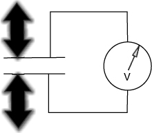
How do they work? The word piezoelectricity means “electricity resulting from pressure.” When a piezoelectric device is squeezed, it produces an electric charge, as shown in figure 3.7. A typical application for this with an Arduino is to use the transducer as a knock sensor. When the transducer is hit or knocked, the Arduino detects this and performs the required action, such as switching on an LED or producing a tone from a speaker.
Figure 3.7. When a piezoelectric transducer is distorted, it produces an electric charge; alternately squeezing and releasing the transducer will produce a varying voltage.
Conversely, when an electric charge is applied to a piezoelectric transducer, it distorts or changes shape as shown in figure 3.8. If you apply a varying voltage at a certain frequency, the movement of the transducer can cause it to produce a sound or note. It’s in this mode that piezoelectric transducers are used in musical greeting cards or as buzzers.
Figure 3.8. When varying voltage is applied to a piezoelectric transducer, the transducer’s shape distorts.

As you’ve seen, a single piezoelectric transducer can be used either as an input or an output device. Sonar devices, which have at their heart a piezoelectric transducer, send out a sound signal and listen for the echo. This is most familiar as the classic ping sound in submarine movies. The time it takes for the ping to return gives an indication of how far away a target is. We’ll look at another example of this in chapter 6 when the Devantech SRF05 is used as a rangefinder.
Now that you’ve had a quick look at piezoelectric transducers and how they work, you’re going to use a piezoelectric transducer as a knock sensor. When the Arduino detects that the knock sensor has been hit or knocked, it will light up an LED.
3.2.1. The circuit diagram
For this project, you’ll need the following components:
- An Arduino.
- A breadboard and jump wires.
- A zener diode 0.5 watt 5V1. (We used a BZX55C5V.)
- An uncased piezoelectric transducer. (We used a 27 mm one from eBay.)
- A resistor, 1M ohm.
You’ll use an uncased piezoelectric transducer because this will give better results than a cased one.
When hit, piezoelectric transducers can produce very high voltages, which are capable of causing damage to the Arduino. A zener diode is used to protect the Arduino from these high voltages, and the resistor is there to bleed off the voltage from the transducer.
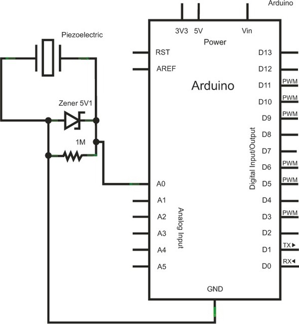
Figure 3.9 shows the complete circuit diagram. Note the orientation of the zener diode and how both it and the resistor are parallel to the piezoelectric transducer.
Figure 3.9. A piezoelectric transducer attached to analog input A0. The zener diode protects the Arduino from the high voltages produced by the transducer when it’s struck.
Now that you’ve looked at the circuit diagram, you can move on to assembling the circuit on your breadboard.
3.2.2. Connecting the hardware
The circuit has three main parts in addition to the Arduino: a 5.1 V zener diode, a 1M ohm resistor, and a piezoelectric transducer. As already described, the zener diode and the resistor are connected in parallel to the piezoelectric transducer.
Start by placing the three components onto the breadboard, paying careful attention to the polarity of the piezoelectric transducer, which normally has a red and black wire presoldered onto it using a special low-melting-point solder. The black wire connects to the GND part of the circuit, and the red connects to the Arduino’s analog input A0.
Diodes are two-terminal devices that have low resistance to current flow in one direction, and high (ideally infinite) resistance in the other. Zener diodes are a special type of diode that is designed to allow current to flow in either direction once its breakdown or knee voltage is exceeded.
The zener diode needs to be connected the correct way so that it protects the Arduino’s analog input from any voltages exceeding 5 volts. Conventionally, the cathode or negative end of the diode, normally designated with a black band, would be connected to GND, but in your circuit you’re going to reverse-bias the diode and connect it the other way so that the cathode is connected to the positive side of the circuit. The zener diode works by only conducting electricity when its breakdown voltage is exceeded, which in this case is 5.1 volts. Any voltages over 5.1 volts will cause the diode to connect and short circuit the voltage to GND, thus protecting the input of the Arduino.
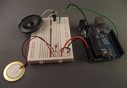
When the three components have been connected to the breadboard, you can make the final connections to the Arduino’s GND and analog input A0. Figure 3.10 shows a picture of the completed circuit, including the connections to the Arduino.
Figure 3.10. The completed circuit connected to the Arduino. Note the orientation of the zener diode and the polarity of the piezoelectric transducer.

With your components connected together and to the Arduino, you can now move on to writing your sketch and interfacing the Arduino with your piezoelectric transducer.
3.2.3. Sketch to measure output from a piezoelectric transducer
To start with, you’re going to use the sketch that was shown in listing 3.1. If you didn’t save the sketch before, create a new sketch and type in the listing.
Go ahead and plug in the Arduino to the USB port, upload your sketch, and start the serial monitor. Initially the serial monitor should just print 0 values. Now try lightly hitting or squeezing the transducer, and notice how the sensor values change. A typical output is shown in figure 3.11.
Figure 3.11. The serial monitor showing the results of squeezing or tapping the piezoelectric transducer

When the transducer is hit, the numbers should quickly rise to a maximum value and then fall back to 0. The differing values indicate how hard the transducer is squeezed or hit: the higher the value, the harder it has been hit or squeezed. If nothing happens, check your connections, paying careful attention to the orientation of the transducer and the zener diode.
You’re now going to amend your sketch so that only values over a certain threshold are printed. You can either alter your existing potentiometer sketch or create a new one. The new sketch is shown in the following listing; save this sketch as threshold.
Listing 3.2. Threshold for a piezoelectric transducer
int sensorPin = A0;
int sensorValue = 0;
int threshold = 200;

void setup(){
  Serial.begin(9600);
}

void loop(){
  sensorValue = analogRead(sensorPin);
  if (sensorValue > threshold) {
    Serial.print("Sensor = ");
    Serial.println(sensorValue, DEC);
  }
  delay(10);
}
In listing 3.2, you set a threshold value of 200. In the loop part of the sketch, you’re only going to print out sensor values that are greater than this threshold.
Now let’s move on to testing it.
3.2.4. Upload and test
After entering the sketch shown in listing 3.2, verify that it compiles and then upload it to the Arduino. Load the serial monitor and try hitting the transducer with varying degrees of force. Note that the harder you hit it, the higher the sensor value that’s returned. Figure 3.12 shows some example output.
Figure 3.12. Output from hitting the piezoelectric transducer with varying degrees of force

Now you have a sketch that checks the value at analog input A0 and prints the value if it exceeds a certain threshold. Next, you want to make it do something more useful than just report a value. If you added a speaker to your circuit, you could get the Arduino to play a note or tone when the piezoelectric transducer is hit, and that’s what you’re now going to do.
3.2.5. Circuit with added speaker
For this section, you need to add two components:
- A small speaker, 8 ohm
- One 1k ohm resistor
Figure 3.13 shows the circuit from figure 3.9 with the speaker and resistor added.
Figure 3.13. A speaker has been added to the circuit, with which you’ll output a tone.

Now it’s time to assemble the circuit onto a breadboard.
3.2.6. Connecting the hardware
Connect the hardware with the speaker connected to digital pin 8 through a 1k ohm resistor. The completed circuit is shown in figure 3.14.
Figure 3.14. Connections with the addition of the speaker
We had to solder a couple of jumper wires to the speaker because the original speaker wire was too soft to plug directly into the breadboard. If you don’t have soldering equipment, you can either use some insulating tape to tape the wires onto the wire jumpers or use alligator clips.
Once all the components have been connected, you can move on to writing your sketch.
3.2.7. Sketch to generate a tone
Listing 3.3 shows the code for your new sketch, in which you set three new variables:
- toneDuration denotes how long a tone is played in milliseconds.
- toneFrequency sets the frequency of the tone being played in Hertz (262 Hz is middle C).
- speakerPin defines the pin to which the speaker is connected.
Listing 3.3. Generating a tone in the speaker
int sensorPin = 0;
int sensorValue = 0;
int threshold = 200;
int toneDuration = 40;
int toneFrequency = 262;
int speakerPin = 8;

void setup(){

}

void loop(){
  sensorValue = analogRead(sensorPin);
  if (sensorValue > threshold) {
    tone(speakerPin,toneFrequency,toneDuration);
  }
}
In this sketch, you’re using one of the Arduino’s built-in libraries, tone, which can take three arguments:
tone (pin, frequency, duration)
pin is the pin to which the tone is output; frequency is the frequency of the output tone; and duration is the time in milliseconds to play the tone. If the duration parameter isn’t provided, the tone will play until a noTone command is issued to it:
noTone(pin)
In this sketch, the tone is only played if the sensorValue is greater than the threshold. Now let’s try it out.
3.2.8. Upload and test
After verifying that the sketch compiles with no errors, connect the Arduino to your computer and upload the sketch to it. Try hitting the piezoelectric transducer and check that a tone is produced in the speaker. If no sound is produced, try checking all your connections.
Tip
If your speaker is very quiet or you’ve checked all the connections and you still hear no sound, try increasing the toneDuration from 40 to 1000 or changing the value of toneFrequency.
Once everything is working, you can change the value of the toneFrequency variable to alter the note that the speaker plays. The higher the frequency, the higher the pitch; the lower the frequency, the lower the pitch. You can also try altering the value of the threshold variable. The lower the value, the softer you can hit the transducer to play a note from the speaker.
In the next section, you’re going to add more piezoelectric transducers to your circuit so you can make a keyboard, with the transducers acting as keys.
3.3. Making a pentatonic or five-tone keyboard
The word pentatonic comes from penta, meaning five, and tonic, meaning tones. A pentatonic scale has five notes per octave, compared to the heptatonic scale, which has seven notes per octave. Pentatonic scales are popular the world over and are featured in a variety of musical types and styles including blues, Celtic, jazz, and ancient Greek music. The pentatonic scale is ideal for introducing children to music. Its simplicity and ease of use make it easy to quickly produce recognizable tunes, and many nursery rhymes are based on a pentatonic scale.
You’re now going to build the final project in this chapter by adding another four piezoelectric transducers to your existing circuit, for a total of five piezoelectric transducers, which you’ll use as keys. When each key is hit, it will produce a different note, or tone, from the speaker—hence, a pentatonic keyboard.
3.3.1. Circuit diagram
Each additional piezoelectric transducer requires a 1M ohm resistor and a zener diode in parallel, exactly the same as the first one you used. Figure 3.15 shows the complete circuit diagram. It looks complex with the additional components, but you’re only repeating the circuit used in figure 3.9.
Figure 3.15. Circuit diagram for pentatonic keyboard

The circuit diagram shows the five piezoelectric transducers, each with a parallel resistor and diode. You use the analog inputs A0 through A4 as inputs to the Arduino.
Now it’s time to connect the hardware together.
3.3.2. Connecting the hardware
Add the additional piezoelectric transducers, resistors, and diodes to the breadboard. Pay careful attention to the orientation of the piezoelectric transducers and the zener diodes. As you can see in figure 3.16, I’ve made a common ground using one of the horizontal strips on the breadboard.
Figure 3.16. The pentatonic keyboard fully assembled
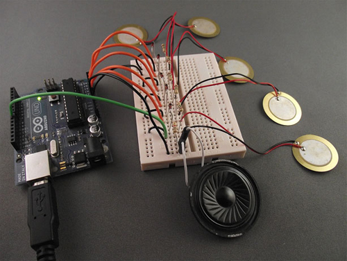
Having completed the assembly of the keyboard, it’s a good idea to check that each transducer is connected correctly. You can do this by uploading the sketch from listing 3.3 to the Arduino and testing that the transducer connected to analog input A0 produces a sound from the speaker when hit. If no sound is produced, check that all connections are properly made; it’s easy to plug a component into the wrong hole on the breadboard, because the board is now getting crowded. Also check the orientation of the zener diode and the polarity of the piezoelectric transducer.
Once everything is working, you can test the other transducers one at a time by making a small change to the sketch. Change the value of the sensor pin in the topmost line from int sensorPin = 0 to int sensorPin = 1. Upload the revised sketch to the Arduino and test the transducer connected to analog input A1. When the transducer is hit, a sound should be produced from the loudspeaker.
Repeat this procedure for the other three transducers by changing the value of the sensorPin each time. Once all the piezoelectric transducers have been tested and are working, you can move on to the code for the pentatonic keyboard sketch.
3.3.3. Sketch to create a pentatonic keyboard
The code for the pentatonic keyboard is shown in the following listing. You can either adapt your existing sketch or create a new one and type in the listing.
Listing 3.4. Pentatonic keyboard sketch
int sensorValue = 0;
int threshold = 50;
int toneDuration = 10;
int speakerPin = 8;

int tones[]={262,294,330,392,440};

void setup(){

}

void loop(){
  for (int sensorPin = 0; sensorPin < 5; sensorPin++) {
    sensorValue = analogRead(sensorPin);
    if (sensorValue > threshold) {
      tone(speakerPin,tones[sensorPin],toneDuration);
    }
  }
}
This sketch loads the frequencies of the notes into the tones array; the tones used are based on the major pentatonic scale and middle C:
The loop routine tests the value of each analog input in turn. When a tap on a piezoelectric transducer is detected, and the value returned is above the threshold value, the corresponding tone is played through the speaker for 10 milliseconds.
Note
In this sketch, the threshold is set at 50. You previously used a value of 200, but we found during testing that one of the transducers needed to be hit much harder than the others, so we reduced the threshold to 50, thus making the keys more sensitive.
Once all the code has been typed into the sketch, save it with a memorable name. You can then move on to uploading and testing your pentatonic keyboard. You might even want to try playing a couple of tunes.
3.3.4. Upload and test
Verify that the sketch compiles. When it does, connect the Arduino to your computer and upload the sketch to it. Now you can test that everything is working by tapping the transducers and making sure each produces a tone. Try playing some simple tunes. It might sound a little tinny because you’re only using a small speaker, but you’ve built your own working keyboard.
You can alter the notes by changing the frequencies loaded into the tones array. You might try the C minor pentatonic scale with the following values:
- C = 262 Hz
- E = 311 Hz
- F = 349 Hz
- G = 392 Hz
- B = 466 Hz
By loading different frequencies into the tones array, you can produce very different sounds and tunes.
The main thing is to have fun and show off your new creation. Using the major pentatonic scale, try the following note progressions. See if you can recognize the tunes, or better yet, see if someone else can recognize them.
- GGAGCB GGAGDC—Hint: everybody has one of these each year.
- CDECCDEC EFG EFG—French brother.
- CCGGAAG FFEEDC—Heavenly.
Now try making some of your own note progressions. One of the beauties of using the pentatonic scale is that it’s relatively easy to produce pleasant-sounding melodies.
3.4. Summary
In this chapter you looked at the analog-input side of the Arduino using analogRead. You experimented by reading values from two separate analog devices, a potentiometer and a piezoelectric transducer. You saw how the analog signal is converted to a digital format using an analog-to-digital converter (ADC) that can be interpreted by the Arduino. This approach allows you to confidently read data from many other analog devices.
Your final project in this chapter made extensive use of analogRead, and you built a pentatonic keyboard with five piezoelectric transducers that each produced a different note when hit. Hopefully you had some fun showing off your musical prowess to anyone who would listen, even if the sound was a little tinny.
In the next chapter, you’ll look at the two main ways of extending the Arduino: the first using software libraries that enable the Arduino to communicate with other sensors, such as two-wire devices and SPI communication, and the second using hardware shields that plug directly into the headers of the Arduino. You’ll also look at a couple of the most common shields.