Chapter 20
Label Styles
Styles control the display properties of AutoCAD® Civil 3D® objects and labels. The creation of proper styles and settings can make or break your experience with Civil 3D. Understanding and applying styles correctly can mean the difference between getting a job out in several hours, and fighting with your project drawing for days.
This chapter is organized by style type. First, read the chapter to be introduced to the style concepts in a logical manner. Later, when you use this chapter as a reference to build styles, you will likely jump around to the examples that meet your needs.
In this chapter, you will learn to:
- Override individual labels with other styles
- Create a new label set for alignments
- Create and use expressions
- Apply a standard label set to profiles
Label Styles
The best design in the universe is not worth anything unless it is labeled properly. Civil 3D labels are smart objects that are dynamically linked to the object they are labeling. Civil 3D labeling is customizable to fit the needs of your design and local requirements.
When talking about labels in Civil 3D, keep in mind that you are not just talking about text. Labels can contain lines and blocks if desired. Label styles control the size, contents, and precision of text. Label styles also control how leaders are applied when the label is dragged away from its initial position. You will even work with some labels that contain no text at all!
General Labels

On the Settings tab, you see a complete list of objects that Civil 3D uses to build its design model. Each of these has special features unique to the object being described, but there are some common features as well. The General collection contains settings and styles that are applied to various objects across the entire product.
The General collection serves as the catchall for styles that apply to multiple objects, and for settings that apply to no objects. For instance, the Civil 3D General Note object doesn't really belong with the Surface or Pipe collections. It can be used to relate information about those objects, but because it can also relate to something like “Don't Dig Here!” or a Northing-Easting of an arbitrary location, it falls into the General category.
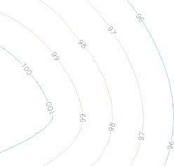
The Label Styles collection allows Civil 3D users to place general text notes or label single entities while still taking advantage of the flexibility and scaling properties. With the various Label Styles shown in Figure 20.1, you can get some idea of their use.
Label styles are a critical part of producing plans with Civil 3D. In this chapter, you'll learn how to build a new basic label and explore some of the common components that appear in every label style throughout the product.
Frequently Seen Tabs
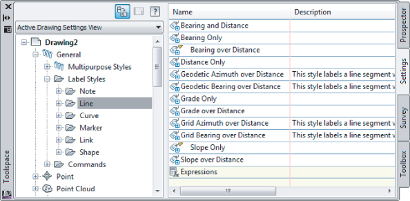
To get into a label style, find the appropriate label type in the Settings tab of Toolspace. Right-click the style you wish to modify (or copy) and select Edit.
All styles, regardless of type, have a few things in common:
Information Tab
The Information tab, shown in Figure 20.2, controls the name of the style.
If desired, you can create a description. This information will appear as a tooltip as you browse through the Settings tab.
On the right side of the dialog, you will see the name of the style, the date when it was created, and the last person who modified the style. These names are initially pulled from the Windows login information and only the Created By field can be edited.
General Tab
The General tab (Figure 20.3) is where the Text Style, Visibility, and Layer options are set for the text item. The Behavior and Plan Readability options control how the text is positioned as it is placed and whether rotation is applied to the object or view it is in. Other options include:
Text Style
This option refers to the base AutoCAD text style used in the label. The available text styles come from the base AutoCAD styles.
Layer
This option defines the layer on which the components of a label are inserted. The overall label may appear on a completely different layer depending on the layers set up in the Drawing Settings.
Orientation Reference
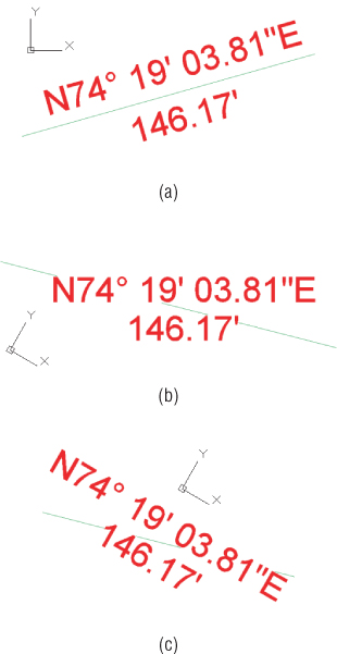
This option controls how text rotation is controlled. Figure 20.4a shows the most common option where the label is aligned with the object. Figure 20.4b shows the text rotated to the view. Even though the view has been rotated, the text still appears parallel with the bottom of the screen. The last, and least used, option for text is the World Coordinate System option, shown in Figure 20.4c. The view is rotated, and the direction of the text rotates with the coordinate system.
Forced Insertion
This option makes more sense in other objects and will be explored further. The Forced Insertion feature allows you to dictate the insertion point of a label on the basis of the object being labeled. Figure 20.5 shows the effects of the various options on a bearing and distance label.
Plan Readable
When this option is enabled, text maintains the up direction in spite of view rotation. Rotating 100 labels is a tedious, thankless task, and this option handles it with one click.
Readability Bias
This option specifies the angle at which readability kicks in. This angle is measured from the 0 degree of the x-axis that is common to AutoCAD angle measurements. When a piece of text goes past the readable bias angle, the text flips direction to maintain vertical orientation, as shown in Figure 20.6. The default Readability angle is 110. A common desired default is 90.1, which would flip any text just after passing a vertical direction.
Flip Anchors With Text
Most users leave this obscure setting at its default, False, and never give it another thought. Figure 20.7a shows what happens to the text insertion points when this option is set to False and readability kicks in. Notice how the text flips to the bottom of the line it is labeling when this setting is set to True, as shown in Figure 20.7b.
Layout Tab
Each label can be made up of several components. A label component can be text, a block, or a line, and the top row of buttons controls the selection, creation, and deletion of these components, as seen in Figure 20.8.

Component Name
Choose the component you want to modify from the Component Name drop-down menu. The components are listed in the order in which they were created. Pay attention to which component is active when you make changes to properties on the Layout tab. The changes you make to properties will only apply to the active component.
Create Component
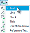
The Create Component button lets you add new elements to enhance your labels. A component can be either Text, Line, Block, Tick, Direction Arrow, or Reference Text. The options will vary depending on the object you are labeling. Not every option is available in every label.
The ability to label one object while referencing another (reference text) is one of the most powerful labeling features of Civil 3D. This is what allows you to label a spot elevation for both an existing and a proposed surface at the same time, using the same label. Alignments, COGO points, parcels, profiles, surfaces, and survey figures can all be used as reference text.

Copy Component
The Copy Component button copies the component currently selected in the Component Name drop-down menu. This will be helpful when you're creating label styles that contain multiple pieces of similar information.

Delete Component
The Delete Component button deletes components. Elements that act as the basis for other components can be deleted, but you will receive a warning. Table tag components, found in curve, line, and parcel segment labels, cannot be deleted.

Component Draw Order
The Component Draw Order button lets you shuffle components up and down within the label. This feature is especially important when you're using masks or borders as part of the label.
You can work your way down the component properties and adjust them as needed for a label:
Name
This option defines the name used in the Component Name drop-down menu and when selecting other components. When you're building complicated labels, a descriptive name goes a long way.
Visibility
When set to True, this option means the component shows on screen. Why create a component that can't be seen? There are cool tricks you can do with styles, as you'll see in the section “Pipe Labels” later in this chapter.
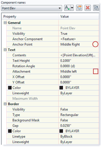
Anchor Component and Anchor Point
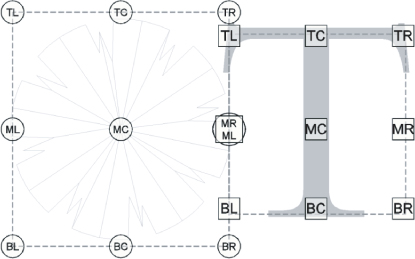
Use these options to control text placement. Anchor Component lets you tell Civil 3D how text (or other label components) relate to the main object you are labeling. See Figure 20.9 and Figure 20.11 for a graphical explanation of how these options relate to each other. The circles represent anchor points and the squares represent attachment.
Text Height
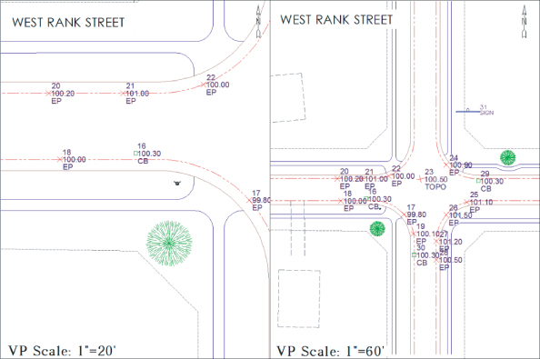
This option determines the plotted height of the label. Text placed by Civil 3D is always annotative. Figure 20.10 shows two viewports showing some COGO points along a road. Even when the viewport scales differ, the text is the same size.
Rotation Angle, X Offset, and Y Offset
These options give you the ability to refine the placement of the component by rotating or displacing the text in an x or y direction. Set your text as close as possible using the anchors and attachments, and use the offsets as additional spacing.
Attachment
This option determines which of the nine points on the label components bounding box are attached to the anchor point. See Figure 20.11 for an illustration.
Color and Lineweight
These options allow you to force the color and lineweight if desired.
Maximum Width
Some labels can get rather lengthy. Instead of letting the label component continue indefinitely across the page, you can use Maximum Width to force word wrap after a specified plotted length. The default setting of 0.00 will not force word wrap.
The final piece of the component puzzle is the Border option. These options are as follows:
Visibility
Use this option to turn the border on and off for the component. Remember that component borders shrink to the individual component; if you're using multiple components in a label, they all have their own borders.
Type
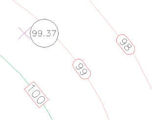
This option allows you to select a rectangle, a rounded rectangle (slot), or a circle border. Figure 20.12 shows examples of the three types of borders.
Background Mask
This option lets you determine whether linework and text behind this component are masked. This option can be handy for construction notes in place of the usual wipeout tools. The surface labels in Figure 20.12 show the background mask in action.
Gap
This option determines the offset from the component bounding box to the outer points on the border. Setting this to half of the text size usually creates a visually pleasing border.
Linetype and Lineweight
These options give you control of the border lines.
Dragged State
When a label is dragged in Civil 3D, it typically creates a leader, and text is rearranged. The settings that control these two actions appear on this tab (see Figure 20.13).
Here are some of the unique options:
Arrow Head Style and Size
These options control the tip of the leader. Note that Arrow Head Size also controls the tail size leading to the text object.
Type
This option specifies the leader type. Options are Straight Leader and Spline Leader. Civil 3D can only have one leader coming from a label.
Display
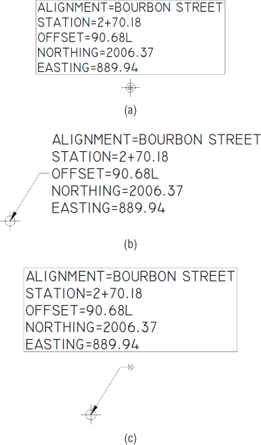
In this option you can choose Stacked Text or As Composed. The Stacked Text option will remove any blocks, ticks, lines, or borders that are components of the label and will realign the text based on the direction you drag. The As Composed option leaves blocks, ticks, lines, or borders intact and adds a leader.
Figure 20.14a shows an alignment label as it was originally placed. Figure 20.14b shows the same label in a dragged state with the Stacked Text option set. Figure 20.14c shows the label in a dragged state with the As Composed option set.
Summary Tab
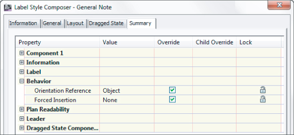
The Summary tab is exactly what it sounds like—that is, a summary of all other settings that exist in the style. The information from other tabs in list form as well as their override status is shown in Figure 20.15.

Like other settings in Civil 3D, there is a hierarchy that helps the user and the software decide which styles take precedence over other styles. There are also items that can be changed at a drawing-wide level and pushed out to object-level labels. Use this ability with caution, as most labels will use their own layers and behave differently depending on the object it is labeling.
In the first exercise, you will set all labels to use the same initial text style:
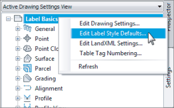
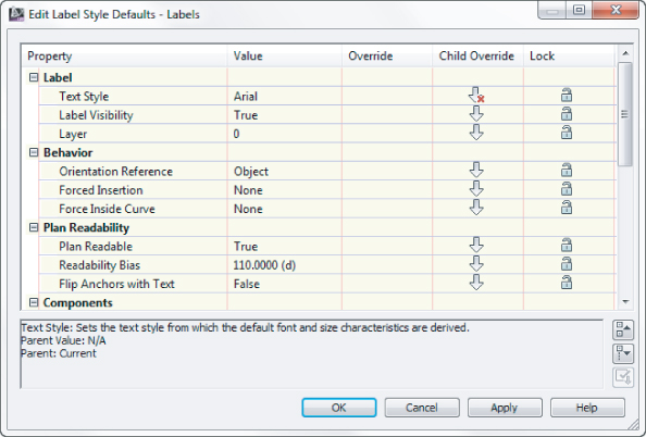
2. From the Settings tab of Toolspace, right-click on the name of the drawing and select Edit Label Style Defaults, as shown in
Figure 20.16.
3. Expand the Label category and change Text Style to Arial.
4. Click the arrow in the Child Override column to force all label styles in this drawing to use the same text, as shown in
Figure 20.17.
5. Do not make any more changes to this dialog, but examine the various options and settings, and click OK.
6. Save the drawing for use in the next exercise.
Getting to Know the Text Component Editor
Few dialogs in Civil 3D inspire expletives the way the Text Component Editor can. The interface is very logical and will do exactly what you tell it to do—not necessarily what you want it to do. Hopefully, with some explanation you will see the reasoning behind its behavior and master it!
To enter the Text Component Editor, from the Layout tab of any text style, click the ellipsis that pops up when you click in the Text Contents area.
Within the Text Component Editor are two main areas:
- The left side is where you select what aspect of the Civil 3D object you want to pull into your label.
- The right side shows what is already in the label.
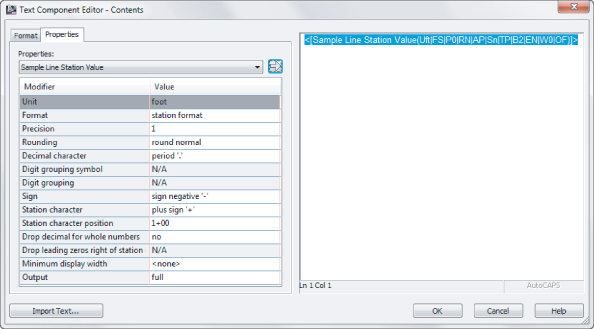
To modify an existing label, highlight the chunk of text on the right side of the dialog. In Civil 3D, “smart” text will always highlight as a unit. Each of the cryptic codes in the label represents a setting for units, precision, or other ways the text can display. What appears on the left is a decoded list of what is currently part of your label. After making changes, don't forget to click the arrow to update the information on the right.
Before adding new text to a label, make sure you don't have any existing text highlighted on the right, to avoid overwriting it.
The Properties list shows everything that can be labeled about the item you are working with. The length of the list varies depending on the object. Here you see the available properties for a contour (left) and a pipe-network structure (right):
Once you pick what you'd like to label, the units, precision, and any other special rounding or formatting you would like to see.
When everything is set, click the arrow next to the Properties list.
To further fine-tune the text, a Format tab sits inconspicuously behind the Properties list. Use this to add special symbols, or to override the color and text style.
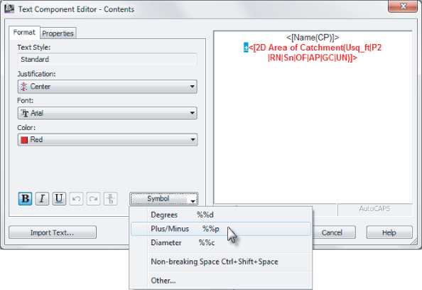
Inevitably, you will forget the arrow that adds or updates the text. You may even click it twice and end up with duplicates! Now that you've been given the heads-up you'll be able to laugh it off, knowing that it happens to even the most seasoned users.
General Note Labels
General Note labels are versatile, non-object-specific labels that can be placed anywhere in the drawing. There are several advantages to using these instead of base-AutoCAD MTEXT. Notes will leader off and scale the same as the rest of your Civil 3D text, and best of all, they can contain reference text.
In the following example, you will create an alternate parcel label that contains reference text. You do not need to have completed the previous exercise to proceed.
1. Continue working in Label Basics.dwg (Label Basics_METRIC.dwg), which you can download from this book's web page.
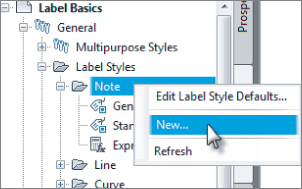
2. From the Settings tab of Toolspace, choose General ⇒ Label Styles ⇒ Note.
3. Right-click on Note and select New (as shown in
Figure 20.18).
4. On the Information tab, name the style Easement Parcel Text.
5. On the General tab, set Layer to C-PROP-TEXT, and set Orientation Reference to View.
6. On the Layout tab, click the field next to Contents under the Text category.
Clicking this will cause an ellipsis button to appear.
7. Click the ellipsis button to enter the Text Component Editor.
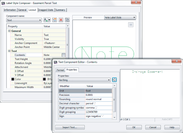
8. On the right side of the Text Component Editor, delete the existing text and replace it with
Drainage Easement, as shown in
Figure 20.19. Click OK.
9. Back in the Layout tab, set Border Visibility to False.

10. Click the flyout next to Create Text Component and select Reference Text.
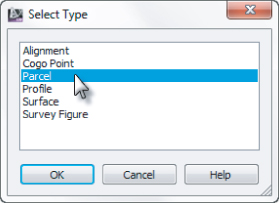
You will be prompted to select the type of reference text, as shown in
Figure 20.20.
11. Select Parcel and click OK.
12. Rename the Reference Text.1 to Parcel Area and make the following changes:
A. Set Anchor Component to Text.
B. Set Anchor Point to Bottom Center.
C. Set Attachment to Top Center.
D. Click the Contents Label Text field ellipsis and enter the Text Component Editor.
13. Remove the existing label text.
14. On the left side of the Text Component Editor, do the following:
A. Set the Properties drop-down to Parcel Area.
B. Set Unit to Acre (Hectares).
C. Set Precision to 0.01.

15. When you have set the properties, click the arrow icon to place the text in the right side of the editor.
16. Click to put your cursor after the previously inserted text. Add ACRES (or HECTARES) after the coding.
17. Click OK.
You will still have question marks in the preview, but this is completely expected.
18. Click OK to complete the command.
19. On the Annotate ribbon tab ⇒ Labels & Tables panel, click Add Labels.
20. With Feature and Label Type set to Note, change Note Label Style to Easement Parcel Text, and click Add.
21. Click anywhere in the example parcel.
22. At the prompt Select parcel for label style component Parcel Area:, click the label on Property : 1.
23. Press Esc on your keyboard to finish placing labels.
Your completed and placed label should resemble
Figure 20.22.
24. Save and close the drawing.
Point Label Styles

If you have used other software packages for surveying work, odds are that you controlled point label text with layers, but Civil 3D is different. In Civil 3D, you must control what information is showing next to a point by swapping the label style applied to a group of points.
In the following exercise, you will create a new point label style. Your first point label style will show only Point Number and Description, so you will need to delete the default Elevation component.
1. Open the drawing Point Labels.dwg (Point Labels_METRIC.dwg), which you can download from this book's web page.
2. From the Settings tab of Toolspace, choose Point ⇒ Label Styles.
3. Right-click Label Styles and select New.
4. On the Information tab, name the style Point Number & Description.
5. On the General tab, set the layer to V-NODE-TEXT, and leave all other General tab options at their defaults.
6. On the Layout tab, do the following:
A. Set the active component to Point Number.
B. Change the anchor component to <Feature>.
C. Set Anchor Point to Middle Right.
D. Set Attachment to Middle Left.
E. Change the Active component to Point Elevation.
F. Click the red X to delete this component.
You will receive a warning that reads “This label component is used an as anchor in this style or in a child style. Do you want to delete it?”
G. Click Yes.
H. Change the active component to Point Description.
I. Change the anchor component to Point Number.
J. Change the anchor point to Middle Right.
K. Change the attachment to Middle Left.
L. Change the X Offset to 0.05″ (1 mm).
7. Click OK to complete the label style.
8. On the Prospector tab of Toolspace, locate the point group named TOPO; right-click on TOPO, and select Properties.
9. Set the Point Label style to Point Number & Description.
All the points in the group will change to resemble
Figure 20.23.
In the previous exercise, you created a simple new label style and made some modifications to the default components. In the following exercise, you will remove all the default components and add Northing and Easting values to the label using the Text Component Editor.
1. Continue working in the drawing Point Labels.dwg (Point Labels_METRIC.dwg).
2. From the Settings tab of Toolspace, choose Point ⇒ Label Styles.
3. Right-click Label Styles, and select New.
4. On the Information tab, name the style Northing & Easting.
5. On the General tab, set the layer to V-NODE-TEXT, and leave all other General tab options at their defaults.
6. On the Layout tab, do the following:
A. Click the red X until all three default components are gone.
B. When you are asked about deleting the anchor, click Yes.
C. Click the button to create a new text component, and rename the component to N-E.
D. Set the anchor point to Bottom Center.
E. Set the attachment to Top Center.
F. Click the Label Text field and enter the Text Component Editor by clicking the ellipsis.
G. Highlight the default label text and delete it by pressing the Delete key on your keyboard.
H. From the Properties list, select Northing.
I. Set the Precision to 0.01 (two decimal places).
J. Click the arrow to place the text to the right.
K. After the label text, place an N as a static label after the Northing value. Press ø to move to the next line.
L. From the Properties list, select Easting, and set the Precision to 0.01 (two decimal places).
M. Click the arrow to place the text to the right.
N. After the label text, place an E as a static label after the Easting value.
O. Click OK to close the text editor and click OK again to close the Label Style Composer.
7. On the Prospector tab of Toolspace, locate the point group named Group2; right-click it and select Properties.
8. Set the Point Label style to Northing & Easting, and then click OK.
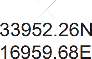
The labels will now resemble Figure 20.25.
Sanity-Saving Settings
In your Civil 3D template, you will have your AutoCAD styles, linetypes, layers, Civil 3D styles, and a plethora of helpful goodies that make doing your job easier. There are a few drawing-specific AutoCAD variables you may not have thought of that will improve your relationship with Civil 3D:
MSLTSCALE
This variable stands for modelspace linetype scale. We strongly recommend that you have this set to 1 in your template. This setting makes linetypes react to your annotation scale. All your other Civil 3D objects are doing it, so having your linetypes follow suit will help! A general rule of thumb is that MSLTSCALE, PSLTSCALE, and LTSCALE should be set to 1. For more information on what these control, check out the Help system.
LAYEREVALCTL
Set this to 0 to avoid the annoying pop-up that flags users when there are new layers in a drawing. Civil drafters are constantly using XRefs and inserting blocks, both of which cause the pop-up to occur.
GEOMARKERVISIBILITY
This is the control for that weird thing in your drawing that appears any time a coordinate system is set up on your drawing. The geomarker looks like a block, but you can't select it and it keeps rescaling as you zoom. Set the GEOMARKERVISIBILITY variable to 0 in your template and the geomarker won't appear. Be aware that if you set it to 0, the option for Locate Using Geographic Data will not be available in XRef and block insert commands.
AUNITS
This variable defines the angular units for the base AutoCAD part of the world. Keep this set at 0 (decimal degrees) to help differentiate base AutoCAD angular entry from Civil 3D angular entry.
Line and Curve Labels
Many Civil 3D objects can have a bearing and distance label added to them. Anything from plain lines and polylines, to parcels and alignment tangent segments, can use nearly identical label types.
The examples in the following exercises will use parcels for labeling, but the tools can be applied to all other types of line labels.
Single Segment Labels
In the following exercise, you will create a new line label style that uses default components. You will remove the direction arrow and change the display precision of the direction component.
1. Open the drawing file Line and Curve Labels.dwg (Line and Curve Labels_METRIC.dwg), which you can download from this book's web page.
2. From the Settings tab of Toolspace, choose Parcel ⇒ Label Styles ⇒ Line; right-click Line and select New.
3. On the Information tab, name the style Parcel Segment.
4. On the General tab, set the layer to C-PROP-LINE-TEXT.
Leave all other General tab options at their defaults.
5. On the Layout tab, do the following:
A. Change the active component to Direction Arrow, and click the red X to delete this component.
B. Change the active component to Distance. Enter the Text Component Editor by clicking in the Text Contents area and clicking the ellipsis.
6. Highlight the Segment Length contents on the right by clicking on the text.
All of the text should highlight as a unit.
7. On the left side of the Text Component Editor, change the Precision value to 0.01.
8. Click the arrow to update the text.
9. Click OK to dismiss the Text Component Editor, and click OK to complete the style.
10. Add labels to the parcels by selecting the Annotate tab ⇒ Labels & Tables panel and doing the following:
A. Click Add Labels and set Feature to Parcel.
B. Set the label type to Single Segment.
C. Set Line Label Style to Parcel Segment.
D. Click Add and select several straight segments for labeling.
The completed label will resemble Figure 20.26.
Spanning Segment Labels
Looking at the labels you created in the previous exercise, you may notice that they stop at each parcel vertex. If the back property line is the same bearing, most plats show these as a single label with an overall length rather than many shorter lengths at the same bearing. To label these in Civil 3D, a separate label style is needed.
Spanning labels can be used in both line and curve parcel labels. In the following exercise, you will create line labels that span across multiple parcel segments:
1. Continue working in the drawing Line and Curve Labels.dwg (Line and Curve Labels_METRIC.dwg).
2. From the Settings tab of Toolspace, expand Parcel ⇒ Label Styles ⇒ Line, right-click Parcel Segments, and select Copy.
3. On the Information tab, name the style Spanning Segment.
4. On the Layout tab:
A. Change the active component name to Table Tag.
B. Change the Span Outside Segments setting to True.
5. Change to the Bearing component, and do the following:
A. Change the Span Outside Segments setting to True.
B. Change the active component to Distance.
C. Change the Span Outside Segments setting to True.
6. Click OK to complete the style.
7. Add labels to the parcels using a similar technique you used in the previous exercise. This time use Spanning Segment as the line label style.

When you initially place a spanning label in the drawing, the overall length will not be reported unless the distance portion of the label is on the outside of a row of parcels. You may need to use the Flip Label command to see the spanning option take effect. Your completed label will resemble Figure 20.27.
Curve Labels
In base AutoCAD, creating curve labels is a chore. If you want text to align to curved objects, it is no longer usable as traditional MTEXT. Luckily, Civil 3D gives you the ability to add curved text without compromising the usability.
In the following exercise, you will create a curve label style with a delta symbol and text that curves with the parcel segment:
1. Continue working in the drawing file Line and Curve Labels.dwg (Line and Curve Labels_METRIC.dwg).
2. From the Settings tab of Toolspace, choose Parcel ⇒ Label Styles ⇒ Curve, right-click on Curve, and select New.
3. On the Information tab, rename the style to Delta Length & Radius.
4. On the General tab, set Layer to C-PROP-LINE-TEXT.
5. On the Layout tab, do the following:
A. Change the active component to Distance And Radius.
B. Enter the Text Component Editor.
C. Highlight the Segment Length property on the right and change the precision to 0.01.
D. Click the arrow to update the style.
6. Highlight the Segment Radius property and change the precision to 0.01.
7. Click the arrow to update the text.
8. Delete the comma that appears as static text in the Text Component Editor, and click OK.
9. Click the Create Text Component button and in the resulting window:
A. Rename the new text component to Delta.
B. Change Attachment to Bottom Center.
C. Change the Y offset to 0.025″ (1 mm).
D. Set Allow Curved Text to True.
10. Enter the Text Component Editor, and remove the default label text.
11. Switch to the Format tab, click the Symbol button, and select Other.
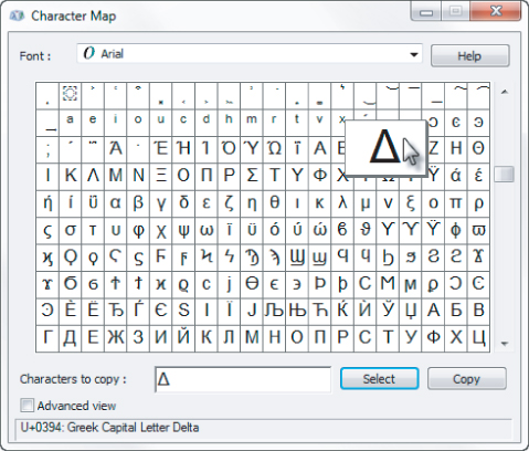
12. Browse through the dialog to find the Delta symbol; when you locate it, click on the symbol, click the Select button, and then click Copy. Click the red X to close the Character Map dialog.
13. Back in the Text Component Editor, click on the right side of the dialog, right-click, and select Paste.
14. Press Backspace on your keyboard if the cursor jumps to the next line of text.
You should now see the delta symbol appear in the Text Component Editor.
15. Type in = as static text after the delta.
16. Switch back to the Properties tab.
17. From the Properties drop-down, select Segment Delta Angle, and do the following:
A. Set the Format to DD°MM′SS.SS″.
B. Set the Precision value to 1 Second.
C. Click the arrow to place the text in the right side.
D. Click OK to exit the Text Component Editor.
18. Click OK to complete the style.
19. Add labels to the parcels using the same technique you used in the previous exercise.
20. Set the active curve label style to Delta Length & Radius.
Your completed label when applied to the design should resemble Figure 20.29.
Pipe and Structure Labels
It seems like no two municipalities label their pipes and sewer structures exactly the same way. Luckily, Civil 3D offers lots of flexibility in how you label these items.
Pipe Labels
Pipe labels have two separate label types: Plan Profile and Crossing Section. Both label types have many of the same options, but are used in different view directions.
In the following exercise, you will use a common “trick” in Civil 3D labels where a nonvisible component acts as an anchor to visible objects. In this case, you will use the flow direction arrow to force text to be placed at the ends and middle of the pipe regardless of the pipe length.
1. Open the drawing file Pipe and Structure Labels.dwg (Pipe and Structure Labels_METRIC.dwg), which you can download from this book's web page.
2. From the Settings tab of Toolspace, choose Pipe ⇒ Label Styles ⇒ Plan Profile, and then right-click Plan Profile and select New.
3. On the Information tab, name the style Length Diameter Slope.
4. On the General tab, set the layer to C-STRM-TEXT.
5. On the Layout tab, delete the existing Pipe Text component.

6. Click the Add New Component button and select Flow Direction Arrow; then adjust these settings:
A. Set Visibility to False.
B. Set Anchor Point to Top Outer Diameter.
C. Set a Y offset of 0.1″ (0.3 mm).
7. Click the Add New Component button and select Text. Change these settings:
A. Rename the Text Component to Length.
B. Set Anchor Component to Flow Direction Arrow.1.
C. Set Anchor Point to Start.
D. Set Attachment to Bottom Left.
E. In the Text Component Editor, remove the default label text.
F. From the Properties list, set 2D Length - Center to Center current.
G. Set Precision to 1 and Rounding to round up. This causes the pipe length value to round to the next highest whole unit.
H. Click the arrow to place the text in the editor.
I. Add a foot symbol (or m for meters) after the text component.
8. Click OK.

9. With Length as the current component, click Copy Component. Then change these settings:
A. Rename the component to Diameter.
B. Change Anchor Point to Middle.
C. Change Attachment to Bottom Center.
D. Enter the Text Component Editor and remove all of the text.
E. From the Properties list, select Inner Pipe Diameter.
F. Set the Precision to 1 and click the arrow to add the text.
G. Add the inch symbol (or mm for millimeters) after the text component.
10. Click OK.
11. With Diameter as the current component, click Copy Component. Then change these settings:
A. Rename the component to Slope.
B. Set Anchor Point to End.
C. Set Attachment to Bottom Right.
D. Enter the Text Component Editor and remove all of the text that is already there. Set Pipe Slope as the current property.
E. Click the arrow to update the text.
12. Click OK.
13. Click OK to complete the style.
14. Add the label to the pipe by doing the following:
A. On the Annotate tab ⇒ Labels & Tables panel, click Add Labels.
B. Set the Feature option to Pipe Network and Label Type to Single Part Plan.
C. Set the pipe label style to Length Diameter Slope and the label style to Current.
D. Click Add. Select any pipe in plan view.
Your labeled pipe will resemble Figure 20.30.
Structure Labels
Structure labels are nifty because they have a component no other label style has: the Text For Each component. The number of pipes entering and exiting a structure will vary depending on where the structure is in a network, and the Text For Each option accommodates that unique feature.

Adding Existing Ground Elevation to Structure Labels
In design situations, it's often desirable to track not only the structure rim elevation at finished grade, but also the elevation at existing ground. This gives the designer an additional tool for optimizing the earthwork balance.
This exercise will lead you through creating a structure label that includes surface-reference text. It assumes you're familiar with Civil 3D label composition in general:
1. Continue working in the file Pipe and Structure Labels.dwg (Pipe and Structure Labels_METRIC.dwg).
2. Locate the Structure Label Styles branch on the Settings tab of Toolspace.
3. Right-click Label Styles and select New, and then do the following:
A. On the Information tab, name the label Structure w Surface.
B. On the General tab, set the layer to C-STRM-TEXT.
C. On the Layout tab is a default text component called Structure Text. Set the Y offset to -0.25″ (-1 mm).
D. Click in the Contents box to bring up the Text Component Editor.
E. Delete the <[Description(CP)]> text string.
F. Set the Properties drop-down menu to <Name> and click the arrow button.
G. Press

to move to the next line and type
RIM with a space after it.
H. Set the Properties drop-down to <Insertion Rim Elevation>, set the Precision to two decimal places and click the arrow button.
4. Click OK to leave the Text Component Editor.
5. In the Label Style Composer, choose Reference Text from the Add Component drop- down menu.
6. In the Select Type dialog, choose Surface, and then click OK.
7. Rename the component from Reference Text.1 to Existing Ground.
8. Click in the Contents box, and then click the ellipsis to bring up the Text Component Editor.
9. Delete the Label Text text string, and then use the Properties drop-down menu to add the EG and a space <Surface Elevation> (two decimal places). Click the arrow to add the surface information to the label.
10. Click OK to dismiss the Text Component Editor.
11. In the Label Style Composer, do the following:
A. Change Anchor Component For Existing Ground to Structure Text.
B. Change Anchor Point to Bottom Center.
C. Change Attachment to Top Center.
12. Choose the Text For Each option from the Add Component drop-down menu.
13. In the Select Type dialog, choose Structure All Pipes, and then click OK.
14. Click in the Contents box, and then click the ellipsis to bring up the Text Component Editor.
15. Delete the Label Text text string, and then use the Properties drop-down menu to add the INV and a space <Connected Pipe Invert Elevation> (two decimal places). Click the arrow to add the surface information to the label.
16. Click OK to dismiss the Text Component Editor.
17. In the Label Style Composer, do the following:
A. Change Anchor Component For Text for Each.1 to Existing Ground.
B. Change Anchor Point to Bottom Center.
C. Change Attachment to Top Center.
18. Click OK to dismiss the Label Style Composer.
19. Select the Annotate tab ⇒ Labels & Tables panel and click Add Labels.
A. Set the Feature option to Pipe Network.
B. Set the label type to Single Part Plan.
C. Set the structure label style to Structure w Surface.
D. Click Add.
20. Click the structure you want to label.
You will immediately see a prompt at the command line that reads Select surface for label style component Existing Ground Surface:.
21. Press

to select EG from the surface listing and then click OK.
Your label is now complete.
Profile and Alignment Labels
Profile and alignment labels can take on many forms. On an alignment you may want to show labels every 100′ (25 m) in addition to PC, PT, and PI information. On a profile, you will want tangent grades, curve information, and grade breaks.
For every element you wish to label, a separate style controls the look and behavior of that label.
Label Sets
A label set is a grouping of labels that apply to the same object. In lieu of having one big style that accounts for multiple aspects of an object, the labels are broken out into specific pieces to allow you more control.
Label sets come into play with alignments and design profiles. When you look at an alignment or profile and see labels, you are usually seeing multiple label styles in action.
Consider the alignment shown in Figure 20.31. How many labels are there on this alignment? The geometry points, the major ticks, the minor ticks, superelevation stations, and design speed are all separate labels.
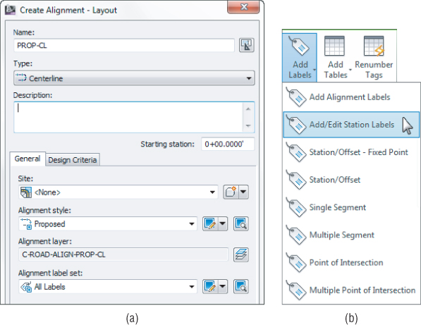
How did those labels get here? When you first created the alignment or profile, one of the options was to specify a label set (as shown in Figure 20.32a). The labels from the set are applied as a batch to the object.
To edit which labels are applied to an alignment or profile, select Add/Edit Station Labels from the context tab (as shown in Figure 20.32b).
Label sets also dictate the placement of the annotation. An alignment label set controls the major and minor station labeling increment. A profile label set has a big job to do in helping you place labels in the correct location with respect to both the design and the profile view. In Figure 20.33, Dim Anchor Opt and Dim Anchor Val control where the label is placed on the object, or in relation to the graph.
Alignment Labels
You'll create individual label styles over the next couple of exercises and then pull them together with a label set. At the end of this section, you'll apply your new label set to the alignments.
Major Station
Major station labels typically include a tick mark and a station callout. In this exercise, you'll build a style to show only the station increment and run it parallel to the alignment:
1. Open the Alignment&ProfileLabels.dwg (Alignment&ProfileLabels_METRIC.dwg) file, which you can download from this book's web page.
2. Switch to the Settings tab, and expand the Alignment ⇒ Label Styles ⇒ Station ⇒ Major Station branch.
3. Right-click the Parallel With Tick style and select Copy.
The Label Style Composer dialog appears.
4. On the Information tab, type Index Station in the Name field.
5. Switch to the Layout tab.
6. Click in the Contents Value field, under the Text property, and then click the ellipsis button to open the Text Component Editor dialog.
7. Click in the preview area, and delete the text that's already there.
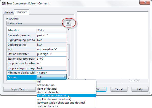
8. With station Value as the active property, click in the Output Value field, and click the down arrow to open the drop-down list.
You will need to scroll down to see the Output option.
9. Select the Left Of Station Character option, as shown in
Figure 20.34, and click the insert arrow circled in the figure. (Metric users, the resulting label will be more interesting if you use the Right Of Station Character option instead. Because this alignment is less than 300 m, the left option will give you all 0s!)
10. Click OK to close the Text Component Editor dialog.
11. Click OK to close the Label Style Composer dialog.
The label style now shows in your label styles, but it's not applied to any alignments yet.
Geometry Points
Geometry points reflect the PC, PT, and other points along the alignment that define the geometric properties. The existing label style doesn't reflect a plan-readable format, so you'll copy it and make a minor change in this exercise:
1. Continue working in the Alignment&ProfileLabels.dwg (Alignment&ProfileLabels_METRIC.dwg) file.
2. Expand the Alignment ⇒ Label Styles ⇒ Station ⇒ Geometry Point branch.
3. Right-click the Perpendicular With Tick style, and select Copy to open the Label Style Composer dialog.
4. On the Information tab, change the name to Perpendicular with Line.
5. Switch to the General tab.
6. Change the Readability Bias setting to 90.
This value will force the labels to flip at a much earlier point.
7. Switch to the Layout tab and make these changes:
A. Set the Component Name field to the Tick option.
B. Click the Delete Component button (the red X button).

C. Click the Create New Line Component button.
D. Change the Line Angle to 90.
E. Change the component to Geometry Point & Station.
F. Change the Anchor Component to Line.1.
G. Change the Anchor Point to End.
H. Change Rotation Angle to 0.
8. Click OK.
9. Click OK to close the Label Style Composer dialog.
10. Save the drawing.
This new style flips the plan-readable labels sooner and includes a line with the label. Next, you will put the styles together in a set.
Alignment Label Set
Once you have several labels you wish to use on an alignment, it is time to save them as an alignment label set.
1. Continue working in Alignment&ProfileLabels.dwg (Alignment&ProfileLabels_METRIC.dwg). On the Settings tab of Toolspace, expand the Alignment ⇒ Label Styles ⇒ Label Sets branch.
2. Right-click Label Sets, and select New to open the Alignment Label Set dialog.
3. On the Information tab, change the name to Paving.
4. Switch to the Labels tab.
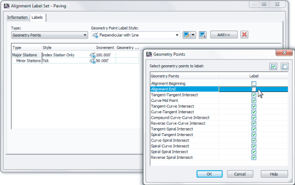
5. Set the Type field to the Major Stations option and the Major Station Label Style field to the Index Station Only style that you just created; then click the Add button.
6. Set the Type field to the Minor Stations option and the Minor Station Label Style field to the Tick option; then click the Add button.
7. Set the Type field to Geometry Points and the Geometry Point Label Style field to Perpendicular With Line. Then click the Add button to open the Geometry Points dialog, as shown
Figure 20.35.
8. Deselect the Alignment Beginning and Alignment End check boxes as shown, and then click OK to dismiss the dialog.
Three label types will now be shown in the Alignment Label Set dialog.
9. Click OK to dismiss this dialog.
In the next exercise, you'll apply your label set to the example alignment and then see how an individual label can be changed from the set.
1. Continue working in the Alignment&ProfileLabels.dwg (Alignment&ProfileLabels_METRIC.dwg) file. Select the Example alignment on screen.
2. Right-click, and select Edit Alignment Labels to display the Alignment Labels dialog.
This dialog shows which labels are currently applied to the alignment. Initially, it will be empty.
3. Click the Import Label Set button near the bottom of this dialog.
Any labels appearing in this listing will be replaced by the labels in the set that is imported.
4. In the Select Style Set drop-down list, select the Paving Label Set and click OK.
The alignment labels list populates with the option you selected.
5. Click OK to dismiss the dialog.
6. When you've finished, press Esc twice to be sure you have exited the command and zoom in on any of the major station labels.
7. Hold down the Ctrl key, and select one of the major station labels.
Notice that a single label is selected, not the label set group.
8. Now that the single label is selected, drag the grip to leader it off.
9. Right-click and select Label Properties.
The Label Properties dialog appears, allowing you to pick another label style from the Major Station Label Style drop-down list.
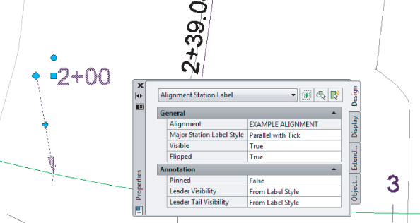
10. Change the Label Style value to Parallel With Tick, and change the Flip Label value to True, as shown in
Figure 20.36.
11. Press Esc to deselect the label item.
If you add labels to an alignment and like the look of the set, use the Save Label Set option. By using alignment label sets, you'll find it easy to standardize the appearance of labeling and stationing across alignments. Building label sets can take some time, but it's an easy, effective way to enforce standards.
Station Offset Labeling
Beyond labeling an alignment's basic stationing and geometry points, you may want to label points of interest in reference to the alignment. Station offset labeling is designed to do just that. In addition to labeling the alignment's properties, you can include references to other object types in your station-offset labels. The objects available for referencing are as follows:
- Other alignments
- COGO points
- Parcels
- Profiles
- Surfaces
In Chapter 11, “Advanced Corridors, Intersections, and Roundabouts,” you used special alignment labels that referenced other alignments to make adjusting your design easier. In this exercise, you will make a similar type of label. The label you create in the following exercise finds the intersection of two alignments.
1. Open the Alignment&ProfileLabels.dwg (Alignment&ProfileLabels_METRIC.dwg) drawing file.
2. On the Settings tab, expand Alignment ⇒ Label Styles ⇒ Station Offset.
3. Right-click Station And Offset, and select Copy to open the Label Style Composer dialog.
4. On the Information tab, change the name of your new style to Alignment Intersection.
5. Switch to the Layout tab. In the Component Name field, delete the Marker component.
6. In the Component Name field, select the Station Offset component.
7. Change the name to Main Alignment.
8. In the Contents Value field, click the ellipsis button to bring up the Text Component Editor.
9. Select the text in the preview area and delete it all.
10. Type Sta. in the preview area; be sure to leave a space after the period.
11. In the Properties drop-down field, select Station Value, and set the Precision to 0.01.

12. Click the insert arrow in the Text Component Editor dialog; press the right arrow on your keyboard to move your cursor to the end of the line, and type one space.
13. In the Properties drop-down field, select Alignment Name.
14. Click the insert arrow to add this bit of code to the preview.
15. Click your mouse in the preview area, or press the right arrow or End key. Move to the end of the line, and type a space and an equal sign (=).
16. Click OK to return to the Label Style Composer dialog.
17. Under the Border Property, set the Visibility field to False.

18. Select Reference Text from the drop-down list next to the Add Component tool.
19. In the Select Type dialog that appears, select Alignment and click OK.
20. Change the name to Intersecting Alignment.
21. In the Anchor Component field, select Main Alignment.
22. In the Anchor Point field, select Bottom Left.
23. In the Attachment field, select Top Left.
When you choose the anchor point and attachment point in this fashion, the bottom left of the Main Alignment text is linked to the top left of the Intersection Alignment text.
24. Click in the Contents field, and click the ellipsis button to open the Text Component Editor.
25. Delete the generic label text that currently appears in the preview area.
26. Type Sta. in the preview area; be sure to leave a space after the period.
27. In the Properties drop-down list, select Station Value.
28. Click the insert arrow in the Text Component Editor dialog, and then move your cursor using the right arrow on your keyboard or End key, and add a space.
29. In the Properties drop-down list, select Alignment Name.
30. Click the insert arrow to add this bit of code to the preview.
31. Click OK to exit the Text Component Editor, and click OK again to exit the Label Style Composer dialog.
32. Add the label to the drawing by selecting the Annotate tab and clicking Add Labels.
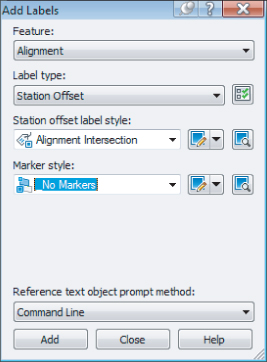
33. Change the label settings to match those shown in
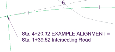
Figure 20.38 and click Add.
Watch the command line for placement instructions. You will be prompted to select the main alignment, the station along the alignment, and the offset. You will then be prompted to click the intersecting alignment.
34. Press Esc to complete the labeling command.
35. Click the label to select it and reveal the grips. Select the square grip and drag it away from the current location to form a leader.
Your completed label should look like Figure 20.39.
Profile Labels
It's important to remember that the profile and the profile view aren't the same thing. The labels discussed in this section are those that relate directly to the profile. This usually means station-based labels, individual tangent and curve labels, or grade breaks. You'll look at individual label styles for these components and then at the concept of the label set.
Profile Label Sets
As with alignments, you apply labels as a group of objects separate from the profile in the form of profile label sets. In this exercise, you'll learn how to add labels along a profile object:
1. Open the Alignment&ProfileLabels.dwg (Alignment&ProfileLabels_METRIC.dwg) file.

2. Pick the blue layout profile (the profile with two vertical curves) to activate the profile object.
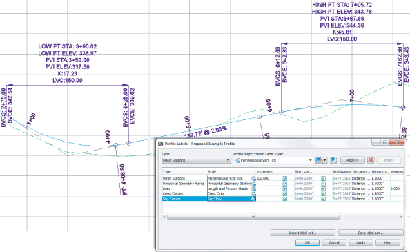
3. From the Profile contextual tab ⇒ Labels panel, select Edit Profile Labels to display the Profile Labels dialog (see
Figure 20.40).
Selecting the type of label from the Type drop-down menu changes the Style drop-down menu to include styles that are available for that label type. Next to the Style drop-down menu are the usual Style Edit/Copy button and a preview button. Once you've selected a style from the Style drop-down menu, clicking the Add button places it on the profile. The middle portion of this dialog displays information about the labels that are being applied to the profile selected; you'll look at that in a moment.
4. Choose the Major Stations option from the Type drop-down menu.
The name of the second drop-down menu changes to Profile Major Station Label Style to reflect this option.
5. Set the style to Perpendicular With Tick in this menu.
6. Click Add to apply this label to the profile.
7. Choose Horizontal Geometry Points from the Type drop-down menu.
The name of the Style drop-down menu changes to Profile Horizontal Geometry Point.
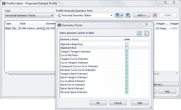
8. Select the Horizontal Geometry Station style, and click Add again to display the Geometry Points dialog shown in
Figure 20.41.
This dialog lets you apply different label styles to different geometry points if necessary.
9. Deselect the Alignment Beginning and Alignment End rows, as shown in
Figure 20.41, and click OK to close the dialog.
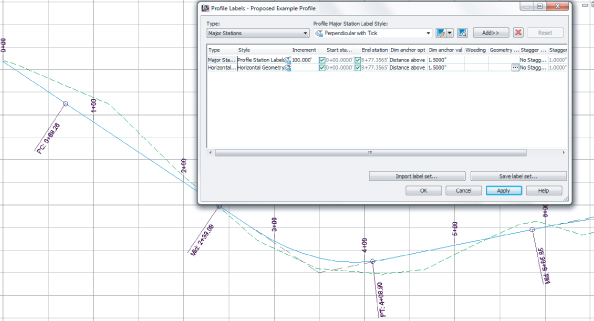
10. Click the Apply button, and then drag the dialog out of the way to view the changes to the profile (see
Figure 20.42).
11. In the middle of the Profile Labels dialog, change the Increment value in the Major Stations row to
50′ (
20 m), as shown in
Figure 20.43.
This modifies the labeling increment only, not the grid or other values.
12. Click OK to close the Profile Labels dialog.
As you can see, applying labels one at a time could turn into a tedious task. After you learn about the types of labels available, you'll revisit this dialog and look at the two buttons at the bottom for dealing with label sets.
Line Labels
Line labels in profiles are typically used to convey the slope or length of a tangent segment. In this exercise, you'll add a length and slope to the layout profile:
1. Continue working in the Alignment&ProfileLabels.dwg (Alignment&ProfileLabels_METRIC.dwg) file.
2. Switch to the Settings tab of Toolspace.
3. Expand the Profile ⇒ Label Styles ⇒ Line branch.
4. Right-click Percent Grade, and select the New option to open the Label Style Composer dialog and create a child style.
5. On the Information tab, change the name to Length and Percent Grade.
6. Switch to the Layout tab and make these changes:
- Change Attachment to Top Center.
- Set the Y-offset to -0.025″ (-1 mm).
- Set Background Mask to True.
7. Click in the cell for the Contents value, and click the ellipsis button to display the Text Component Editor.
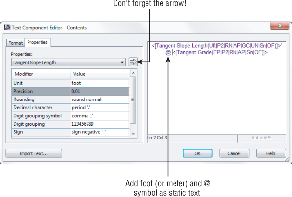
8. Change the Properties drop-down menu to the Tangent Slope Length option and the Precision value to
0.01, as shown in
Figure 20.44.
9. Put your cursor at the beginning of the existing text in the preview windows, click the insert arrow, and then add a foot (or
m for meter) symbol, a space, an
@ symbol, and another space in the editor's preview pane so that it looks like
Figure 20.44.
10. Click OK to close the Text Component Editor, and click OK again to close the Label Style Composer dialog.
11. Pick the layout profile. From the Profile contextual tab ⇒ Labels panel, select Edit Profile Labels from the Labels panel to display the Profile Labels dialog.
12. Change the Type field to the Lines option. The name of the Style drop-down menu changes to Profile Tangent Label Style. Select the Length And Percent Grade option.
13. Click the Add button, and then click OK to exit the dialog. The profile view should look like
Figure 20.45.
Where Is That Distance Being Measured?
The tangent slope length is the distance along the horizontal geometry between vertical curves. This value doesn't include the tangent extensions. There are a number of ways to label this length; be sure to look in the Text Component Editor if you want a different measurement.
Curve Labels
Vertical curve labels are one of the most confusing aspects of profile labeling. Many people become overwhelmed rapidly, because there's so much that can be labeled and there are so many ways to get all the right information in the right place. In this quick exercise, you'll look at some of the special label anchor points that are unique to curve labels and how they can be helpful:
1. Open the Alignment&ProfileLabels.dwg (Alignment&ProfileLabels_METRIC.dwg) file.
2. Pick the layout profile. From the Profile contextual tab ⇒ Labels panel, select Edit Profile Labels to display the Profile Labels dialog.
3. Choose the Crest Curves option from the Type drop-down menu.
The name of the Style drop-down menu changes.
4. Select the Crest Only option.
5. Click the Add button to apply the label.
6. Choose the Sag Curves option from the Type drop-down menu.
The name of the Style drop-down menu changes to Profile Sag Curve Label Style.
7. Select and add the Sag Only label style. Click the Add button to apply the label.
8. Click OK to close the dialog.
Your profile should look like Figure 20.46.
Most labels are applied directly on top of the object being referenced. Because typical curve labels contain a large amount of information, putting the label right on the object can yield undesired results. In the following exercise, you'll modify the label settings to review the options available for curve labels:
1. Continue working in the Alignment&ProfileLabels.dwg (Alignment&ProfileLabels_METRIC.dwg) file.
2. Pick the layout profile and select Edit Profile Labels from the Labels panel to display the Profile Labels dialog.
3. Scroll to the right, and change both Dim Anchor Opt values for the Crest and Sag Curves to Graph View Top.
4. Change the Dim Anchor Val for both curves to -2.25″ (-10 mm), and click OK to close the dialog.
Your drawing should look like Figure 20.47.
The labels can also be grip-modified to move higher or lower as needed. By using the top or bottom of the graph as the anchor point, you can apply consistent and easy labeling to the curve, regardless of the curve location or size.
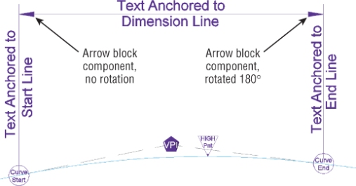
Those Crazy Curve Labels!
A profile curve label can be as intricate or simple as you desire. Civil 3D gives you many options for where along the curve feature you want your label component to appear. The following illustration shows where some of the commonly used curve locations are in a label:
Grade Breaks
The last label style typically involved in a profile is a grade-break label at PVI points that don't fall inside a vertical curve, such as the beginning or end of the layout profile. Additional uses include things like water-level profiling, where vertical curves aren't part of the profile information or existing surface labeling. In this exercise, you'll add a grade-break label and look at another option for controlling how often labels are applied to profile data:
1. Open the Alignment&ProfileLabels.dwg (Alignment&ProfileLabels_METRIC.dwg) file.
2. Pick the green surface profile (the irregular profile). From the Profile contextual tab ⇒ Labels panel, select Edit Profile Labels to display the Profile Labels dialog.
3. Choose Grade Breaks from the Type drop-down menu.
The name of the Style drop-down menu changes.
4. Select the Station Over Elevation style and click the Add button.
5. Click Apply, and drag the dialog out of the way to review the change.
A sampled surface profile has grade breaks every time the alignment crosses a surface TIN line. Why wasn't your view coated with labels?
6. Scroll to the right, and change the Weeding value to 150′ (45 m). Click Apply.
7. Select one of the new grade break labels. Use the square grip at the location where the label touches the profile to form a leader and clean up any labels that overlap.
8. Click OK to dismiss the dialog.
Weeding lets you control how frequently grade-break labels are applied. This makes it possible to label dense profiles, such as a surface sampling, without being overwhelmed or cluttering the view beyond usefulness.
As you've seen, there are many ways to apply labeling to profiles, and applying these labels to each profile individually could be tedious. In the next section, you'll build a label set to make this process more efficient.
Profile Label Sets
Applying labels to both crest and sag curves, tangents, grade breaks, and geometry with the label style selection and various options can be monotonous. Thankfully, Civil 3D gives you the ability to use label sets, as in alignments, to make the process quick and easy. In this exercise, you'll apply a label set, make a few changes, and export a new label set that can be shared with team members or imported to the Civil 3D template. Follow these steps:
1. Open the Alignment&ProfileLabels.dwg (Alignment&ProfileLabels_METRIC.dwg) file.
2. To tidy things up, select one of the grade-break labels from the previous exercise. Press Delete on your keyboard to remove the labels.
3. Pick the layout profile. From the Profile contextual tab ⇒ Labels panel, select Edit Profile Labels to display the Profile Labels dialog.
4. Click the Import Label Set button near the bottom of the dialog to display the Select Style Set dialog.
5. Select the Complete Label Set option from the drop-down menu, and click OK.
6. Click OK again to close the Profile Labels dialog and see the profile view.
The label set you chose contains curve labels, grade-break labels, and line labels.
7. Pick the layout profile. From the Profile contextual tab ⇒ Labels panel, select Edit Profile Labels to display the Profile Labels dialog.
8. Click Import Label Set to display the Select Style Set dialog.
9. Select the _No Labels option from the drop-down menu, and click OK.
All the labels from the listing will be removed.
In the next steps, you will add labels to the listing and save the listing as its own label set for future use.
10. Set the active type to Lines. Set Profile Tangent Label Style to Length And Percent Grade, and click Add.
11. Set the active type to Grade Breaks. Set Profile Grade Break Label Style to Station Over Elevation, and click Add.
12. Set the type to Crest Curves. Set Profile Crest Curve Label Style to Crest Only, and click Add.
13. Set the type to Sag Curves. Set Profile Sag Curve Label Style to Sag Only, and click Add.
14. Set the Crest Curve and Sag Curve label types to use the Graph View Top as the Dim Anchor Opt.
15. Set both Dim Anchor Val fields to
-1.5″ (
-40 mm), as shown in
Figure 20.49.
16. Click the Save Label Set button to open the Profile Label Set dialog and create a new profile label set.
17. On the Information tab, change the name to Road Profile Labels.
18. Click OK to close the Profile Label Set dialog.
19. Click OK to close the Profile Labels dialog.
20. On the Settings tab of Toolspace, select Profile ⇒ Label Styles ⇒ Label Sets.
Note that the Road Profile Labels set is now available for sharing or importing to other profile label dialogs.
Label sets are the best way to apply profile labeling uniformly. When you're working with a well-developed set of styles and label sets, it's quick and easy to go from sketched profile layout to plan-ready output.
Advanced Style Types
Now that you are familiar with the basics of object styles and label styles, you are ready to take your skills to the next level. The styles in the following section combine aspects of object styles and label styles.
You have a great deal of control over every detail, even ones that may seem trivial. Instead of being bogged down trying to understand every option, don't be afraid to try a “trial and error” approach. If you make a change you don't like, you can always edit the style until you get it right.
Table Styles
Civil 3D does a beautiful job of placing dynamically-linked data tables that relate to your objects. The tables use the Text Component Editor to grab dynamic information from your objects. You also have control over fill colors, table headings, and how the data is sorted.
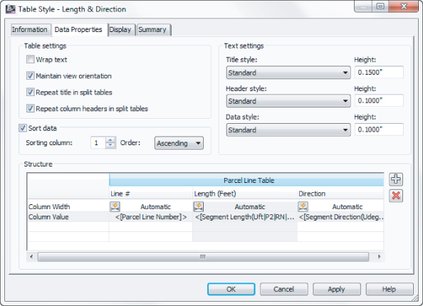
For the table style, the Data Properties tab contains all the column information. You can add columns by clicking the plus sign. You can remove columns by highlighting the column you want to remove and clicking the Delete button. Change column order by dragging them around and dropping them where you want them to go, as shown in Figure 20.50.
In the following exercise you will see the basic steps of modifying a table style. Now that you understand the ins and outs of the Label Style Composer, this procedure should be a breeze:
1. Open the Tables.dwg (Tables_METRIC.dwg) file, which you can download from this book's web page.
This file contains a parcel line table whose style you will modify.
2. Zoom into the parcel line table.
Notice there are several things you will want to change:
- The line numbers are out of order.
- The directions have far too much precision.
- The length does not display units.
All that is about to change.

3. Click the table to select it. From the context tab, select the Table Properties drop-down and choose Edit Table Style.
4. Switch to the Data Properties tab.
The Data Properties tab (
Figure 20.51) is the main control area for all table styles. This is where you set behavior, text styles, and sizes for fields.
5. Place a check mark next to Sort Data, and set the Sorting column to 1.
Column 1 corresponds to the Column Value containing the Parcel Line Number. Set the order option to Ascending. The Ascending option will ensure that the parcel numbers are listed in the table from the lowest to highest value.
6. Double-click the column heading field for Length.
Doing so opens a stripped-down version of the Text Component Editor. Headings and table titles are static text only; therefore only the text formatting tools are shown.
7. Add
(Feet) ((meters)) after the column heading to add a proper units heading to the column, as shown in
Figure 20.52, and click OK.
8. Double-click the Direction Column value field below the column heading.
Doing so opens the Text Component Editor, similar to what you've used in earlier exercises.
9. Click on the text in the preview area so that it becomes highlighted.
10. Change Precision to 1 Second.
11. Click the arrow to update the text. Click OK.
12. Click OK to complete the table style modifications.
Code Set Styles
Code set styles determine how your assembly design will appear. Code set styles are used in many places. A code set style is in play when you first create your assembly. One is used in corridor creation and in the Section Editor. The most apparent use of a code set style is in section views like those that you created in the previous exercise.
Code set styles are a collection of many other styles. In a code set style you will find:
- Links and link label styles
- Points, point label styles, and feature line styles
- Shapes and shape label styles
- Quantity takeoff pay items
- Render materials for visualization tasks
It is helpful in naming your code set style to have the name of the set reflect its use. Multiple code set styles are needed because of different applications of its use. When you are designing an assembly, you may want to see more labels than when you are getting ready to plot the assembly in a cross-section sheet. Labeling that is useful in a cross-section sheet may obstruct your view of the design when working with it in the corridor cross-section editor.
The hardest part of working with code set styles is figuring out the name of the link or point you wish to label. Luckily, it is unusual for users to label shapes, so you won't need to worry about those. The names of each point or link can be found in the subassembly properties. Most of the links and points are logically named, but there's no harm in a little trial and error if you are not sure.
Shapes
Shapes are the areas that define materials. Because it is not common for people to label these materials in a section view, you will not be experiencing these in an exercise.
One heads-up, however: Resist the temptation to use a hatch pattern on shapes where multiple cross-section views will be created. Solid fills and no patterns are your best bet to avoid performance issues and the annoying “Hatch pattern is too dense” warning.
Links and Link Labels
You learned in Chapter 8, “Assemblies and Subassemblies,” that a link is the linear part of a subassembly. The object style for the link itself is very simple—just a single linear component. The label for a link is usually expressed as a percent grade or as a slope ratio.
In the following exercise, you will modify a code set style to apply link labels to an assembly.
1. Open the Code Set Styles.dwg (Code Set Styles_METRIC.dwg) file, which you can download from this book's web page.
This file contains a corridor and cross-section views. Zoom into one of the cross-section views so you can observe the changes as you apply them to the code set style.
2. From the Settings tab of Toolspace, expand General ⇒ Multipurpose Styles ⇒ Code Set Styles; right-click on All Codes, and select Edit.
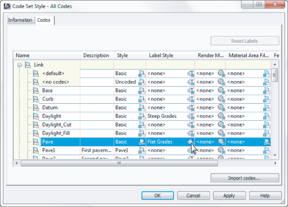
3. In the Codes tab Link list, locate Pave, and click the Label Tag icon in the Label Style column, as shown in
Figure 20.53.
4. Select the Flat Grades label style and click OK; then click Apply to examine the change on the cross sections.
You should see that the lanes now have slope information labeled.
5. In the Link list, locate Daylight; click the Label Tag icon in the Label Style column, and select Steep Grades as the label style.
6. Click OK, and then click OK to dismiss the All Codes label style and see what is happening with the cross section.
The cross sections should resemble Figure 20.54.
It's Just an Expression
Expressions allow you to use properties available in a label and perform calculations. The resulting expression can then be used as part of a displayed label, or as any of the numerical text settings such as text height, rotation angle, or width.
A frequently seen use of expressions is with surface spot elevations. In the following image, an expression called Slant Curb contains {Surface Elevation}-0.125. The label style then uses the Slant Curb as one of the properties displayed in the spot elevation label as shown here:
Another common use of expressions is in code set styles. You want to label all of the Top codes, but on short segments the labels would appear too crowded.
In the following example, an expression is used as the text height in a code set style. When the length of the link is large enough, the text appears normally. If the link is shorter than 0.5′ (0.1 m), the text is set to a value that makes it too small to see.
1. Open the drawing Expression.dwg (Expression_METRIC.dwg).
2. Zoom into one of the cross-sections views.
You will see that the labels are crowded on the assembly. An expression can help clean this up by omitting labels for segments that are too short.
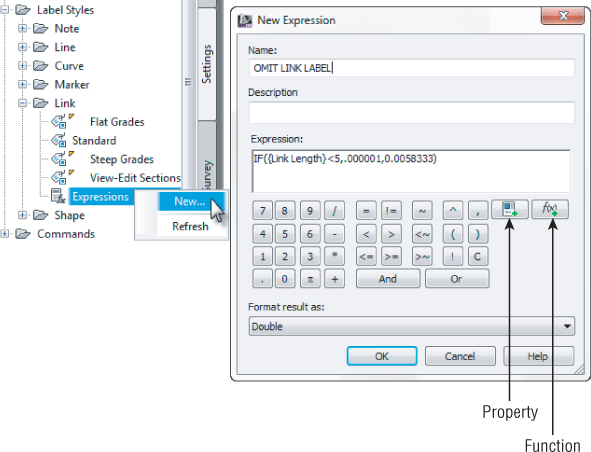
3. In the Settings tab of Toolspace ⇒ General ⇒ Label Styles ⇒ Link, right-click Expressions and select New.
4. Name the expression OMIT LINK LABEL.
5. Click the function button to the right and select IF.
A peek into the Civil 3D Help will tell you what it is expecting after the IF. According to help, the syntax is IF(test,true_val,false_val). The “test” in this example is if the link is less than 5′ (1.5 m). If the link is less than the desired length, the text size will be very small so that it is effectively hidden. If the link is the desired length or longer, then a text height of 0.005833′ (0.002 m) will be used.
6. Click the Property button and select Link Length.
7. Enter a < sign or click the < operator button in the New Expression dialog.
8. Enter 5′ (1.5 m) and the test portion of the expression is complete.
9. Add a comma and add 0.000001′ (0.0000001 m).
This is the extremely small text height that will hide the text. The units are only shown in these examples to distinguish unit systems; do not add them to the expression.
10. Add another comma and add 0.0058333′ (0.0015 m).
This is the text height that will display. Note that the value is in feet (or meters).
11. Add a close parenthesis and verify that Format Result As is set to Double.
12. When your new expression resembles the following image, click OK.
13. In the same branch of Prospector, right-click Flat Grades and select Edit.
14. On the Layout tab of the Label Style Composer, click in the text height field and set it to OMIT LINK LABEL. Click OK.
15. Run REGEN on your drawing if you don't see the change right away.
The labels on the section should now look much neater.
Points and Point Labels
A common frustration with new users of Civil 3D are the marker styles and their labels. For display in cross-section views, you may not want points to display at all. In the following exercise, you will create a new code set style, modify point codes, and add more labels to the sections:
1. Continue working in Code Set Styles.dwg (Code Set Styles_METRIC.dwg).
2. From the Settings tab of Toolspace, expand General ⇒ Multipurpose Styles Code Set Styles. Right-click on All Codes and select Copy.
3. On the Information tab, rename the style to All Codes-Plotting.
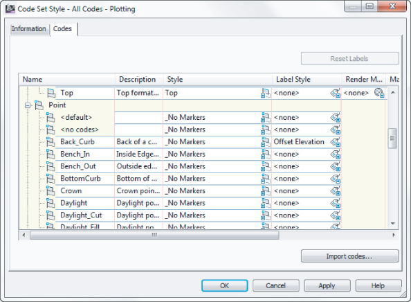
4. On the Codes tab, locate the Point category. Locate the Back_Curb point and click the Tag icon in the Label Style column. Set the style to Offset Elevation. Click OK.
5. Repeat step 4 to set the label style for Sidewalk_Out to Offset Elevation.
6. Click the first point name, <default>. While holding down the Shift key on your keyboard, scroll down to the last point listing, Top_Curb. With all of the points selected, click the Tag icon in the style column and change the style to _No Markers. Click OK.
7. Click OK.
You do not see any changes to your cross sections yet because the style is not active.
8. Select a section view. From the Section Views contextual tab ⇒ Modify View panel, select View Group Properties.
9. On the Sections tab, change the style of the EXAMPLE corridor to the All Codes-Plotting style you created, as shown in
Figure 20.56, and click OK.
10. Click OK again to complete the changes to the Section View Group Properties dialog.
Your section view should now resemble Figure 20.57.
The Bottom Line
Override individual labels with other styles.
In spite of the desire to have uniform labeling styles and appearances between alignments within a single drawing, project, or firm, there are always exceptions. Using the Ctrl+click method for element selection, you can access commands that let you modify your labels and even change their styles.
Master It
Open the drawing MasteringLabelStyles.dwg (MasteringLabelStyles_METRIC.dwg). Create a copy of the Perpendicular With Tick Major Station style called Major With Marker. Change Tick Block Name to Marker Pnt. Replace some (but not all) of your major station labels with this new style.
Create a new label set for alignments.
Label sets let you determine the appearance of an alignment's labels and quickly standardize that appearance across all objects of the same nature. By creating sets that reflect their intended use, you can make it easy for a designer to quickly label alignments according to specifications with little understanding of the requirement.
Master It
Within the Mastering LabelStyles.dwg (Mastering Label Styles_METRIC.dwg) file, create a new label set containing only major station labels, and apply it to all the alignments in that drawing.
Create and use expressions.
Expressions give you the ability to add calculated information to labels or add logic to label creation.
Master It
In the Mastering LabelStyles.dwg (Mastering Label Styles_METRIC.dwg file, create an expression that adds 0.5¢ (0.15 m) to a surface elevation. Use the expression in a spot elevation label that shows both the surface elevation and the expression-based elevation.
Apply a standard label set to profiles.
Standardization of appearance is one of the major benefits of using Civil 3D styles in labeling. By applying label sets, you can quickly create plot-ready profile views that have the required information for review.
Master It
In the Mastering LabelStyles.dwg (Mastering Label Styles_METRIC.dwg) file, apply the Road Profiles label set to all layout profiles.
![]()





![]()

![]()
![]()
![]()

![]()



![]()


![]()



![]()



![]()

![]()



![]()
![]()

![]()







![]()
