Chapter 18
Advanced Workflows
The AutoCAD® Civil 3D® program is unique in that with a few exceptions, the data you create is stored in the DWG. Using data shortcuts will allow you to collaborate with coworkers and prevent the DWG size from getting unwieldy. Even if you work on small projects, data shortcuts can make creating cross-section views a more straightforward process.
As survey technology advances and sources for accurate data become more varied, the ability to transform between coordinate systems and collaborate with other versions of software is imperative. For the solutions to many interoperability questions, you will look to LandXML and the Map functionality to help you along.
In this chapter, you will learn to:
- Create a data shortcut folder
- Create data shortcuts
- Export to earlier releases of AutoCAD
- Export to LandXML
- Transform coordinates between drawings
Data Shortcuts

A data shortcut is a link between drawings, allowing specific types of Civil 3D data to be shared. The shortcut itself does not contain data, but it is a pointer, directing Civil 3D to read data from a common pool of data. A data shortcut is created in the source drawing and a data reference is the manifestation of the data in a host drawing.
There are many situations in which you need data or information to link between drawings. Connections between drawings can be in the form of external references (XREFs), data shortcuts, or a combination of the two. These two options are similar but not the same. Let's compare (Table 18.1).
Table 18.1 XREF vs. data shortcut
| For most objects, XREF is a graphic-only representation of objects created in another drawing. |
Information-only link to Civil 3D data created in another DWG. |
| Any objects (base AutoCAD or Civil 3D) are displayed in XREFs. |
Only specific types of Civil 3D data can be used with data shortcuts. |
| Visibility of objects controlled by original drawing layers. |
Visibility of data controlled by host drawing styles and layers. |
| A drawing containing a Civil 3D surface or parcels can be XREF'ed into a host drawing and labeled dynamically. |
Surface data must be referenced using a data shortcut for use in design (i.e., creating an existing ground profile) |
| A drawing containing a Civil 3D corridor can be XREF'ed into a host drawing. Sample lines can pull corridor data from the XREF. |
A data shortcut to an alignment in conjunction with an XREF to the corridor enables sample lines to be created in a separate drawing. |
As noted, only Civil 3D objects can be used with shortcuts, and even then some objects are not available through shortcuts. The following objects are available for use through data shortcuts:
- Alignments
- Surfaces
- Profile data
- Pipe networks (but not pressure networks)
- View frame groups
A Note about the Exercises in This Chapter
This chapter is about workflow—therefore, it is difficult to jump in partway through the chapter. In order to get the most out of the exercises you should work from beginning to end, as all of the exercises build on each other. If you skip any exercises (including the Real World Scenario, “Sending Cross-Section Sheets to Their Own Drawing”), the subsequent steps will not work.
Use the recommended names for objects and drawings you create on your own. Doing so will make things go much smoother for you.
Getting Started
Before making your first project, you should make a project template. A project template is simply a set of folders, subfolders, and files (if you wish). When you start a new project using data shortcuts, we recommend that you use a project template to keep files organized.
In the following exercise, you will create folders for use when creating a data shortcut project:
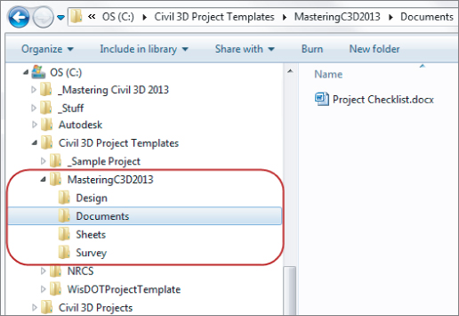
1. Open Windows Explorer and navigate to C:Civil 3D Project Templates.
2. Create a new folder titled MasteringC3D2013.
3. Inside
MasteringC32013, create subfolders called
Design, Documents, Sheets, and
Survey as shown in
Figure 18.1.
5. Place the file in the Documents folder you created in step 3.
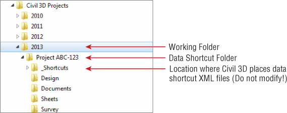
This structure will appear inside Civil 3D and in the working folder when a project is created. A Documents folder is included as an example of other, non-Civil 3D–related folders you might have in your project. The Project Checklist.doc file will also be automatically copied to each project you create from this template.
Setting a Working Folder and Data Shortcuts Folder
You can think of the working folder as a project directory. The working folder can contain a number of projects, each with a data shortcut folder where the shortcut files reside.
In this exercise, you'll set the working folder and create a new project:
1. Create a new blank drawing using the template of your choice.
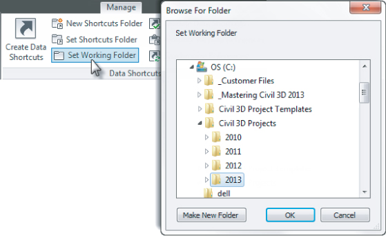
2. From the Manage tab ⇒ Data Shortcuts panel, click Set Working Folder, as shown in
Figure 18.2.
3. Browse to your local C drive ⇒ Civil 3D Projects folder.
This folder is created automatically on your local drive when Civil 3D is initially installed.
4. With the Civil 3D Projects folder highlighted, click Make New Folder, and make a new folder called 2013.
5. Highlight the new folder, and click OK.
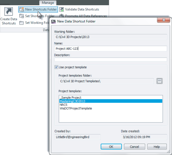
6. From the Manage tab ⇒ Data Shortcuts Panel, click New Shortcuts Folder to display the New Data Shortcut Folder dialog shown in
Figure 18.3.
7. Type
Project ABC-123 for the folder name, and toggle on the Use Project Template option, as shown in
Figure 18.3.
8. Select the MasteringC3D2013 folder from the list, and click OK to dismiss the dialog.
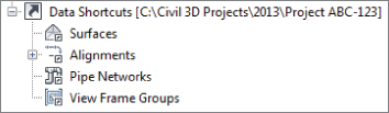
Notice that the Data Shortcuts branch in Prospector now reflects the path of the
Project ABC-123 project, as shown in
Figure 18.4.
If you open Windows Explorer and navigate to C:Civil 3D Projects2013Project ABC-123, you'll see the folder from the Mastering project template plus a special folder named _Shortcuts, as shown in Figure 18.5. Civil 3D creates this folder for you and is where the data shortcuts will live.
In real life, your working folder and data shortcut folder will probably be on a local network server. If you have an established workflow for creating project folders and do not wish to use the Civil 3D project template, you can manually create a folder named _Shortcuts. This _Shortcuts folder needs to be inside the folder set as your Data Shortcut folder in Civil 3D (i.e., one folder level down, as shown in Figure 18.5).
Creating Data Shortcuts
With a shortcut folder in place, it's time to use it. It's a best practice to keep the drawing files in the same location as your shortcut files, just to make things easier to manage. In this exercise, you'll publish data shortcuts for the alignments and layout profiles in your project:
1. Open the Points-Surface.dwg (Points-Surface_METRIC.dwg) file, which you can download from this book's web page.
This drawing contains points and an existing ground surface.
2. From the Application menu, click Save As, and save a copy of this drawing to C:Civil 3D Projects2013Project ABC-123Survey.
Location, Location, Location
When working with data shortcuts, location matters! You save the project in its permanent home. Making a data shortcut to the surface and moving the file afterward would cause a broken reference.

3. From the Manage tab ⇒ Data Shortcuts Panel, click Create Data Shortcuts.
4. Place a check mark next to Surfaces and EXISTING SURFACE, as shown in
Figure 18.6, and click OK.
5. Save and close the current drawing file.
6. Open the Alignments-Profiles.dwg (Alignments-Profiles_METRIC.dwg) file from your class data.
This file contains three alignments that you will add to the list of data shortcuts.
7. From the Application menu, click Save As, and save a copy of this file to C:Civil 3D Projects2013Project ABC-123Design.
8. From the Manage tab ⇒ Data Shortcuts panel, click Create Data Shortcuts.
9. Place a check mark next to all the alignments (as shown in
Figure 18.7), and click OK.
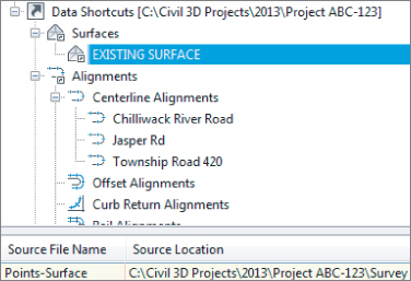
You should now have surfaces and alignments available for use in the data shortcuts listing in Prospector, as shown in Figure 18.8. Notice in Figure 18.8 how highlighting the data shortcut in the listing reveals the Source Location at the bottom of Toolspace.
Keep Alignments-Profiles.dwg (Alignments-Profiles_METRIC.dwg) open for use in the next exercise.
Creating a Data Reference
Now that you've created the shortcut files to act as pointers back to the original drawing, you'll use them in other drawings. In this section you will use and create data references. You will also use data references in conjunction with a traditional XREF to create cross-section sheets.
Shortcut references are made using the Data Shortcuts branch within Prospector. In this exercise, you'll create references to the objects you previously published to the Concord project.
You need to have completed the previous exercises to continue.
1. Keep working in Alignments-Profiles.dwg (Alignments-Profiles_METRIC.dwg).
2. In Prospector ⇒ Data Shortcuts collection, right-click EXISTING SURFACE and select Create Reference, as shown in
Figure 18.9.
3. Leave all surface options at their defaults, and click OK. Zoom extents to view the surface.
4. Save the current drawing and keep it open for the next exercise.
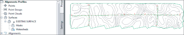
You should now see the surface in the drawing. At first glance, it does not look different from other surfaces you've worked with within Civil 3D. If you examine the Surfaces branch of Prospector, however, you'll see that the Definition category under EXISTING SURFACE is missing (as shown in Figure 18.10). This is because you cannot edit the surface data in the host drawing. If a change needs to be made to the surface, you would need to open the file where EXISTING SURFACE was originally created.
Any changes to the surface will be communicated through the data shortcut to the drawings where it is referenced.
Renaming Objects on Reference Creation
Avoid it. Not only is it confusing to people who open the file after you, it is simply bad practice. You may experience broken references if the name of an object changes during the Create Reference part of the process.
In the exercise that follows, you will use the skills you've learned in Chapter 7, “Profiles and Profile Views,” to create an existing ground profile and a design profile. After you have all the information, you will use skills from Chapter 10, “Basic Corridors,” to put the information together. You need to have completed the previous exercises to continue.
1. Keep working in Alignments-Profiles.dwg (Alignments-Profiles_METRIC.dwg).
2. Select the longest alignment in the drawing, Township Road 420.
3. In the Alignment contextual tab ⇒ Launch Pad panel, click Surface Profile, and then do the following:
A. Click Add.
B. Click Draw In Profile View.
4. Click Create Profile View, and click to place the profile view anywhere in the drawing.

5. Select the Profile view. From the Profile View contextual tab ⇒ Launch Pad, click Profile Creation Tools.
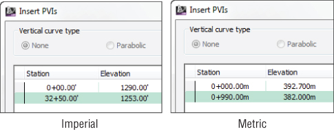
6. Name the new profile TR 420 Design.
7. Leave all other options at their defaults, and click OK.

8. From the Profile Layout Tools, click Insert PVIs Tabular.
9. Enter the data for your unit system, as shown in
Figure 18.11.
You can close the Profile Layout Tools toolbar when complete.
10. Save the drawing.
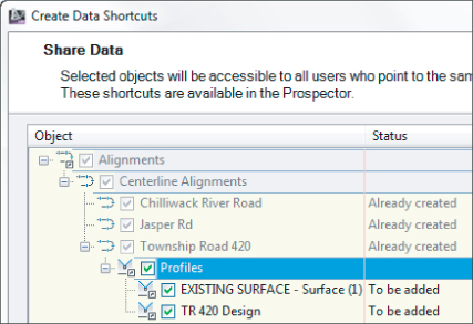
11. From the Manage tab ⇒ Data Shortcuts panel, click Create Data Shortcuts.
12. Place a check mark next to Profiles, as shown in
Figure 18.12, and click OK.
The alignments that you added earlier are listed but are grayed out. Once you add an item to the data shortcut list, you do not need to re-add them. Only new data will be added to the list of data shortcuts.
13. Save and close Alignments-Profiles.dwg (Alignments-Profiles_METRIC.dwg).
14. From your class files, open Corridor.dwg (Corridor_Metric.dwg).
15. From the Application menu, click Save As, and save the drawing to C:Civil 3D Projects2013Project ABC-123Design.
16. From the Prospector tab of Toolspace, expand the Data Shortcuts branch, and then expand Surfaces.
17. Right-click EXISTING SURFACE, and click Create Reference.
18. Leave all default settings, and click OK.
19. From the Prospector tab of the toolbar, expand Alignments ⇒ Centerline Alignments ⇒ Township Road 420 ⇒ Profiles.
20. Right-click TR 420 Design and select Create Reference, as shown in
Figure 18.13.
21. Leave all settings at their default, and click OK to the Create Profile Reference dialog.
If you zoom extents in the drawing, you should now see the alignment and existing surface. Because all profiles must be associated with an alignment, creating a reference to a profile will automatically bring the alignment along for the ride.
The profile data is referenced but is not currently visible. If you wanted to, you could create a profile view. However, we do not need the profile to be visible to create a corridor.
22. From the Home tab of the Ribbon ⇒ Create Design panel, click Corridor and do the following:
A. Name the corridor Township Road 420.
B. Verify the alignment is set to Township Road 420.
C. Verify that the profile is set to TR 420 Design.
D. Set the assembly to Typical Section.
E. Set Target Surface to EXISTING SURFACE.
F. Clear the check box for Set Baseline And Region Parameters.
G. Click OK.
23. After the corridor builds successfully, save and close the drawing as you will be coming back to it later on.

Sending Cross-Section Sheets to Their Own Drawing
Unlike plan and profile sheets, cross-section sheets do not give you any options for automatically creating layouts in new sheets.
It is a great idea to send cross sections to a drawing separate from the corridor. If you don't use data shortcuts for anything else, we implore you to use them for cross sections.
There are two main reasons for separating sections from the herd:
- You don't need to worry that the annotation scale that looks good for cross sections looks strange for other modelspace items.
- Corridor drawings already contain lots of data; send section sheets to their own drawing to keep file size down.
The following exercise builds from what you have already created in this chapter. You will step through the procedure of creating cross-section sheets using a combination of XREF and data shortcut functionality. You may wish to review Chapter 13, “Cross Sections and Mass Haul,” if you have trouble completing the steps in this exercise.
1. Start a new drawing with the Civil 3D template of your choice.
2. Save the drawing to the folder C:Civil 3D Projects2013Project ABC-123Sheets as Sections.dwg.
3. From the Prospector tab of Toolspace ⇒ Data Shortcuts ⇒ Alignments ⇒ Centerline Alignments, right-click Township Road 420 and click Create Reference.
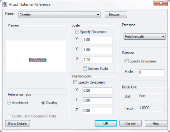
4. From the Insert tab of the Ribbon ⇒ Reference panel, click Attach.
5. At the bottom of the Select Reference File dialog, set the Files Of Type to Drawing (*.dwg).
6. Browse to C:Civil 3D Projects2013Project ABC-123Design and select Corridor.dwg (Corridor_METRIC.dwg) and click Open.
A. Set the reference type to Overlay.
B. Set the path type to Relative Path.
C. Clear the check box for Insertion Point Specify On Screen.
D. Click OK.
You will receive an Unreconciled New Layers message, which you can dismiss by clicking the X.
Zoom extents to get a look at your drawing so far. You now have everything you need to create sample lines in this new drawing.
7. From the Home tab ⇒ Profile & Section Views panel, click Sample Lines, press Enter to pick Township Road 420 from a list, and click OK.
8. In the Create Sample Line Group dialog, keep all default options and styles.
Pause here and take notice of a few peculiar things. The EXISTING SURFACE is appearing even though there is no data reference to it. Additionally, you should see the corridor listed. Data references to corridors do not exist in Civil 3D, but you can still link to the data without it. Sample lines are “strong enough” to pull this data out of an external drawing reference. If you had created corridor surfaces, those too would appear in the sample lines.
9. Click OK when you are done having your mind blown.
10. From the Sample Line Tools, click By Range Of Stations.
11. Set the left and right swath widths to 100′ (30 m).
12. Keep the default sampling increments, and click OK.
13. Press Esc to complete the command.
14. Set your annotation scale to 1≤=20′ (1:500).
15. From the Home tab ⇒ Profile And Section Views panel ⇒ Section Views, click Create Multiple Views.
16. Leave all the defaults, and click Create Section Views.
17. Click to place the sheets in the drawing.
18. Save the drawing and keep it open for the next exercise.
After you have successfully created sample lines, the procedure for creating section sheets is exactly the same as you learned in previous chapters.
Updating References
When it's necessary to make a change, you can use the tools in the Data Shortcut menu to jump back to that file, make the changes, and refresh the reference:
1. If it is not open from the exercise in the Real-World Scenario “Sending Cross-Section Sheets to Their Own Drawing,” open the file Sections.dwg.
Hopefully, you saved it to C:Civil 3D Projects2013Project ABC-123Sheets.
2. Keep this drawing open and also open the file Corrior.dwg.
3. In Prospector, expand Data Shortcuts ⇒ Surfaces.
4. Right-click EXISTING SURFACE and select Open Source Drawing, as shown in
Figure 18.14.
At this point you should have three drawings open (Corridors, Points-Surface, and Sections). You can use Ctrl+Tab on your keyboard to cycle through open drawings. You can also use the Quick View Drawings button at the bottom of the AutoCAD window to switch between open drawings.
Points-Surface.dwg (Points-Surface_METRIC.dwg) should be the active drawing and ready to make updates. Remember that the surface is read-only in all other project files; this is the only drawing where changes can be made to the surface.

5. On the Insert tab ⇒ Import panel, click Points From File.

6. In the Import Points dialog, click the plus sign and browse for NewSurfacePoints.txt (NewSurfacePoints_METRIC.txt). Select this file and click Open.
This file is part of the chapter data set, and can be downloaded from this book's web page.
7. Set Point File Format to PNEZD (Comma Delimited), leave all other settings at their defaults, and click OK.
8. In Prospector, right-click Point Groups and select Update.
9. In Prospector ⇒ Surfaces, right-click EXISTING SURFACE and select Rebuild.
10. Save and close Points-Surface.dwg (or Points-Surface_METRIC.dwg).
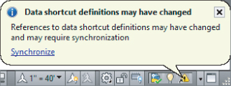
11. Switch drawings so that Corridor.dwg (Corridor_METRIC.dwg) is the active drawing.
Shortly after bringing this drawing to the forefront, you should see a bubble message appear indicating that Data Shortcut Definitions may have changed, as shown in
Figure 18.15.

12. Click the Synchronize link in the message.
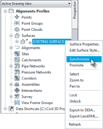
In some situations you may not see the large bubble message. You may just see a warning symbol in the reference indicator at the bottom of the screen. In that case, you can always synchronize directly from the right-click menu of the referenced object, as shown in
Figure 18.16.
You will receive a message in Panorama indicating that the item was synchronized.
13. Dismiss this message by clicking the green check box.
14. In Prospector ⇒ Corridors, right-click the Township Road 420 corridor, and select Rebuild.
15. Save and close Corridor.dwg (Alignments-Corridor.dwg).

16. Switch to Sections.dwg.
This time, you will receive a message that your XREF is out of date, as shown in
Figure 18.17. If you accidentally dismiss this message without updating, a warning symbol will remain in the tray area at the bottom of your screen. You can always right-click to reload the reference from this icon.
17. Click Reload Corridor.
Your sections should now reflect all the design changes. If you receive another message regarding unreconciled layers, click the X to dismiss it.
18. Save and close all drawings.
Best Practices for Employing Data Shortcuts
When people first add data shortcuts into their workflow, they often have the following questions:
only work on small sites by myself. Do I need to use data shortcuts?
Even if you work on very small projects, you should use data shortcuts for cross-section sheets.
How should I break up my project?
Every project is different, of course, but use this as a guideline:
Existing Survey and Surface
The first drawing you create is usually the existing conditions. Keep survey points, figures, and the existing surface together in the first drawing. Create a data shortcut to the existing surface. Points can't be shared via data shortcut, but you can always use a point query to pull specific points between drawings.
Alignments and Profiles
While the existing surface is being fine-tuned, you can get to work on developing the alignments and profiles right away. Alignments and profiles are fairly lightweight in terms of how much data they consume. You can usually store all of your project's alignment and profile data in the same DWG.
Corridors
When in doubt, use multiple corridor drawings. This way several designers can be working on different segments of the project at once. Be mindful not to put too much data in one file—you may want to keep interchanges and roundabouts in their own drawings. At the end of the process, data shortcuts will allow you to bring proposed surface data back together.
Pipe Networks and Pressure Networks
Pipe networks can be used with data shortcuts, but currently pressure networks cannot. Keep this in mind when splitting up your projects.
Site Grading
Parking lots, building pads, and other site items are good candidates for data shortcuts.
Where is the data stored?
The data for a data shortcut is stored in the source DWG file. The data shortcut file itself is simply a pointer that keeps track of filenames and paths. No object data is stored with the data shortcut.
Can I store my working folder and data shortcut folder on a network?
Yes! This is an excellent way to work. You will want to keep your working folder, data shortcut folder, and project drawings on a local network drive, however (i.e., within your building).
What if I need to share the project data with another office?
This question is where data shortcuts get a little tricky. How to handle multiple offices depends on the scenario:
Example 1
Your Houston office is working on the road design while the Chicago office is working on grading. You want a live, remote workflow with frequent syncing between offices. For this type of scenario, you would be better served by Autodesk® Vault Collaboration:
Example 2
Your Houston office has completed this stage of the road design and the next phase will be done in the Chicago office. In other words, no live data exchange needs to take place. You can use eTransmit (discussed later in this chapter), or you can move the entirety of the project's Data Shortcut folder to the new location.
Fixing Broken References
A broken reference is fairly easy to fix, but you will not be able to continue working in your design until broken references are rectified.
Actions that will cause broken references include:
- Renaming a source file
- Moving a source file
- Missing a source file
- Renaming project folders
In the following exercise you will connect to an existing project and fix the broken data references that you find. You do not need to have completed the previous exercises to continue.
1. Using Windows Explorer, locate the folder called Project XYZ-789.
This is part of the download for this chapter at the book's web page.
2. Copy this folder and its contents to C:Civil 3D Projects2013.
3. Open the file XYZ-789 Corridor.dwg, located in C:Civil 3D Projects2013Project XYZ-789Design.
This file contains a number of references pointing to a file that was renamed. Panorama will appear with the messages regarding the problems that it found.
4. Close the Panorama window by clicking the green check mark.
In Prospector ⇒ Alignments ⇒ Centerline Alignments you will see that all three alignments have a warning chevron next to them.
5. Right-click Donner Pass and select Repair Broken References, as shown in
Figure 18.18.
6. Navigate to the XYZ-789 Alignment.dwg file in the …Project XYZ-789Design folder, and click Open.
After fixing the first broken reference, Civil 3D determines whether this drawing can be used to fix other reference issues. If it finds more fixes, you will see the message shown in
Figure 18.19.
7. Click Repair All Broken References.
Civil 3D will match the Civil 3D objects with broken references to objects in the selected drawing.
The ability to repair broken links helps make file management a bit easier, but there will be times when you need to completely change the path of a shortcut to point to a new file. To do so, you must use the Data Shortcuts Editor.
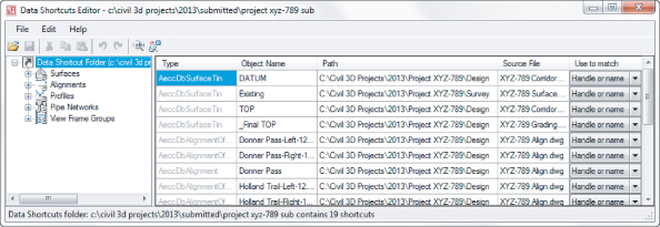
The Data Shortcuts Editor
Civil 3D tenaciously tries to hang on to links to the information it uses. The Data Shortcuts Editor is used to update or change the file to which a shortcut points. You may want to do this when an alternative design file is approved, or when you move from preliminary to final design.
In the following exercise, you'll move the example project and ensure that the data shortcuts are updated (the procedure is the same for both metric and Imperial units):
1. Save and close any drawings you have open and close Civil 3D.
2. Using Windows Explorer, browse to C:Civil 3D Projects2013.
3. Inside the 2013 folder, create a new folder called Submitted.
4. In the download for this chapter is a folder called Project XYZ-789. Copy Project XYZ-789 to the Submitted folder. Rename the folder Project XYZ-789 to Project XYZ-789 SUB.
Your resulting folder structure should look like
Figure 18.20.
You are keeping the original intact for archive purposes. If you attempted to open drawings that reference data in the new location, you would see that the data references are looking at the original path.
Next, you will ensure that Civil 3D will use the new path in the Submitted version.

5. In Windows, choose Start ⇒ All Programs ⇒ Autodesk ⇒ Autodesk Civil 3D 2013, and click the Data Shortcuts Editor to load it.
6. Select File ⇒ Open Data Shortcuts Folder to display the Browse For Folder dialog.
7. Navigate to C:Civil 3D Projects2013SubmittedProject XYZ-789 SUB, and with the Project XYZ-789 SUB folder highlighted, click OK.
There are several things that need to be changed before the new phase of the project can begin. Some of the data references are looking for the incorrect file.
Notice that the Path column of the table still refers to the old path. In order to make a clean break from the old project to move forward into the Submitted version, you need to change all these.

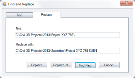
8. Choose Edit ⇒ Find And Replace.
Unfortunately, there is no browse option here but you can use the basic Windows Copy and Paste tools to make this a little easier. You can also click your cursor in one of the fields you wish to change for a starting point.
9. Type
C:Civil 3D Project2013Project XYZ-789 in the Find field, and
C:Civil 3D Projects2013SubmittedProject XYZ-789 SUB in the Replace With field, as shown in
Figure 18.22.
10. Click Replace All.
Your data shortcut paths and source files are now correct (as shown in
Figure 18.23) and ready for more action.
11. Highlight the Alignments branch on the left side of the Data Shortcuts Editor.
This will narrow the focus to alignment information.
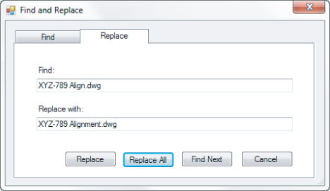
12. Choose Edit ⇒ Find And Replace.
13. In the Find field, enter XYZ-789 Align.dwg.
14. In the Replace field, enter
XYZ-789 Alignment.dwg, as shown in
Figure 18.24.
15. Click Replace All.
All of the source file paths for alignments should be updated.
16. You can now close the Data Shortcuts Editor and return to Civil 3D.
eTransmit + Data Shortcuts = Awesomesauce!
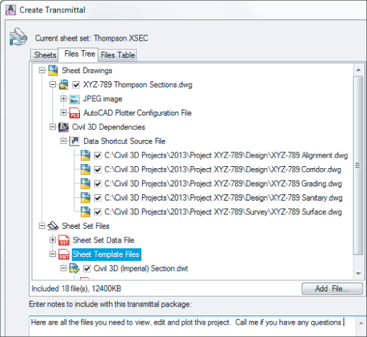
If you need to pass a project on to another designer with all the information they need, use the eTransmit command. If a file contains a data shortcut, the eTransmit command will recognize the link and include the necessary drawings. You can even include non-AutoCAD files such as Word or Excel documents by clicking the Add File button.
AutoCAD will generate a zip file that contains any XREF files (including DWF, DGN, PDF, or TIF references), plot configurations, images, and templates used in sheet creation. When your recipient unzips the file, the connections between drawings are maintained.
eTransmit is the best way to send Civil 3D files with the assurance that you are not sending a pile of broken references.
Sharing with Earlier Versions of Civil 3D
As crazy as it sounds, not everybody is using Civil 3D 2013, so you need to know how to work with the “world outside.”
Civil 3D is not backward compatible. While the Save As command works fine for base AutoCAD objects (such as lines, arcs, and circles), the intelligence behind Civil 3D objects is inaccessible to previous versions of both Civil 3D and AutoCAD.
Contrary to what many people claim, this is not an evil conspiracy. Civil 3D objects evolve year to year. As functionality changes, objects get leaner and smarter. Under the proverbial hood, the underlying components of things like surfaces, alignments, and corridors are too different from those of previous years to work in older versions.
If possible, avoid the need to “go backward.” Be mindful that the moment you save a previous version drawing in a newer version of Civil 3D, it will no longer work properly in the old version of Civil 3D.
Alas, the need to send data to older versions of Civil 3D is not always avoidable. In the following exercise, you will step through an example of what needs to happen to force Civil 3D to previous versions:
1. Open LandXML-OUT.dwg (LandXML-OUT_METRIC.dwg), which can be found at this book's web page.

2. From the Output tab ⇒ Export panel, select Export To LandXML.
3. Click OK.
4. In the Export LandXML dialog, browse to the same folder as the source drawing.
5. Keep the default name (the dialog will pick up the name of the drawing you are exporting from), and click Save.
You now have as much Civil 3D as possible packed up into the LandXML file. This file contains:
- Alignments
- Point groups and points
- Surfaces
- Profiles
- Pipe data
The next few steps will break the Civil 3D objects down into base AutoCAD components and save them to a previous version format.

6. From the Application menu ⇒ Export ⇒ DWG, select 2010.
7. In the Export Drawing Name dialog, browse to the same folder as the source drawing.
8. Keep the default name (the dialog will pick up the name of the drawing you are exporting and add an ACAD- prefix), and click Save.
The resulting file is a “dumbed-down” version of your original Civil 3D file.
Next you will go through the process of reassembling the data as if you were working on a previous version of Civil 3D.
9. Start a new drawing based on the template of your choice.
10. Save the file as LandXML-IN.dwg in the location of your choice.
You need to start with a Civil 3D template, because exporting to earlier versions will destroy Civil 3D–specific styles and settings.

11. On the Insert tab ⇒ Block panel, click Insert.
12. In the Insert dialog, clear the Insertion Point, Scale, and Rotation check boxes.
13. Place a check mark next to Explode.
14. Click Browse and locate the file ACAD-LandXML-OUT.dwg or ACAD-LandXML-OUT_METRIC.dwg that you created in steps 7 and 8 and click Save.
15. Click OK.
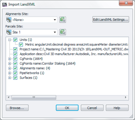
16. On the Insert tab ⇒ Import panel, click LandXML.
17. In the Import LandXML dialog, browse for the XML file you created in steps 4 and 5, and click Open.
18. Click OK.
You may receive several messages in Panorama because of the Parts List differences between the source file and this new file.
19. Dismiss Panorama, and save and close the drawing.
What Is LandXML?
LandXML is not specific to Civil 3D. It is a consortium of fellow Civil 3D users wanting to standardize a way of sharing files in a nonproprietary format.
In the Import LandXML dialog was a drop-down list that let you select the version of LandXML. This is a result of that consortium. The latest as of this writing is the 1.2 schema. Most CAD programs have methods of importing and exporting LandXML files, and this is one way to tackle that barrier.
Map Tools: A Transformative Experience
A common occurrence in Civil 3D is needing to show an aerial image as it relates to your design. The coordinate system of the photo is not always in the same units or coordinate system as your drawing.
Standard image attachment tools will not automatically transform the image. Even if both your drawing and the image are assigned coordinate systems, Civil 3D will not presume to move one into the other. You need to use the Map portion of Civil 3D to force the coordinate transformation.
Here are the general steps you will need to follow in order to transform an image from its original coordinate system to the coordinate system of your Civil 3D drawing:
1. Start a new drawing and set it to the same coordinate system as the image.
This will be referred to as the source coordinate system.
2. Get to the Map workspace.
3. Insert the image to the new, empty drawing using the MAPIINSERT command.
4. Save and close the initial drawing.
5. Open your project drawing and ensure that it is set to the correct coordinate system.
This will be referred to as the destination coordinate system in this section.
6. Use the Map 3D Attach command to attach the source drawing.
7. Use the ADEQUERY command to pull the image across to the destination coordinate system.
In the following sections, you will work through these steps in greater detail.
Finding Your Map Tools
Autodesk® Map 3D is a product that bridges the gap between GIS and CAD. Because infrastructure designers often dip their toes in the GIS waters, Civil 3D contains all the tools that come with Map 3D. To access the tools you will work with, you will need to change your active workspace.
In the following exercise, you will change workspaces.
1. Start a new drawing based on the _Autocad Civil 3D (Metric) NCS.dwt.
Even if your preferred working units are feet, the first step in the process will be working with the TIFF image in its native coordinate system. The TIFF you will be working with was obtained from the United States Geological Survey (USGS) website (
http://viewer.nationalmap.gov/viewer/). Like most of the data from USGS, the file is in UTM NAD83 and is in metric units.
2. Save the file in your example file folder as SOURCE.dwg.
3. From the Settings tab of Toolspace, right-click on the name of the drawing, and select Edit Drawing Settings.
4. On the Units And Zone tab, enter UTM83-16 in the Selected Coordinate System Code field.
This will set the drawing's coordinate system to UTM83 Zone 16, Meter.
5. Click OK to dismiss the Edit Drawing Settings dialog.
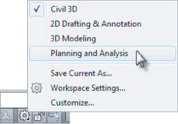
6. Click the Workspaces icon in the lower-right corner of the screen and select Planning And Analysis, as shown in
Figure 18.27.
7. Save the drawing and keep it open for the next exercise.
Inserting the Image
Now that you have your source drawing set, it is time to insert the file. In this example you'll use a TIFF, but the process is the same regardless of the type of image file you are working with.
1. Continue working in the file SOURCE.dwg that you created in the previous exercise. Remain in the Planning And Analysis workspace.

2. From the Home tab ⇒ Data panel, click the MAPIINSERT button.
3. In the Insert Image dialog, set Files Of Type to Tagged Image File Format (TIFF).
4. Browse to the files you downloaded for this chapter, select MKE94-43-41.tif, and click Open.
5. In the Image Correlation dialog, click OK.
The insertion point and units are coming from the TFW file that accompanies the image. The two files have the same name but different file extensions.
6. Zoom extents to see the image in your file.
7. Remain in the Planning And Analysis workspace, and save and close SOURCE.dwg.
If you happen to receive a TIFF that is in the same coordinate system as the rest of your project, you could use the MAPIINSERT command directly in the project. A coordinate system match may happen periodically, but more often than not you will need to continue the process as outlined in the next section.
Transforming to Local Coordinates
The first thing you should do in any project drawing is set your coordinate system, as seen in Figure 18.28. Be sure you have a coordinate system set before you import your survey and create Civil 3D data. Changing coordinate systems or units partway through a project will not adjust any existing information and is generally a bad idea.
The technique outlined in this section works on images and any base AutoCAD object. If you have AutoCAD objects (lines, arc, circles, etc.) in a file that has a coordinate system assigned to it, you can attach the file and query-in data to do an exact transformation.
Locate Using Geographic Data
For XREFs and block insertion, you will see an option called Locate Using Geographic Data.
Be wary of this option for Civil 3D and Map applications. It is intended for base AutoCAD users who simply want to line up drawings; it does not perform a true coordinate transformation.
1. Open the drawing Destination.dwg (Destination_METRIC.dwg), which you can download from this book's web page.
These files have been set to a Wisconsin State Plane coordinate system.

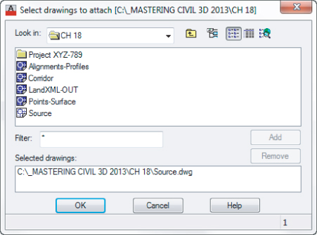
2. In the Planning And Analysis workspace, select the Home tab ⇒ Data panel, and click Attach.
3. Use the Select Drawings To Attach dialog to browse to your file.
4. Highlight SOURCE.dwg, and click Add. Click OK.
The file will appear at the bottom of the dialog in the Selected Drawings section, as shown in
Figure 18.29.

If you are using a drive other than the C drive of your computer to store the files for this process, you will need to click the Create/Edit Aliases button to access additional drives.

5. From the Home tab ⇒ Data panel, click Define Query.
6. Click the Location button.
7. Set the boundary type to All, and click OK.
8. Set the query mode to Draw. Leave all other options at their defaults.
9. When your dialog resembles
Figure 18.30, click Execute Query.
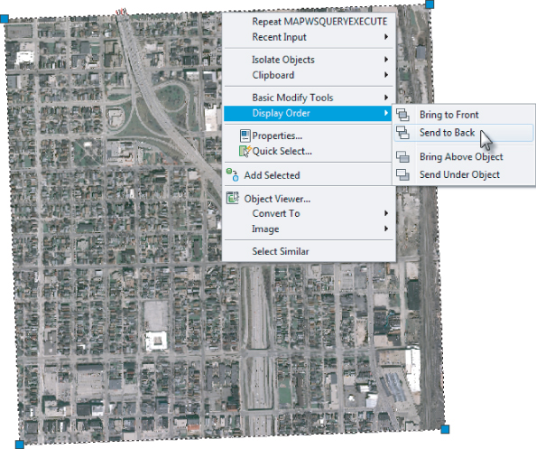
You should now see the image translated to the correct coordinate system.
10. Select the image, right-click, and select Display Order ⇒ Send To Back, as shown in
Figure 18.31.
11. Save the drawing.
12. Because you have used Map 3D functionality to attach drawings, you will see a message about maintaining the association between drawings. Click OK to dismiss this warning.
An Alternate Method
To insert and transform a georeferenced image into Civil 3D, you could also use the Map Data Connect tool from the Planning And Analysis workspace in the Home ⇒ Data panel (or type MAPCONNECT). This method works for various data types, including raster images as shown here.
The advantage of this method is that it involves fewer steps.
There are several reasons we made you do it the “hard way”:
- If an image is inserted via the attach and query method, as you did in the previous exercise, the image can be manipulated in all the same ways as an image attached via base AutoCAD—that is, you can crop it, make it transparent, and adjust it.
- Images brought in through the MAPCONNECT command can be color adjusted, but that's it.
- If you use the attach and query method, you can transform anything—images and entire CAD files, if necessary.
The Bottom Line
Create a data shortcut folder.
The ability to load design information into a project environment is an important part of creating an efficient team. The main design elements of the project are available to the data shortcut mechanism via the working folder and data shortcut folder.
Master It
Using the drawing MasterWorkflow.dwg (MasterWorkflow_METRIC.dwg), create a new data shortcut folder called Master Data Shortcuts. Use the _Sample Project project template.
Create data shortcuts.
To allow sharing of the data, shortcuts must be made before the information can be used in other drawings.
Master It
Save the drawing to the Source Drawings folder in the project you created in the previous exercise. Create data shortcuts to all the available data in the file MasterWorkflow.dwg (MasterWorkflow_METRIC.dwg).
Export to earlier releases of AutoCAD.
Being able to export to earlier base AutoCAD versions is sometimes necessary.
Master It
Using MasterWorkflow.dwg (MasterWorkflow_METRIC.dwg), export the Civil 3D file so it can be used by a user working in base AutoCAD 2010.
Export to LandXML.
Being able to work with outside clients or even other departments within your firm who do not have Civil3D is an important part of collaboration.
Master It
Using MasterWorkflow.dwg (MasterWorkflow_METRIC.dwg), create a LandXML file will all of the exportable information.
Transform coordinates between drawings.
Most project locations have the ability to use several coordinate systems or units. Being able to correctly manipulate a drawing's coordinate system is extremely important.
Master It
The file TransformThis.dwg is in Universal Transverse Mercator (UTM) North American Datum (NAD) 83, Zone 10, in meters. Start a new drawing based on _Autocad Civil 3D (Imperial) NCS.dwt or _Autocad Civil 3D (Metric) NCS.dwt. Set the new drawing's coordinates to AND 83 California State Plane Zone 3 (US Foot or Meters, depending on which template you used).